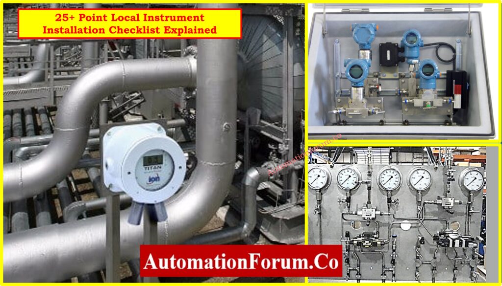
In industries including oil and gas, power plants, chemicals, and water treatment, proper installation of local field instruments is an important step in making sure that processes are accurate, safe, and meet engineering standards. Every local instrument, from pressure gauges and thermowells to transmitters and switches, helps with accurate monitoring and control.
The following section has a complete installation checklist with explanations for each step to make sure that project engineers, site supervisors, and QA/QC inspectors do things the right way. At the end, we also give a checklist in Excel that you may download.
Why use a Local Instrument Installation Checklist?
- Makes sure that the installation meets ISA, IEC, or project-specific standards.
- Reduces the need for rework and safety risks
- Helps keep data safe and the control logic working.
- Makes the commissioning and handover processes go faster
Now, we will look at the most important things on a standard installation checklist.
25+ Point Local Instrument Installation Checklist Explained
All of the following checks assist make sure that the installation is done correctly and that it will work well for a long time.
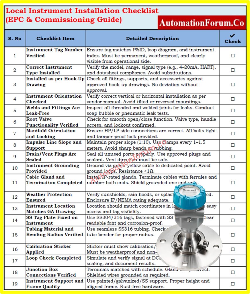
1. Instrument Tag Number Verified
- Make that the tag matches the P&ID, loop diagram, and instrument index.
- Tag should be permanently etched or laser-marked, not only with a sticker.
- The tag plate must be able to withstand rain and rust.
- It needs to be easy to see from the operational side.
Clear tagging makes testing, loop checking, and future maintenance easier. The tag should be easy to see, able to withstand the weather, and match the control logic. Tag ID errors might cause data to not match up or controls to not work.
2. Correct Instrument Type Installed
- Compare the installed device to the approved vendor datasheet.
- Make that the range, signal type (such 4-20mA or HART), and accuracy are all correct.
- Do not replace with lookalike instruments without MTO approval.
Even if the model is the same size or does the same thing, it could have a different range, output, or electrical classification. Before giving the go-ahead for installation, always check the nameplate against the approved documents.
Refer the below link for the How to Safely Check the mA Current of an Instrument Loop Using a Multimeter
3. Installed as per Hook-Up Drawing
- The mounting parts (valves, fittings, brackets) must fit the hook-up.
- Follow the rules for elevation and the tubing parameters.
- Don’t take shortcuts while fixing brackets or clamping supports.
- Any changes to the drawing must be written down and approved.
Hook-up drawings show how to arrange tubing, valve manifolds, brackets, supports, and seals. If you don’t follow these rules, you could get signal problems, have trouble getting to things or have your machine break down when it gets too much stress.
Refer the below link for the lear more about Instrument Hook-up Diagrams
4. Instrument Orientation Checked
- Check the installation position (vertical/horizontal) that the manufacturer says to use.
- Don’t mount it upside down because it will impact calibration and sensing.
- Mounting that is slanted or twisted changes readings and makes it harder to get to service.
- Orientation should also help with safe draining and venting.
Wrong orientation changes measurements that are sensitive to gravity and how quickly sensors respond. If pressure and level transducers are installed upside down or at an angle, they may drift or give incorrect readings.
5. Welds and Fittings are Leak-Free
- Look closely at all welded and threaded joints to see if there are any cracks or slag.
- Do soap bubble or pneumatic leak tests to check for tightness.
- Put the right sealant (PTFE or anaerobic compound) on the threads.
- You shouldn’t use oil or grease on tools that are utilized for oxygen or clean service.
Leaks can cause explosions, health problems, and problems with the process. Over time, even tiny leaks in impulse lines or fittings can change measurements or break transmitters because they lose pressure.
Approved Method Statement for Pressure Test and Leak Test of Instrument Tubing: Method Statement for Pressure Test and leak Test for Instrument Tubing and Impulse line
6. Root Valve Functionality Verified
- Make that the right type (ball or needle) is installed according to the specs.
- The valve handle should be easy to reach and have clear markings.
- Check the function: open and close smoothly without leaking.
- If you can’t get to the region, use a longer handle or lockout.
These valves keep the process separate while maintenance or calibration is going on. If a valve is jammed, turned the wrong way, or broken, it might make it unsafe to isolate, which could put workers or sensors in risk.
7. Manifold Orientation and Locking
- According to the datasheet, you can install the manifold either horizontally or vertically.
- Make that the HP and LP sides are linked to the right process lines.
- There shouldn’t be any loose fittings or misalignment; all bolts must be tight.
- Locking arrangement must be tamper-proof.
If the manifold isn’t lined up correctly, it can mix up the high and low pressure sides, which can change flow or level readings. Secure locking keeps others from messing with it or shutting it off by mistake.
8. Impulse Line Slope and Support
- Keep the slope at 1:10 for liquid and 1:10 for gas/steam.
- Every 1 to 1.5 meters, there should be clamps on the support lines.
- Don’t make sharp turns or rub against things.
- Make that the tubing material (SS316) and wall thickness are standard.
Sloping (usually 1:10) makes sure that gas and steam can drain themselves and that liquids don’t get stuck in air pockets. If the tubing isn’t supported, it can shake, crack, or move, which can change the pressure reading.
Refer the below link for the Best Practices for Installing and Supporting Impulse Tubing in the Field:
9. Drain/Vent Plugs are Sealed
- Use stainless steel or brass plugs to cover ports that aren’t being used.
- Put sealant on the threads to stop them from leaking.
- Mark the status of the vent as “vented” or “plugged” for future reference.
- Make sure the vent is pointing in a safe direction and away from people.
Loose or missing plugs might cause leaks, signal drift, or safety problems. If you need to, use PTFE or anaerobic sealants, especially for applications with high pressure.
10. Instrument Grounding Provided
- Connect the ground to a special earthing strip or mesh.
- Use a green-yellow cable to ground the device.
- Don’t make ground loops; there should only be one grounding point per loop.
- Resistance must be less than a certain amount (typically less than 1 ohm).
In places with a lot of noise, floating instruments pick up electrical interference, which makes the signals unreliable. Grounding keeps sensors from getting damaged and keeps people safe in places where there are explosions.
11. Cable Gland and Termination Completed
- Use glands that are IP-rated for the zone, like IP65 or Ex-d.
- Ferrules should be used to crimp cables, and they should be tightened correctly.
- Make sure that insulated cables are only grounded at one end.
IP-rated glands keep the enclosure intact, keep moisture out, and make sure it meets flameproof or weatherproof specifications. As per grounding norms, cable screens must be terminated.
12. Weather Protection Ensured
- Use splash coverings, rain hoods, or sunshields when you can.
- Make sure that the enclosures are correctly sealed and not broken.
- Make sure that the waterproof glands are tightly fastened.
- The protection rating must be right for the area (for example, marine or desert).
In places that are outside or need to be washed down, enclosures must have an IP66 or NEMA 4X designation. To keep UV rays and moisture from damaging the surface, you should put up sunshields or rain hoods.
13. Instrument Location Matches GA Drawing
- The physical location should match the X-Y-Z coordinates in the layout drawing.
- Avoid hitting structures, pipes, or platforms.
- Height must make it easy to read and get to for servicing.
- The location ID should be the same as the tag in GA and the index.
Correct height and distance make ensuring that readings are accurate and easy to get there. Deviations could cause incorrect level compensation or make it hard to go to maintenance.
Click here to Explore more about: Cabinet Layout – GA/IA Drawing
14. SS Tag Plate Fixed on Instrument
- Tag should be stainless steel (SS304 or SS316).
- Fasten with SS wire, rivets, or clamps (no plastic cable ties).
- Font must be readable (at least 6 mm height recommended).
- Tag should withstand UV, corrosion, and cleaning pressure.
15. Tubing Material and Bending Radius Verified
- For impulse lines, use seamless tubing made of SS316.
- The minimum bending radius must meet ASME/ASTM specifications.
- To avoid kinks, use tube benders instead of your hands.
- Make that the wall thickness and outside diameter (OD) are compatible with the fittings.
Sharp curves might stop the flow or cause cracks. The right radius keeps the signal strong and eliminates pressure loss or tubing failure when the pressure is high.
16. Calibration Sticker Applied
- Label must show calibration date, due date, and technician ID.
- For outdoor instruments, use stickers that are waterproof and resistant to UV rays.
- It is important to keep a record of the calibration certificate in QA/QC paperwork.
- The sticker must not cover the dial, label, or nameplate.
It shows that the instrument was set up and ready to be put into service. It also allows maintenance staff make plans for when to recalibrate without having to turn off the machine.
Download 60+ Instrument Calibration Procedures for Pressure, Temperature, Flow & Level: Free Instruments Calibration Procedures: 60+ Step-by-Step Methods for Pressure, Temperature, Flow & Level
17. Loop Check Completed
- Simulate a signal and check the end-to-end response at the DCS/PLC.
- Check the polarity, scaling, and I/O mapping of the signal.
- Fix any wiring problems or wrong routing.
- Write down the results of the loop check in a signed-off way..
Every 4–20 mA signal or digital input/output needs to get to the right DCS/PLC channel. You need to fix signal inversion, cross-termination, or scaling issues.
Refer the below link for How to simulate 4-20ma signal with Loop Calibrator ?
18. Junction Box Connections Verified
- Cable should go through the right gland and terminal number.
- Make sure the ends are secure and there are no exposed threads.
- Terminals should have labels and match the JB timetable.
- As a rule, the shield drain wire must be either isolated or grounded.
Check the numbering of the cores, the tightness of the terminals, and the labels. When the plant is running, wrong terminals can cause signal loss, data mismatch, or control failure.
19. Instrument Support and Frame Quality
- Use supports that are painted, galvanized, or made of stainless steel, depending on the specs.
- The frame needs to be straight, in line, and able to handle vibrations.
- The height of the support should make it easy to maintain.
- Make sure that all bolts and U-clamps are rust-free and tight.
Failure might happen if supports are unstable or rusted and cause vibrations. Frames must be able to withstand wind and earthquakes and fit in with the environment (indoors or outdoors).
20. Environmental Compatibility Verified
- Check if the device is certified (Ex-d, Ex-ia) for dangerous areas.
- The material used to build must be able to handle corrosive or maritime environments.
- Check the sensor’s ambient limitations for very high or low temperatures.
- Instruments that don’t meet standards must be taken out or marked.
Devices that are inherently safe or flameproof certified are needed in dangerous locations (Zone 1 and Zone 2). Putting standard-rated tools in Ex zones can break safety rules.
21. Process Line Cleaning Verified
- Check that the line has been flushed to get rid of weld slag and other junk.
- Do a blow-through test before putting in the sensor.
- To avoid exposure, plug up any unused taps.
- Dirty lines can block impulse ports or hurt diaphragms.
Debris, welding slag, or rust can get into instruments and block their inlets, harm their diaphragms, or make readings stick. Installing after flushing protects the sensor.
22. Accessibility for Maintenance
- Make sure the technician can get to the area without any obstacles or scaffolding.
- You shouldn’t have to bend or reach too much to get to the instruments.
- Give them a platform, ladder, or railing if they need it.
- Accessibility should make it easy to repair parts and calibrate them regularly.
Difficult-to-reach devices slow maintenance, increase risk, or cause unplanned downtime. Location should allow tools and technician movement.
Field-Proven Maintenance Checklist for Pressure and Temperature Instruments: Maintenance Checklist
23. Instrument Zero Checked After Installation
- Perform zero check after tubing fill and mounting.
- Adjust transmitter zero or offset as needed.
- Document the adjusted zero for future reference.
- Ensure no trapped air or liquid is affecting zero value.
If you adjust the height of the mount or the amount of tubing, the reference point can move. For effective process measurement and alarms, this needs to be reset to zero.
Step-by-Step Method Statement for Loop Checking of Pressure Transmitter Loops: Method Statement for Loop Checking of Pressure Transmitter Loop
24. Conformance with Project Specification
- Check against the approved ITP, vendor datasheet, and drawings.
- Match the body material, gland type, and fitting threads (NPT/BSP).
- Inspection reports must include any instances of non-compliance.
- If necessary, make sure the inspection witness is there.
Using the wrong sorts of thread, materials, or fitting sizes goes against the terms of the contract. NCRs or deviation approvals must be used to record deviations.
25. Photographic Documentation
- Take pictures of the instrument from far away and up close.
- Add the tag number, support, and end date to the photo.
- Put pictures in the QA handover or project DMS.
- Use the same format for all of your names (Tag_Location_View.jpg).
Essential Pressure Transmitter Commissioning Checklist Every Engineer Must Follow: Pressure Transmitter Commissioning Checklist
Download the Excel-Based Local Instrument Installation Checklist
We’ve designed a clean, simple checklist that goes along with the 25 criteria above. You can use all of the above elements to construct a field-ready checklist in Excel for QA, FAT/SAT, or final commissioning checks.
You can print it off, utilize it in the field, or add it to your QA documentation system.
Frequently Asked Questions (FAQ) on Local Instrument Installation Checklist
1. What is a Local Instrument Installation Checklist?
A checklist that is used on the job site during construction or commissioning to make sure that pressure, flow, and temperature sensors are installed, grounded, tagged, and documented correctly.
2. Why is it important to verify impulse line slope?
Correct slope keeps gas lines and liquid lines from getting fluid traps or air pockets, which makes sure that pressure readings are correct. For proper drainage or venting, slopes of 1:10 are normal.
3. What standards should this checklist comply with?
ISA (such ISA 5.1), IEC 61511, API RP 551, ITPs that are particular to the project, and vendor submissions..
4. Is photographic documentation mandatory?
5. What is checked during a loop test?
Signal simulation from the instrument to the DCS/PLC to make sure that the scaling, wiring, polarity, and channel mapping are all right.
Test Your Knowledge on Instrument Logic Diagram
Refer the below link for Test Your Knowledge: Instrument Logic Diagram Quiz Based on Real DCS to MCC Logic Diagram