Cabinet layout describes how the components within and outside of any control or electrical panel are organized.
Cabinet layout is used to plan how the parts inside of any control or electrical panel are set up.
Refer Marshalling cabinet drawing and its significance content for more information
What is the purpose of Cabinet Layout – GA/IA drawing?
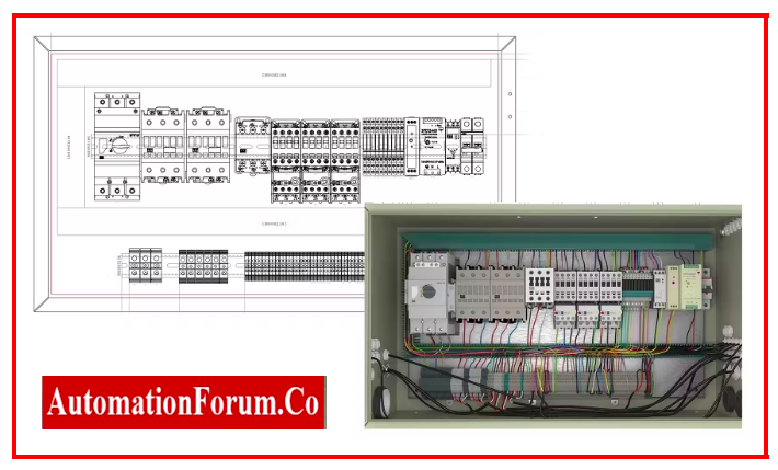
A Cabinet Layout – GA/IA drawing is a technical drawing that provides a visual representation of the layout of a cabinet or enclosure used for housing equipment, such as electrical or electronic components. The purpose of this drawing is to show the arrangement of the equipment within the cabinet, as well as its dimensions, and any relevant details such as cable entries or mounting points.
The GA (General Arrangement) drawing shows the cabinet in its entirety, depicting the overall layout of the equipment and its placement within the cabinet. This drawing is typically used to provide a general overview of the design and layout of the cabinet.
The IA (Internal Arrangement) drawing shows a detailed view of the internal components of the cabinet, including the equipment, cable routing, and any other internal details. This drawing is useful for designing and planning the installation of equipment and for ensuring that all components fit within the enclosure.
Overall, the Cabinet Layout – GA/IA drawing is an essential tool in the design and installation of equipment enclosures, providing a detailed and accurate representation of the cabinet’s layout and internal components, ensuring that the equipment is properly installed and functions correctly.
What are the documents required to prepare Cabinet Layout – GA/IA drawing?
The documents required to prepare a Cabinet Layout – GA/IA drawing may vary depending on the specific project requirements, but some of the common documents include:
- Equipment List: This document provides a list of all the equipment that will be housed in the cabinet. It should include information such as the manufacturer, model number, and dimensions of each piece of equipment.
- Floor Plan: A floor plan is a top-down view of the space where the cabinet will be located. It shows the overall layout of the room or area, including the location of doors, windows, and other fixtures.
- Electrical and Mechanical Drawings: These drawings provide details on the electrical and mechanical requirements for the equipment to be housed in the cabinet. This includes information on power and data cabling, as well as any ventilation or cooling systems required.
- Cabinet Specifications: The cabinet specifications outline the specific details of the cabinet design, such as its dimensions, construction materials, and any other special features required.
- Standards and Regulations: Any applicable standards and regulations, such as safety codes, must also be considered when preparing the Cabinet Layout – GA/IA drawing.
- By reviewing and considering all of these documents, the designer can create an accurate and detailed Cabinet Layout – GA/IA drawing that meets the specific requirements of the project.