- What is Displacer Level Sensor?
- What is level troll calibration?
- Purpose and Scope:
- Tools required for Calibration:
- Safety
- Calibration Setup
- Calibration procedure
- What is wet calibration?
- Recording calibration
- Completion of calibration
- Sample level troll Calibration Report
- FAQ on Displacer Type Level Transmitter Calibration
What is Displacer Level Sensor?

- Displacer level sensors employ the Archimedes’ Principle to determine the level of a liquid by continually weighing a displacer rod that is submerged in the process liquid.
- The displacer can be modified longer or shorter as needed and has a cylindrical shape with a constant cross-sectional area. From 14 to 120 inches are considered standard heights.
- The displacer rod feels a stronger buoyant force as the liquid level rises, appearing lighter to the sensing device, which reads the weight loss as an increase in level and sends a corresponding output signal.
- The buoyant force on the displacer rod diminishes as the liquid level drops, causing a corresponding weight rise and a corresponding signal output from the level sensor, which interprets this as a falling level.
What is level troll calibration?
Purpose and Scope:
This procedure includes calibration instructions for level transmitters and controllers of the displacer type that have been calibrated with process liquid in the procedure area.
Tools required for Calibration:
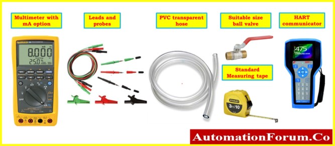
- Necessary hand tools.
- Multimeter.
- HART or handheld configurable communicator if electronic smart transmitter.
- Test leads and probes.
- Suitable ball valve with male sockets
- Transparent hose.
- Soft Cloth for cleaning.
Safety
- For specifics on fundamental safety, general recommendations, and calibrating operations in process industries, please click the link provided below.
Basic Safety & General Considerations for Process Industries Calibration Process
- Notify the DCS or the panel operator to place the level controller loop into manual mode and employ the MOS (Maintenance Override Switch) for the ESD loop.
- Locate the transmitter of the Level Displacer Type that you want to calibrate. Check to verify sure it’s the right level transmitter, and note any specific information Tag number (e.g., the manufacturer, model number, pressure range, etc.).
- Please do not turn off the power source for the level transmitter. Verify that the power supply is available at the source from any nearby junction boxes or marshalling panels close to the control room.
- Depending on the type of system, you might need to depressurize the level troll chamber and the system before calibrating the level transmitter. Use the right procedures to depressurize the system (e.g., vent the pressure by drain valve or isolate the process valves of the chamber).
- Keep in mind that this general technique may need to be modified depending on the specific equipment and process region. Always follow any manufacturer instructions and local safety regulations when working with level troll or other process equipment.
- Follow all relevant lockout/tagout procedures to prevent an unintended start. Don’t forget to keep the level troll separate from the process.
Calibration Setup
- The process area where the calibration equipment is located must be free of electromagnetic interference and vibrations. Also, the area needs to be well-lit and ventilated.
- Get together all of the necessary tools and equipment.
- In the event that the procedure poses a risk, you need to make sure that the appropriate flushing is performed so that the risk is eliminated entirely.
- Disconnect the isolation drain valve out of the system, and then open the vent line.
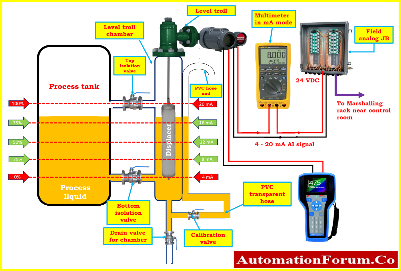
- Attach the ball valve with tee connection to both the drain isolation valve and the chamber in accordance with the calibration connection setup schematic that was presented.
- Attach the calibration ball valve with tee connection to both the drain isolation valve and the chamber in accordance with the calibration connection setup schematic that was presented.
- Get the transparent PVC hose whose length should be equivalent to the height of the level troll chamber.
- One end of the hose should be connected to the calibration ball valve, the other should be tied to the level troll chamber, and the hose should also be tied in between the two locations with chamber.
- The PVC transparent hose will be used as the reference level indicator for the calibration process.
- Attach the multimeter (mA mode) in series with an analogue input loop using probes and a lead between the junction box and the level troll.
- If it is a smart transmitter, you should further connect the HART field communicator with the level troll terminal.
- Presently, the connections have been made and are getting prepared for the calibration as shown in the diagram.
Calibration procedure
What is wet calibration?
- Verify the stability of the level troll connections.
- Check if the power supply is 24 VDC and available in the level troll terminal.
- Referring to the data sheet will help you verify a few of the parameters. The tag number, PV, LRV, and URV are examples of typical parameters.
- If it is a smart transmitter, you will be able to check the parameters using a HART communicator.
- The calibration points for the reference level from the data sheet should be marked on the chamber by standard measuring tape.
- Certain level trolls typically arrived with an external mark on the chamber’s outside in percentage.
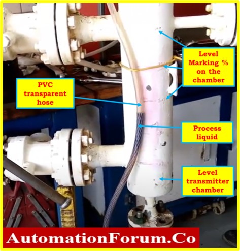
- Now, turn off the drain valve, and manually fill the chamber with the process fluid—for example, water—through the PVC hose or from the top of level troll chamber until it reaches the 0% percentage mark on the chamber.
- Using the clear reference hose and the reference marker on the level troll, gradually bring the fluid level into alignment and make it as parallel as possible.
- Now, refer to the multimeter, which should be displaying 4mA.
- If the 4mA reading is not being displayed, locate the zero adjustment on the level troll and make the necessary adjustments until the reading reads 4mA; or, use the HART Communicator to make the necessary adjustments for smart transmitter.
- Referring to the level troll manufacturer’s maintenance instruction booklet is required at all times in order to locate the zero and span adjustment in level troll.
- Fill the chamber with water using the PVC hose until the 100 percent mark on the chamber is reached.
- Bring the fluid level gradually into alignment and as close to parallel as possible.
- Refer now to the multimeter, which should be displaying 20 milliamperes (mA).
- If the 20 mA reading is not displayed, locate the level troll’s span adjustment and make the appropriate adjustments until the reading displays 20 mA; or use the HART Communicator to make the necessary adjustments for a smart transmitter.
- Do the procedure for calibrating the level troll as many times as necessary until it is calibrated to the required tolerance.
- Depending on the level troll that is being installed in the process, the calibration procedure might need to be changed. Thus, before starting, please read the instrument’s manufacturer’s instructions.
Recording calibration
- Do linearity checks at 0%, 25%, 50%, 75%, and 100% fluid level output in the upscale and downscale directions to make that the level troll is producing the correct output values.
- If the output value does not fall within an acceptable range, calibration is required. Once more, if the output values have deviated from the permitted range, the level troll needs to be repaired or replaced.
- If all output values (+/- %) fall within acceptable bounds, no further calibration is required.
- The output data should be entered in the as found/as left column of the blank calibration report.
Completion of calibration
- After the calibration has been properly accomplished, attach the calibration label to the level troll.
- When the calibration is complete, clean the equipment, store it somewhere safe, and make a note of the calibration data for later use.
- Disconnect the other setup and the level troll calibration setup.
- Everything was removed from the level control accessories in the processing area should be put back.
- Make sure the workplace is tidy.
- De-isolate the apparatus.
- Bring the signal that was blocked or bypassed back to normal. The MOS needs to be normalized in the ESD loop.
- Put the level troll back in operation and check that it is working properly.
Sample level troll Calibration Report
The following image demonstrates that a process area was used for the wet calibration of a level troll sample report of calibration.

The link below will allow you to obtain the Excel template that was used to create the level troll calibration report.
FAQ on Displacer Type Level Transmitter Calibration
Why does my displacer leveltrol not accept span when using water?
This is because water has a higher specific gravity (SG) than the process fluid.
If your process SG is 0.8 (for crude oil) and you utilize water (SG 1.0), the displacer becomes “too light,” and the transmitter sees more buoyancy than it should.
This makes the 20 mA point go too far, which means the span can’t be set.
The simple answer is that water is heavier than your process liquid, which makes the calibration wrong.
Can you calibrate a displacer level transmitter dry?
Yes, but only for a quick check.
You can set the fundamental zero/span mechanically with dry calibration, but it will never be right because there is no liquid and no buoyancy.
Final calibration must always be done with a liquid that has the right SG.
What SG should be used for calibration?
Always utilize the process liquid’s actual operating SG.
For example:
Crude oil has an SG of about 0.80 to 0.85, while water has an SG of 1.0.
For the interface level, both SG values are needed.
The calibration will be inaccurate if you use the wrong SG.
How do you calibrate interface level using a displacer?
To calibrate the interface level:
- Fill the chamber with a heavier liquid (water) and set it to 0%.
- Slowly pour the lighter liquid (oil) on top until it reaches 100%.
- Mark the interface levels according to the data sheet.
- Change the zero and span based on how the buoyancy changes between the two SGs.
To calibrate the interface correctly, you need both SG values (oil and water).
Why is my displacer level sensor giving unstable readings?
Some common reasons are:
- Changes in the SG process
- Inside the vessel, an emulsion layer is formed.
- Displacer stuck because of dirt or wax Air bubbles stuck in the cage
- Vibration that affects the torque tube
- Loose connection or worn torque tube
The reason is simple: Any change in buoyancy or anything that stops the free displacer from moving will make the readings unstable.
)