- Forward Acting Control Valve vs Reverse Acting Control Valve: Selection Guide
- What is Control Valve Action in Process Control Loop Design
- Air to Open vs Air to Close Valve Explained for Engineers
- Process Gain and Control Philosophy in Control Valve Selection
- When to Use Forward Acting Control Valve in Process Industries
- When to Use Reverse Acting Control Valve in Process Industries
- Fail Open vs Fail Close Valve Selection Criteria in Instrumentation Engineering
- Control Loop Stability and Control Valve Action Interaction
- Practical Control Valve Selection Checklist for Engineers
- Real Industrial Examples of Control Valve Action Selection
- Common Mistakes in Control Valve Action Selection
- How to Select the Right Control Valve Action
- FAQ on Choose Forward and Reverse Acting Control Valves
Forward Acting Control Valve vs Reverse Acting Control Valve: Selection Guide
Control valves are the backbone of any process control system. In industries such as oil and gas, petrochemical, power generation, and manufacturing, they act as the final control element that directly influences process variables like flow, pressure, temperature, and level.
When designing a plant in real life, engineers generally spend a lot of time choosing transmitters, setting up controllers, and adjusting PID loops. However, one of the most critical and frequently misunderstood decisions is selecting the correct control valve action.
From field experience, incorrect selection between a forward acting control valve and a reverse acting control valve can result in:
- Unstable control loops
- Opposite process response
- Poor controllability during disturbances
- Dangerous plant conditions during failure scenarios
In EPC projects, it is common to see loop performance issues traced back not to controller tuning, but to incorrect valve action or fail safe configuration. A poorly selected valve can make even a well tuned control loop behave unpredictably.
Understanding valve action is therefore not just a theoretical requirement. It is a practical necessity for safe and stable plant operation.
Calculate Control Valve Stroke Now: Control Valve Stroke Length Calculator
What is Control Valve Action in Process Control Loop Design
Control valve action tells you how the valve reacts when the controller output signal changes.
Forward Acting Control Valve Definition with Industrial Examples
A forward acting control valve:
- More output from the controller means the valve will open more.
- Signal up results in flow increase
This shows a direct link between the signal and the valve movement.
Reverse Acting Control Valve Definition and Working Principle
In a reverse acting control valve:
- Increase in controller output leads to decrease in valve opening
- Signal up results in flow reduction
This represents an inverse relationship between signal and valve movement.
How Control Valve Action Affects Process Stability and Safety
In real systems, this relationship determines how the process reacts:
- Direct relationship means controller output reinforces process increase
- Reverse relationship means controller output reduces process effect
From an instrumentation design engineering perspective, this relationship must align with process requirements. Otherwise, the system may respond in the wrong direction.
Master Forward Versus Reverse Valve Action: Working of Direct Acting and Reverse Acting Control Valve Loop
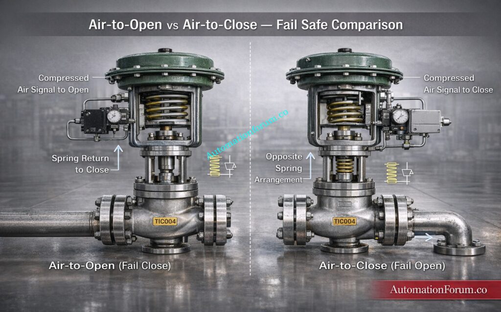
Air to Open vs Air to Close Valve Explained for Engineers
A key concept closely linked with valve action is actuator behavior.
Air to Open Valve and Fail Close Valve Working Principle
- Increasing air pressure opens the valve
- Loss of air causes the valve to close
- Known as fail close valve
Air to Close Valve and Fail Open Valve Behavior
- Increasing air pressure closes the valve
- Loss of air causes the valve to open
- Known as fail open valve
Bench Set Actuators for Fail Safe Performance: Why is Control Valve Actuator Bench Set Important ?
Difference Between Valve Action and Actuator Action
The actuator contains a spring mechanism that defines the fail position during air loss.
In practical plant design:
- Air to open is typically used when stopping flow is safer
- Air to close is used when maintaining flow is safer
Common Mistakes in Air to Open and Air to Close Valve Selection
Many engineers confuse:
- Valve action
- Controller action
- Positioner configuration
These are independent but interconnected elements. The final valve behavior depends on how all three are configured together.
Compare Control Valve Actuators Fast: Basic Types of Control Valve Actuators
Process Gain and Control Philosophy in Control Valve Selection
A fundamental concept in process control loop design is process gain.
Positive Gain Process in Flow and Pressure Control Loops
- Valve opening increases process variable
- Example: flow control loop
Negative Gain Process in Temperature and Cooling Systems
- Valve opening decreases process variable
- Example: cooling water reduces temperature
How to Select Controller Action Based on Process Gain
The controller must act opposite to the process behavior to maintain stability.
- Positive gain process → reverse acting controller
- Negative gain process → direct acting controller
Relationship Between Process Gain and Control Valve Action
This principle ensures that the controller output drives the system toward the setpoint rather than away from it.
From field experience, ignoring process gain is one of the most common reasons for loop instability.
Choose Valve Body Material Like a Pro: Control Valve Body Material Selection Guide for EPC Design Instrumentation Engineers
When to Use Forward Acting Control Valve in Process Industries
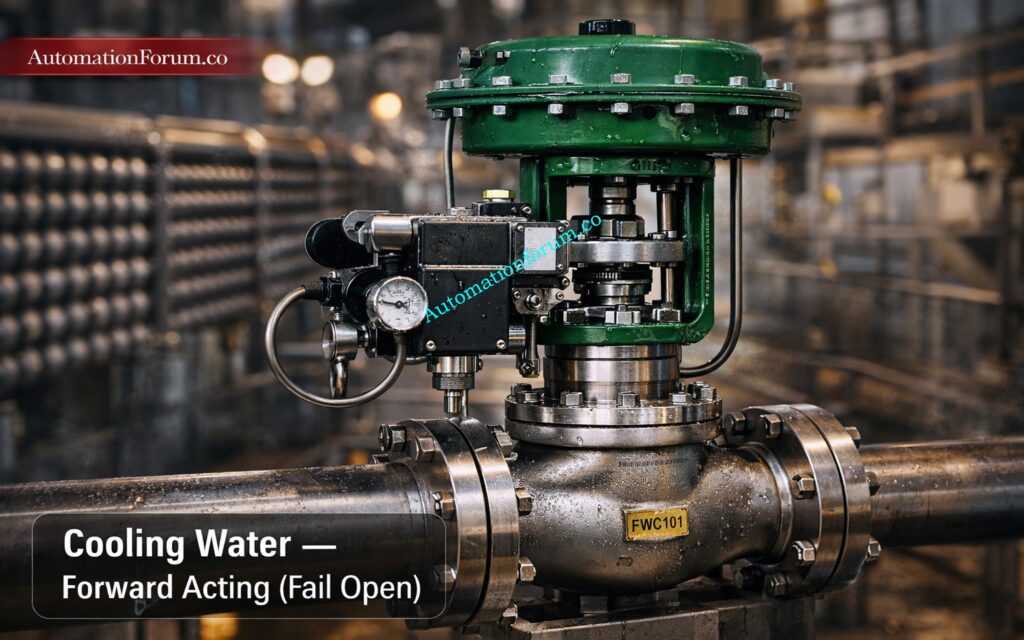
Forward Acting Control Valve in Cooling Water Systems
A forward acting control valve is selected when an increase in the control signal must result in an increase in flow or process effect. In simple terms, the valve movement follows the direction of the signal, meaning signal up leads to valve opening up. This direct relationship between controller output and valve position is fundamental in many process applications where increasing the manipulated variable helps correct the process deviation.
From an instrumentation design engineering perspective, forward acting valves are preferred in systems where the process requires immediate reinforcement of flow or removal of energy as the process variable increases.
Cooling System Control Logic Temperature Increase Flow Increase
In cooling applications, the process variable is typically temperature, and the objective is to remove heat efficiently.
- Increase in temperature requires more cooling
- Controller detects high temperature and increases output
- Valve must open to allow more cooling medium
Why Fail Open Valve is Preferred in Cooling Applications
This makes forward acting control valves highly suitable for cooling water circuits, heat exchangers, and jacket cooling systems.
In practical plant design:
- Reactor temperature rises
- Controller output increases
- Cooling water valve opens further
This ensures that heat removal increases proportionally with temperature rise.
From field experience, incorrect valve action in cooling loops often results in dangerous scenarios. If the valve closes when temperature rises, the system will move toward thermal runaway instead of stabilizing.
Pressure Increase Vent Valve Opening Strategy
In pressure control situations where venting or relief is needed:
- More discharge or venting is needed when the pressure goes up.
- As pressure goes up, the controller output goes up.
- To alleviate too much pressure, the valve must open.
Forward Acting Valve in Flare and Vent Gas Systems
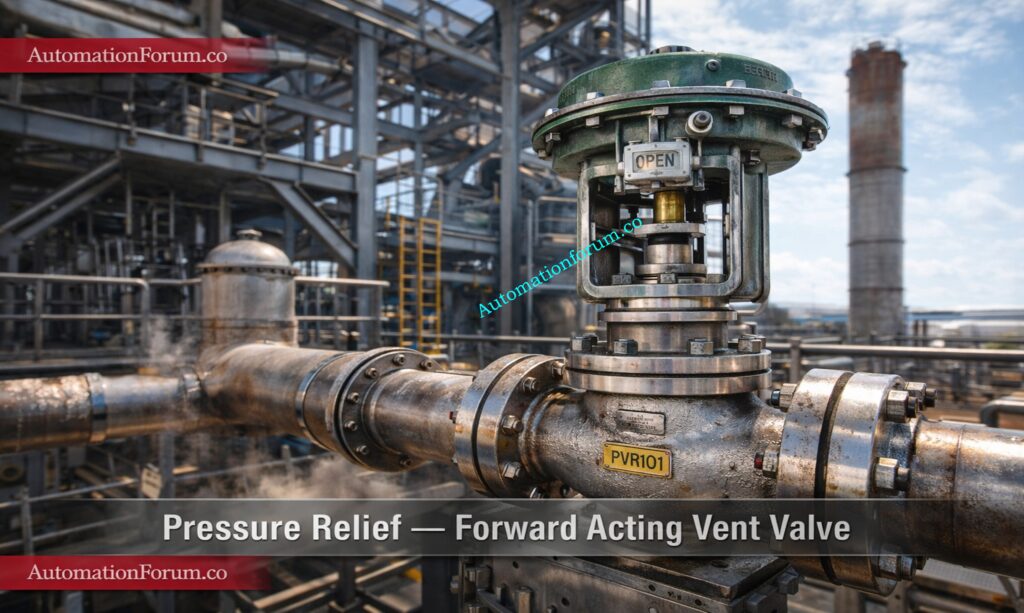
Forward-acting valves make sure that pressure is lowered promptly and effectively.
Typical applications include:
- Flare systems
- Vent gas systems
- Compressor anti surge lines
To stop pressure from building up in these systems, there must be a direct link between the signal and the valve opening.
Forward Acting Control Valve in Flow Control Applications
In standard flow control applications:
- Increase in controller output should increase flow
- Valve opening must increase proportionally
Flow Loop Design Using Direct Acting Valve
This is the most straightforward application of forward acting control valves and is widely used in:
- Feed flow control
- Transfer lines
- Utility distribution systems
Since the process gain is positive in these cases, a direct relationship between signal and flow is required for stable control.
Refer the below link for the Understand Essential Control Valve Performance Parameters
Safety Considerations for Forward Acting Control Valve Selection
One of the most critical aspects of selecting a forward acting control valve is the associated fail safe behavior.
These systems often need a fail-open valve setup, which means:
- The valve opens when the air supply is cut off.
Fail Open Valve Applications in Process Plants
Typical applications include:
- Systems for cooling water
- Lubrication systems for compressors
- Lines for emergency venting and lowering pressure
The reason is straightforward:
If the air supply fails, the safest thing to do is to keep or increase the flow, not stop it.
For example:
- Equipment can be damaged if cooling water is lost.
- Mechanical breakdown can happen if lubrication is lost.
Fail open makes sure that protection stays in place even if the instrument air fails.
Cooling and Emergency Systems Design Philosophy
In EPC design and commissioning, forward-acting valves follow a simple control logic:
- The temperature goes up, which makes the controller output go up, which opens the valve.
- When pressure goes up, the controller output goes up, and the valve opens.
This is in line with what operators expect and makes it easier to fix problems.
From what I’ve seen in the field:
- Loop behavior is easy for operators to grasp.
- Engineers who work on maintenance can find problems faster
- Loop tuning becomes easier to forecast
This clarity makes it less likely that people will make mistakes and makes the plant more reliable amid interruptions.
Stop Control Valve Hunting Today: Control Valve Hunting Due to PID Controller: Causes, Effects, Root Analysis and Complete Troubleshooting Guide for Industrial Process Control Systems
When to Use Reverse Acting Control Valve in Process Industries
When a control signal has to go up, a reverse acting control valve is used to make the flow or process effect go down. In this example, the valve moves in the opposite direction of the signal, thus when the signal goes up, the valve closes.
Most of the time, these valves are utilized in systems where adding energy or material is part of the process, and lowering the input is needed to raise the process variable.
Reverse Acting Control Valve in Heating Systems
In heating applications, the goal of the process is to keep the temperature stable by managing the amount of energy that goes in.
- If the temperature goes up, the heating needs to go down.
- The output of the controller goes up.
- To lower the amount of heat coming in, the valve must close.
Reverse acting control valves are ideal for such systems.
Typical applications include:
- Heat exchangers
- Furnaces
- Thermal oil systems
Temperature Control Logic Reduce Heat Input
In practical plant design:
- Temperature exceeds setpoint
- Controller output increases
- Steam or fuel valve closes
This reduces heat input and stabilizes the process.
Refer the below link for the What are the main causes of control valve hunting?
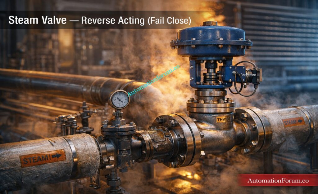
Steam Flow Control Based on Temperature Feedback
Steam is one of the most common heating media in process industries.
- Steam adds energy to the process
- High temperature requires reduction in steam flow
- Valve must close as signal increases
Reverse acting valves are therefore widely used in:
- Steam flow control
- Temperature control loops
- Reboilers and distillation columns
From engineering experience, steam valves are almost always configured as air to open valve with fail close behavior to ensure safety.
Reverse Acting Control Valve in Level Control Systems
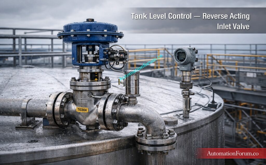
In tank level control applications:
- High level requires reduction in inlet flow
- Controller output increases
- Valve must close
Reverse acting valves are commonly used for inlet control in:
- Storage tanks
- Process vessels
- Separator units
In this case:
- Signal up leads to flow down
- Prevents overflow conditions
Safety Considerations for Reverse Acting Control Valve
Reverse acting control valves are typically associated with fail close valve configuration, meaning:
- Loss of air supply causes valve to close
This is critical in systems where continued flow can create hazards.
Typical applications include:
- Steam lines
- Fuel gas systems
- Chemical injection systems
If air supply fails:
- Valve closes
- Energy addition stops
- Hazard is minimized
This aligns with the fundamental safety principle of isolating the source of risk.
Safety Considerations for Reverse Acting Control Valve
In real plant scenarios, reverse acting logic behaves as follows:
- Temperature drops → controller increases output → valve opens
- Temperature rises → controller reduces output → valve closes
This ensures that:
- Energy input is reduced when not required
- Process remains stable around setpoint
From commissioning experience, many issues arise when reverse acting valves are incorrectly configured as forward acting.
This leads to:
- Heating increasing when temperature rises
- Rapid process instability
- Potential equipment damage
Correct selection ensures predictable and stable control loop performance.
Measure Cv to Avoid Sizing Errors: Why Measuring Control Valve Cv is Essential for Proper Valve Sizing ?
Energy Isolation Strategy in Process Design
The selection between forward acting and reverse acting control valves is not arbitrary. It must always be based on:
- Process behavior
- Energy flow direction
- Safety requirements
- Failure conditions
A simple rule used by experienced engineers:
- If process needs more flow when PV increases → use forward acting control valve
- If process needs less flow when PV increases → use reverse acting control valve
Understanding this logic in depth is what differentiates a good design engineer from a great one.
Fix Non Responding Control Valves Now: Field Troubleshooting Guide: Control Valve Not Responding in Process Area
Fail Open vs Fail Close Valve Selection Criteria in Instrumentation Engineering
Fail safe design is the most critical factor in control valve selection criteria.
Fail Open Valve Applications in Cooling and Safety Systems
Used when flow must continue during failure:
- Cooling water systems
- Fire protection systems
- Pressure relief systems
These systems prioritize safety over process efficiency.
Detect Valve Leakage Before It Kills Performance: Control Valve Leakage Testing, Types, and Calculation Standards
Fail Close Valve Applications in Heating and Hazardous Systems
Used when flow must stop during failure:
- Fuel gas systems
- Steam supply lines
- Hazardous chemical injection
Stopping flow prevents dangerous conditions.
How to Select Fail Safe Position Based on Process Risk
In instrumentation design engineering, always ask:
- What is the safest condition during failure
- Is it safer to add flow or stop flow
The choice of air to open or air to close must be based on hazard analysis, not convenience.
Run Partial Stroke Tests Confidently: What is Partial Stroke Test (PST)? A Complete Guide for Shutdown and Control Valves
Control Loop Stability and Control Valve Action Interaction
Valve action directly impacts loop stability.
Consequences of Incorrect Selection
Loop Runaway and Reverse Response Explained
If valve action is wrong:
- Controller output drives process in wrong direction
- Process variable diverges from setpoint
Oscillation Due to Incorrect Valve and Controller Action
Incorrect action leads to continuous correction:
- Controller and valve oppose each other
- Loop becomes unstable
Reverse Response
Initial response goes opposite to expectation:
- Common during commissioning
Matching Process Gain, Controller Action and Valve Action
For stable loops:
- Valve action
- Controller action
- Process gain
All must be correctly aligned.
Ignoring this relationship leads to poor control performance even with advanced controllers.
Eliminate Valve Passing After Overhaul: How to Troubleshoot a Control Valve Passing Problem after Overhauling: Complete Root Cause Analysis
Practical Control Valve Selection Checklist for Engineers
In real engineering practice, use the following checklist to ensure correct control valve action and fail safe selection:
- Identify process variable and clearly understand how it behaves under disturbance conditions
- Determine process gain sign whether it is positive or negative based on valve opening effect
- Define safest fail position based on hazard analysis and plant safety philosophy
- Decide if system is heating or cooling and whether energy is being added or removed
- Evaluate what happens during air failure since valve failure mode depends on actuator design
- Confirm controller action is properly matched with process gain and valve action
- Verify operator expectation and ensure logic is intuitive for field operation
- Check if system is safety critical such as reactor, boiler, or hazardous chemical handling
- Validate positioner configuration to avoid reverse signal interpretation during commissioning
- Review PID logic thoroughly including interlocks and shutdown conditions
- Check whether fail open or fail close is required to either maintain flow or stop flow during failure
- Ensure valve action aligns with process response during abnormal conditions and startup sequences
- Consider maintenance accessibility and ease of troubleshooting in real plant conditions
This checklist helps avoid common design, commissioning, and operational errors while ensuring that the selected valve action supports both process stability and plant safety.
Build Perfect Control Valve Datasheets: How to Prepare Control Valve Datasheets: A Step-by-Step Procedure for EPC Instrumentation Engineers
Real Industrial Examples of Control Valve Action Selection
Reactor Cooling Water Control Valve Example
The goal is to cool down the reactor.
- Valve type: air to close
- Fail position: open
Reason:
- If the temperature goes up, the cooling has to go up also.
- Fail open keeps the cooling going.
If you choose the wrong one:
- Cooling stops when there is a failure.
- The temperature of the reactor rises quickly.
- Danger of a runaway reaction
Refer the below link for the Control Valve Calibration Procedure
Steam Temperature Control Valve Example
The goal is to control the heating.
- Type of valve: air to open
- Position of failure: closed
Reason:
- Steam makes things hotter
- Fail near stops things from becoming too hot.
If you choose the wrong option:
- Even when it fails, steam keeps flowing.
- The temperature is too high.
- There is a chance of damage to the equipment.
Refer the below link for the PID controller tuning
Tank Level Control Valve Example
Objective is to maintain tank level.
Typical configuration:
- High level → valve closes
- Valve type: reverse acting
Fail position depends on process:
- Overflow risk → fail close
- Pump protection → fail open
If incorrectly selected:
- Tank overflow
- Loss of product
- Environmental hazards
Select Valves for Harsh Conditions: Control Valve Selection and Recommended Practices for Harsh Process Conditions
Common Mistakes in Control Valve Action Selection
Confusion Between Forward Acting and Reverse Acting Control Valve
A lot of engineers think they are the same.
In actual life:
- The action of the valve determines how things move.
- The action of the controller determines how the signal responds.
Mismatch leads to unstable loops.
Ignoring Fail Open and Fail Close Valve Requirements
Designers sometimes put performance ahead of safety.
This leads to:
- Unsafe circumstances in the plant when the air fails
Copy Paste Design Errors in EPC Engineering Projects
In EPC projects:
- People utilize designs again without knowing how they work.
This leads to the wrong choice of valve.
Wrong Positioner Configuration in Control Valves
Even with correct valve:
- Incorrect positioner setup reverses action
This is a common commissioning issue.
Size Control Valves to ISA Standards: Control Valve Sizing Calculator: Complete ISA S75.01 Cv Calculation Guide for Instrumentation Engineers
How to Select the Right Control Valve Action
Choosing between a forward acting control valve and a reverse acting control valve is a fundamental decision in instrumentation design engineering.
It directly affects:
- Process safety
- Loop stability
- Plant reliability
From field experience, the best engineers do not rely on memorized rules. They analyze:
- Process behavior
- Energy addition or removal
- Failure scenarios
A properly chosen valve makes sure that:
- Control loops that stay the same
- Response to the procedure that can be predicted
- Safe operation under unusual situations
In the end, it’s more crucial to understand the process than to choose the valve. The valve action must always follow the process logic, not the other way around.
Predict Control Valve Noise Instantly: Control Valve Noise Prediction Calculator – IEC 60534 Based Engineering Tool
FAQ on Choose Forward and Reverse Acting Control Valves
What is a reverse acting control valve?
A reverse acting control valve is a type of valve that closes and slows down flow when the control signal goes up.
It is usually utilized in systems for heating or adding energy where the flow needs to go down as the process variable goes up.
What is the difference between direct and reverse acting valves?
A direct acting valve opens when the signal gets stronger, and a reverse acting valve closes when the signal gets stronger.
The main distinction is how the valve reacts to the control signal and how it behaves when it fails.
Calculate Equal Percentage Flow Now: Equal Percentage Control Valve Flow Calculator
How to select the right control valve?
Select the right control valve based on process gain, fail safe requirement, and whether the system needs heating or cooling.
Always evaluate what happens during air failure and ensure valve action matches process control logic.
What is the difference between PCV and LCV?
A PCV controls and maintains system pressure, while an LCV controls liquid level in tanks or vessels.
The difference is based on the process variable being controlled pressure versus level.
What is the rule of thumb for control valve sizing?
A common rule is to size the control valve so it operates around 60 to 80 percent opening at normal conditions.
This ensures good controllability, avoids cavitation, and allows margin for process variation.
Equip Valves with Must Have Accessories: Essential Control Valve Accessories for Reliable Process Control
What is the purpose of a reverse acting control?
The purpose of reverse acting control is to reduce process input when the process variable increases.
It helps maintain stability in systems where increasing output must decrease flow or energy.
Calculate Valve Opening Percentage Now: Control Valve Opening Percentage Calculator for Precise Flow Control Rate Adjustment