- Control Valve Noise in Process Industries
- Control Valve Noise Prediction Calculator
- What Is a Control Valve Noise Prediction Calculator?
- Why Control Valve Noise Calculation Is Critical
- International Standards Governing Control Valve Noise
- Types of Control Valve Noise Covered by the Calculator
- Aerodynamic Noise in Control Valves
- Hydrodynamic Noise in Control Valves
- Cavitation Index (σ) and Valve FL Factor
- Flashing Flow Detection in Control Valves
- Distance Correction for Noise Measurement
- How the Control Valve Noise Calculator Works
- Step 1: Input Process and Valve Data
- Step 2: Acoustic Power Calculation
- Step 3: Pipe Transmission Loss
- Step 4: Distance Correction and Final SPL
- Understanding the Noise Spectrum Graph
- How to Use the Control Valve Noise Calculator
- Step-by-Step Usage Guide for Control Valve Noise Calculator
- Who Should Use This Control Valve Noise Calculator?
- Practical Applications in Process Plants
- Advantages of This Control Valve Noise Calculator
- Control Valve Noise Calculation – Frequently Asked Questions (FAQ)
Control Valve Noise in Process Industries
Control valves are one of the most important parts of any process plant. They can control flow, pressure, and temperature, but if they aren’t chosen or designed correctly, they can also make a lot of noise. Too much noise from control valves isn’t just annoying; it’s a big safety, reliability, and compliance problem.
Engineers can use the Control Valve Noise Prediction Calculator to get an accurate estimate of how much noise a valve will make during the design, review, and operating stages of a project. This calculator lets you make smart choices before problems reach the plant floor by forecasting noise levels in dB(A) using IEC 60534 methods.
Control Valve Noise Prediction Calculator
Your Trusted Source for Automation Power Tools & Solutions
Control Valve Noise Prediction Tool (IEC 60534)
Aerodynamic Noise – Gas / Steam
Hydrodynamic Noise – Liquid
What Is a Control Valve Noise Prediction Calculator?
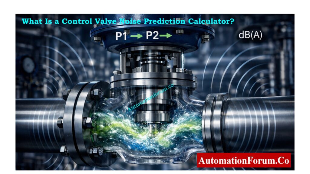
A control valve noise prediction calculator is an engineering tool that figures out how much sound pressure level a control valve will make depending on things like the pressure drop, flow rate, fluid type, and piping shape.
This calculator checks:
- Aerodynamic noise for gas and steam services
- Hydrodynamic noise for liquid services
- Cavitation and flashing conditions
- Noise propagation through piping
- Occupational safety limits
The output is measured in dB(A), which is the standard unit in the industry for measuring how much noise people are exposed to.
Sizing Accuracy Starts Here – Why Measuring Control Valve Cv is Essential for Proper Valve Sizing ?
Why Control Valve Noise Calculation Is Critical
Impact of Excessive Valve Noise
Uncontrolled valve noise can cause:
- Permanent hearing loss for operators
- Too much vibration in pipe systems
- Failure of downstream pipe due to fatigue Erosion of valve trim at a faster rate
- More repairs and unforeseen shutdowns
- Not following safety rules at work
Most international safety guidelines say that 85 dB(A) is the most level of continuous exposure that workers can have. Engineering controls or personal protective equipment are needed for anything over this level.
Stop Valve Instability – What are the main causes of control valve hunting?
International Standards Governing Control Valve Noise
IEC 60534 Noise Standards
The calculator is structured around internationally recognized standards:
IEC 60534-8-3 – Aerodynamic Noise
- Works for steam and gas control valves
- Looks at noise created by gas flow that is turbulent and fast.
- A lot of the time, people use it in steam systems, natural gas pipelines, and compressed air services.
IEC 60534-8-4 – Hydrodynamic Noise
- This applies to valves that control liquids.
- Includes turbulence, cavitation, and flashing noise
- Used a lot in services for boiler feedwater, cooling water, and hydrocarbons
These guidelines give all industries a clear and consistent way to predict noise.
Precision & Control Explained – Why You Should Use Control Valve Positioners?
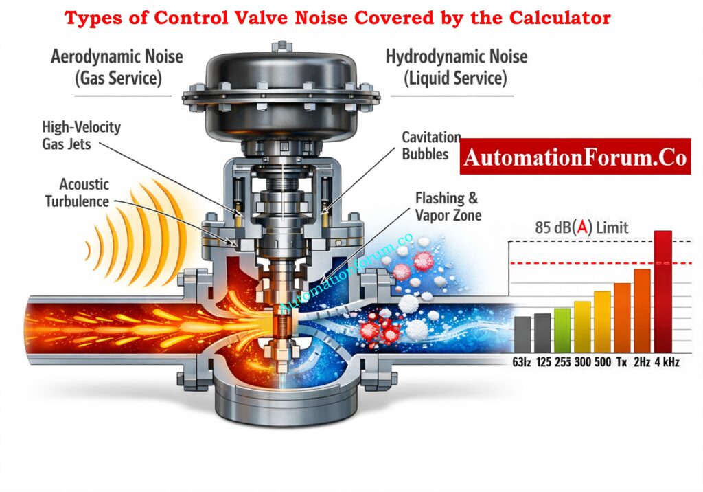
Types of Control Valve Noise Covered by the Calculator

Aerodynamic Noise in Control Valves
What Is Aerodynamic Noise?
When gas or steam goes through a valve with a big pressure drop, it makes high-speed jets and turbulent eddies downstream of the trim. This is called aerodynamic noise.
Typical Aerodynamic Noise Applications
- Valves that lower steam pressure
- Valves for controlling the flow of natural gas
- Valves for recycling compressors
- Control valves for venting and blowing down
The calculator uses pressure drop, flow rate, and pipe diameter to figure out the sound pressure level in dB(A) that will come from the aerodynamic noise.
Leakage Testing Demystified – Control Valve Leakage Testing, Types, and Calculation Standards
Hydrodynamic Noise in Control Valves
What Is Hydrodynamic Noise?
When flow turbulence, cavitation, or flashing happens inside or downstream of the valve, hydrodynamic noise happens in liquid services.
Typical Hydrodynamic Noise Applications
- Valves for controlling boiler feedwater
- Valves for controlling cooling water
- Services for hydrocarbon liquids
- Recirculation valves for minimum flow pumps
Hydrodynamic noise is frequently worse than aerodynamic noise since it can cause actual erosion and vibration, not just noise that you can hear.
Built for Extreme Services – Control Valve Selection and Recommended Practices for Harsh Process Conditions
Cavitation Index (σ) and Valve FL Factor
What Is Cavitation in Control Valves?
When the pressure in a liquid drops below its vapor pressure, vapor bubbles form and then rapidly collapse. This is called cavitation. This event causes loud noise, vibration, and damage to metal.
Cavitation Index (σ)
The calculator uses the inlet pressure, output pressure, and vapor pressure to figure out the cavitation index (σ).
Valve FL (Pressure Recovery Factor)
- FL shows how rapidly pressure comes back downstream of the valve.
- Every valve design has a unique FL value.
- By comparing σ to FL, you can figure out how bad cavitation is.
Cavitation Classification
- No cavitation
- Incipient cavitation
- Developed cavitation
This classification helps engineers figure out if a conventional trim will work or if a specific anti-cavitation trim is needed.
Must-Have Components – Essential Control Valve Accessories for Reliable Process Control
Flashing Flow Detection in Control Valves
What Is Flashing?
Flashing happens when the pressure downstream stays below the liquid’s vapor pressure, which means that vapor bubbles don’t pop. This makes two-phase flow happen all the time, which makes noise and erosion a lot worse.
How the Calculator Handles Flashing
- Compares outlet pressure with saturation pressure
- Flags flashing conditions clearly
- Applies higher acoustic power factors to reflect real plant behavior
Flashing conditions almost always require special valve designs or downstream diffusers.
Distance Correction for Noise Measurement
Why Distance Matters in Noise Prediction
As you go away from the source, the noise gets quieter. Engineers can use the calculator to measure noise at real-world locations, not simply at the valve body.
Available Noise Locations
- 1 meter (standard reference distance)
- 3D downstream
- 6D downstream
This is particularly useful for:
- Operator walkways
- Control room boundaries
- Maintenance access platforms
Performance That Matters – Essential Control Valve Performance Parameters
How the Control Valve Noise Calculator Works
Step 1: Input Process and Valve Data
Users enter:
- Inlet pressure (P₁)
- Outlet pressure (P₂)
- Flow rate (gas or liquid)
- Pipe inside diameter
- Saturation pressure (for liquids)
- Valve FL value
Accurate inputs ensure reliable noise predictions.
Step 2: Acoustic Power Calculation
The calculator computes acoustic power generated by the valve based on:
- Flow energy
- Pressure drop
- Fluid behavior (compressible or incompressible)
Separate equations are used for aerodynamic and hydrodynamic noise.
Step 3: Pipe Transmission Loss
Noise radiated to the environment depends on pipe size and stiffness.
- Larger pipes radiate less noise
- Smaller pipes amplify noise
The calculator applies pipe transmission loss corrections to reflect this behavior.
Step 4: Distance Correction and Final SPL
Distance correction is applied to convert sound power into sound pressure level at the selected location.
The final result is displayed as:
- Sound Pressure Level – dB(A)
- Safety classification (SAFE / CAUTION / UNSAFE)
Sizing Done Right – How to Properly Size Control Valves for Maximum Efficiency?
Understanding the Noise Spectrum Graph
What the Spectrum Represents
The calculator generates a noise spectrum across octave bands:
- 63 Hz
- 125 Hz
- 250 Hz
- 500 Hz
- 1 kHz
- 2 kHz
- 4 kHz
These bands help identify dominant frequencies.
Y-Axis Unit Explained
- Y-axis unit: dB(A)
- Represents A-weighted sound pressure level
- Reference pressure: 20 µPa
A red dashed line indicates the 85 dB(A) occupational safety limit.
Troubleshooting Made Easy – Field Troubleshooting Guide: Control Valve Not Responding in Process Area
How to Use the Control Valve Noise Calculator
Step-by-Step Usage Guide for Control Valve Noise Calculator
Step 1: Choose the Noise Type
- Aerodynamic section for gas or steam
- Hydrodynamic section for liquid services
Step 2: Enter All Required Inputs
Ensure all pressure, flow, and pipe values are entered correctly.
Step 3: Run the Calculation
- Noise level
- Safety classification
- Cavitation and flashing status
Step 4: Review the Noise Spectrum
Identify problematic frequency bands and safety risks.
Step 5: Export Results to Excel
Download a structured Excel report for documentation and sharing.
Safety & Shutdown Explained – What is Partial Stroke Test (PST)? A Complete Guide for Shutdown and Control Valves
Who Should Use This Control Valve Noise Calculator?
Instrumentation and Control Engineers
- Valve sizing and selection
- Noise compliance verification
Process Engineers
- Design-stage risk analysis
- Process optimization
Mechanical and Piping Engineers
- Vibration and fatigue prevention
- Silencer and insulation design
Safety and HSE Engineers
- Occupational noise exposure assessment
- Regulatory compliance reviews
EPC Contractors and Consultants
- Project documentation
- Client design submissions
Post-Overhaul Problems Solved – How to Troubleshoot a Control Valve Passing Problem after Overhauling: Complete Root Cause Analysis
Practical Applications in Process Plants

Control Valve Selection and Specification
Avoid selecting valves that exceed acceptable noise limits under normal operation.
Noise Mitigation Planning
Determine the need for:
- Low-noise trims
- Multi-stage pressure reduction
- Acoustic insulation
- Downstream silencers
FAT, SAT and Design Reviews
Validate predicted noise levels before equipment installation.
Training and Engineering Education
Demonstrate how pressure drop, flow, and piping affect noise generation.
EPC Engineer’s Practical Guide – How to Prepare Control Valve Datasheets: A Step-by-Step Procedure for EPC Instrumentation Engineers
Advantages of This Control Valve Noise Calculator
- Web-based and easy to use
- Methodology based on IEC that is clear
- No need for tools from a specific vendor
- A visual representation of the noise spectrum
- Excel report export
- Suitable for early design and screening studies
The Control Valve Noise Prediction Calculator is a great tool for engineers to make sure that process plants run safely, legally, and reliably. The program helps you choose the best valve, design it more safely, and lower the cost of the whole life cycle by forecasting both aerodynamic and hydrodynamic noise, finding cavitation and flashing dangers, and showing noise spectra.
This calculator is a must-have for engineers who work in process industries to use while designing and keeping things safe.
Refer the below link for the Control Valve Calibration Procedures
Control Valve Noise Calculation – Frequently Asked Questions (FAQ)
What is the noise limit for control valves?
According to IEC, ISO, and occupational safety recommendations, the noise limit for control valves is 85 dB(A) measured 1 meter away from the valve or piping.
Typical Control Valve Noise Limits:
- ≤ 80 dB(A): Acceptable – no action required
- 80–85 dB(A): Caution – hearing protection recommended
- > 85 dB(A): Unsafe – noise mitigation required
In places where machines run all the time, being around sounds louder than 85 dB(A) for a long time can damage your hearing for good. Because of this, people usually use IEC 60534 noise calculation methods to figure out how loud control valves will be during the design stage.
How to tell if valves are noisy?
A control valve is deemed loud if it makes sounds, vibrations, or strange acoustic characteristics while it is working.
Common Signs of a Noisy Control Valve:
- A loud hissing or roaring sound (for gas or steam supply)
- Noise that sounds like crackling or rattling (liquid cavitation)
- Vibration of the pipe after the valve
- The noise level goes up when the valve opens or the pressure drops.
- People who work near the valve need to wear hearing protection.
The best approach to be sure if a valve is making noise is to measure the sound pressure level (dB(A)) or use a control valve noise calculation tool to guess how loud it will be when it’s in use.
How to reduce control valve noise?
You can lower control valve noise by using low-noise or multi-stage trims, lowering pressure drop, raising downstream pressure, adding silencers or diffusers, insulating pipes, or choosing a valve that is the right size.
How to know if a control valve is bad?
A “bad” control valve doesn’t always indicate that it has broken; it could also mean that it doesn’t work well or that it is the wrong size.
Symptoms of a Bad Control Valve:
- Too much noise or vibration
- Control that isn’t stable or hunting
- The valve isn’t letting enough flow through.
- Pressure drop that isn’t normal
- Damage to the trim or need for frequent maintenance
- Flashing or cavitation that happens normally
If the calculated noise, cavitation index (σ), or operating Cv is much outside of permissible limits, it usually means that the valve was not chosen or sized correctly, not only that it is worn out.
What can cause valve noise?
High pressure drop, high fluid velocity, turbulence, cavitation, flashing, blocked flow, or the wrong size of the valve can all make noise. Bad pipe layout and not enough straight length downstream can also make noise levels go up.
What is rated Cv and calculated Cv?
Rated Cv is the highest flow rate that a valve can handle, as stated by the manufacturer. Calculated Cv is the Cv that the process needs to fulfill flow and pressure conditions. If the rated and calculated Cv are very different, it can be hard to regulate the valve and it can make a lot of noise.
Refer the below link for the Top Essential Control Valve Calculators and Excel Tools for Instrumentation Engineers
 levels, and safety limits)