
Engineering Calculators
Intrinsic Safety Entity Parameter Calculator
Verify entity concept compatibility between a safety barrier / associated apparatus and a field device (intrinsically safe apparatus), including cable reactance.
1Source Side — Barrier / Associated Apparatus
Output entity parameters of the safety barrier, isolator, or associated apparatus (from its certificate / datasheet).
2Load Side — Field Device (Ex ia / Ex ib Apparatus)
Maximum input entity parameters of the intrinsically safe field device (transmitter, switch, positioner, etc.).
3Cable Parameters
Interconnecting cable reactance is added to the field device values before comparing against Co / Lo.
4Results
| Parameter | Barrier (Source) | Condition | Device + Cable (Load) | Margin | Result |
|---|
- The barrier and field device combination must also be verified via matching hazardous area Gas Group (IIA/IIB/IIC), Temperature Class (T1–T6), and Equipment Protection Level (ia/ib) on both certificates.
- When Lo/Ro ratio is specified instead of Lo, the cable and device L/R ratio must be checked against the barrier’s L/R limit.
- For FISCO / FNICO fieldbus systems, use the dedicated FISCO entity parameters, not the general entity model above.
- Always confirm final loop calculations against the manufacturer’s control drawing and the installation’s approved system documentation.
- Intrinsic Safety Entity Parameter Verification for Hazardous Area Instrumentation
- What is an Intrinsic Safety Entity Parameter Calculator?
- Why Intrinsic Safety Entity Parameter Verification is Important
- IEC 60079 Standards for Intrinsic Safety Loop Design
- Intrinsic Safety Entity Parameter Calculator Inputs Explained
- Cable Capacitance, Cable Inductance, Cable Length, and Ignore Cable Option
- How the Intrinsic Safety Entity Parameter Calculator Works
- Automatic Output Power Calculation
- Automatic Unit Conversion
- Cable Capacitance Calculation
- Cable Inductance Calculation
- Total Loop Reactance Calculation
- Entity Parameter Compatibility Checks
- Final Compatible or Not Compatible Decision
- Practical Intrinsic Safety Calculation Example for a Refinery
- Intrinsic Safety Loop Design Best Practices
- Common Intrinsic Safety Design Mistakes Engineers Should Avoid
- Applications of the Intrinsic Safety Entity Parameter Calculator
- Frequently Asked Questions about Intrinsic Safety Entity Parameters
- What is the concept of intrinsic safety entity?
- Is IEC 60079 related to intrinsic safety?
- What are the requirements for intrinsically safe systems?
- What is intrinsic safety calculation?
- Is a 4 to 20 mA loop intrinsically safe?
- What are the levels of intrinsic safety?
- Why is cable capacitance and inductance important in intrinsic safety?
- What is the difference between a Zener Barrier and a Galvanic Isolator?
- Can multiple field devices be connected to one intrinsically safe loop?
- Can an Intrinsic Safety Entity Parameter Calculator replace manufacturer control drawings?
Intrinsic Safety Entity Parameter Verification for Hazardous Area Instrumentation
Designing an intrinsically safe instrumentation loop involves much more than selecting a certified field instrument and connecting it to a safety barrier.All parts of the loop, including the accompanying equipment, field device, and interconnecting cable, must operate in unison without contributing enough electrical energy to create a hazardous environment. This verification process is one of the most important engineering activities during the design, installation, and commissioning of hazardous area instrumentation systems.
An Intrinsic Safety Entity Parameter Calculator simplifies this verification by comparing the electrical characteristics of the safety barrier or galvanic isolator with those of the connected field device while also considering the effect of cable capacitance and inductance. This enables engineers to quickly assess whether the suggested loop is consistent with the entity concept criteria, without having to perform several manual computations, prior to installation. The calculator you uploaded will do these comparisons automatically . Voltage , current , power , capacitance and inductance checks . It will give you a compatibility judgment depending on the values you entered .
Engineering calculators reduce computation time, human errors and increase design consistency.
What is an Intrinsic Safety Entity Parameter Calculator?
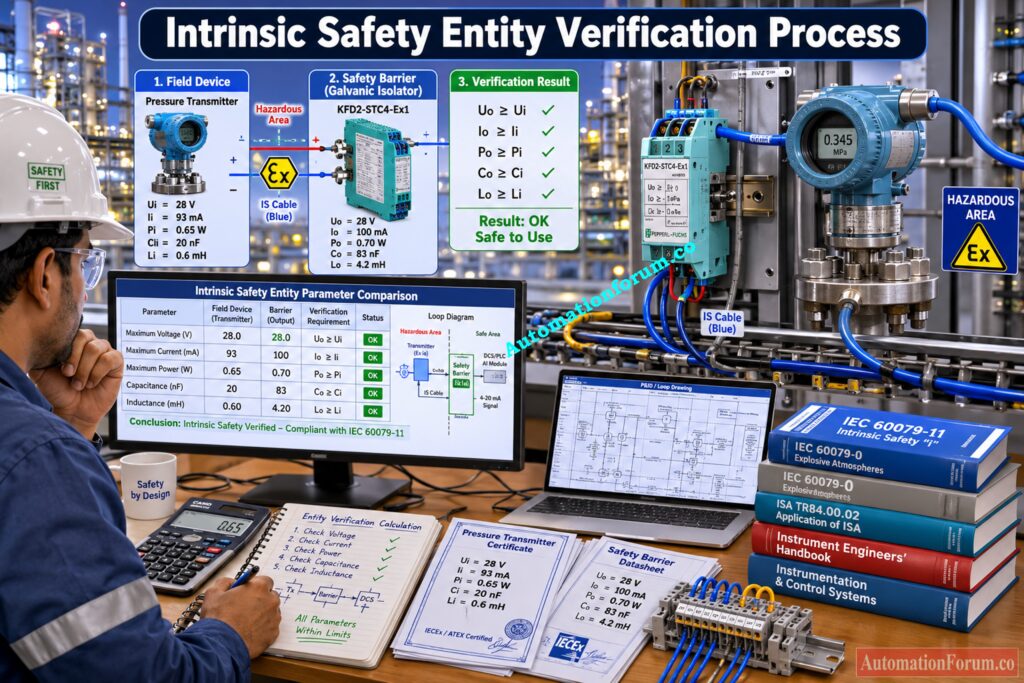
An Intrinsic Safety Entity Parameter Calculator is an engineering design tool used to verify whether a hazardous area field device can be safely connected to an intrinsically safe barrier or galvanic isolator using the Entity Concept defined by international intrinsic safety standards.
The Entity Concept is based on a simple engineering principle. Every associated apparatus has maximum electrical output limits, while every intrinsically safe field device has maximum electrical input limits. A safe installation exists only when the output capability of the associated apparatus never exceeds what the field device can safely withstand.
The verification process does not stop with voltage, current, and power. Engineers must also evaluate the total capacitance and inductance of the complete loop because stored electrical energy in cables and field devices can become an ignition source under fault conditions. Even when the barrier and transmitter appear individually compatible, excessive cable capacitance or inductance can invalidate the installation.
Modern engineering calculators automate these comparisons translating engineering units, calculating cable reactance, aggregating cable and field device characteristics and evaluating each of the entity requirements against the permitted limits before delivering a compatible or not compatible answer. This approach significantly reduces engineering effort while improving calculation accuracy.
Discover Which Protection Level Truly Matches Your Hazardous Area: Intrinsic Safety Protection Systems: Understanding Ex ia, Ex ib, and Ex ic
Why Intrinsic Safety Entity Parameter Verification is Important
Entity parameter verification is a mandatory engineering activity because intrinsic safety depends on limiting electrical energy under both normal operating conditions and specified fault conditions. Selecting incompatible equipment can introduce excessive voltage, current, or stored electrical energy into a hazardous location, creating a potential ignition source.
One common mistake during loop design is verifying only the operating voltage while ignoring output power or cable reactance. In practice, long field cables can contribute significant capacitance and inductance to the loop. These values are added to the internal capacitance and inductance of the field device before comparing them with the maximum external capacitance and inductance permitted by the associated apparatus. Failure to consider these cable characteristics may result in an installation that does not comply with intrinsic safety requirements.
Proper verification of the entity also promotes the compliance to hazardous area certification standards and eliminates the possibility of design changes during the execution of the project. This enables engineers to detect poor barrier and device combinations early in the design stage, avoiding expensive field revisions during construction or commissioning.
Most importantly, successful entity verification contributes to explosion protection by ensuring that the complete intrinsic safety loop remains within certified energy limits throughout its operating life. It forms a critical part of safe hazardous area instrumentation design and should always be completed before the loop is approved for installation.
Think You’re an IS Expert? Prove It Now: Advanced Quiz on Intrinsic Safety Instrumentation Circuits in Oil & Gas Process Industries
IEC 60079 Standards for Intrinsic Safety Loop Design
Intrinsic safety is one of the most widely accepted explosion protection techniques for electrical instrumentation installed in hazardous areas. While an engineering calculator makes entity parameter verification faster and more consistent, the calculations are meaningful only when they are applied in accordance with recognized international standards. These standards define how equipment is certified, how intrinsically safe circuits are designed, and how installations should be inspected before being placed into service.
IEC 60079 11 Requirements for Intrinsically Safe Equipment
IEC 60079 11 is the primary product standard for intrinsically safe equipment and associated apparatus. It specifies the design, testing, construction, and certification requirements for equipment intended for hazardous locations where explosive gases may be present.
From an instrumentation engineer’s perspective, this standard defines the entity parameters that appear on equipment certificates and nameplates. Parameters such as Uo, Io, Po, Co, Lo, Ui, Ii, Pi, Ci, and Li are established according to the testing methods described in this standard. These certified values become the basis for every intrinsic safety loop calculation.
When selecting a transmitter, pressure switch, temperature transmitter, valve positioner, or safety barrier, engineers obtain these values directly from the manufacturer’s certification documents prepared in accordance with IEC 60079 11.
IEC 60079 14 Requirements for Intrinsically Safe Installation
While IEC 60079 11 focuses on equipment certification, IEC 60079 14 explains how certified equipment should be selected and installed in hazardous locations.
For instrumentation engineers, this is one of the most important installation standards because it describes practical requirements for intrinsic safety loop design, including cable selection, segregation, grounding practices, equipment matching, documentation, inspection, and verification.
The standard emphasizes that entity parameter verification must consider the complete circuit rather than individual devices. This includes the associated apparatus, field instrument, interconnecting cable, junction boxes, and all other components forming the intrinsic safety loop.
Following IEC 60079 14 helps ensure that a loop which is theoretically compatible also remains safe after installation in the field.
ANSI ISA 60079 11 Standard Explained
ANSI ISA 60079 11 is the North American adoption of the international intrinsic safety equipment standard. Although the technical requirements closely follow IEC 60079 11, it provides a harmonized framework widely used across the United States and many multinational industrial projects.
Engineers working on global EPC projects frequently encounter equipment certified under both IEC and ANSI ISA standards. Understanding the relationship helps to avoid confusion while studying the certification documentation of different manufacturers.
The entity parameters used in intrinsic safety calculations remain the same regardless of whether the equipment carries IEC or ANSI ISA certification, provided the approvals are applicable to the project requirements.
ISA RP12.06.01 Recommended Practice for Intrinsic Safety
ISA RP12.06.01 provides recommended practices for applying intrinsically safe systems in hazardous locations. Unlike product certification standards, it offers practical engineering guidance for designing, documenting, verifying, installing, and maintaining intrinsic safety loops.
Experienced engineers often use this document during detailed engineering because it explains common application practices, documentation requirements, wiring considerations, and verification procedures that support safe installation throughout the project lifecycle.
it also emphasizes the need to verify factory control drawings rather than relying on numerical computations alone.
Intrinsic Safety Entity Parameter Calculator Inputs Explained
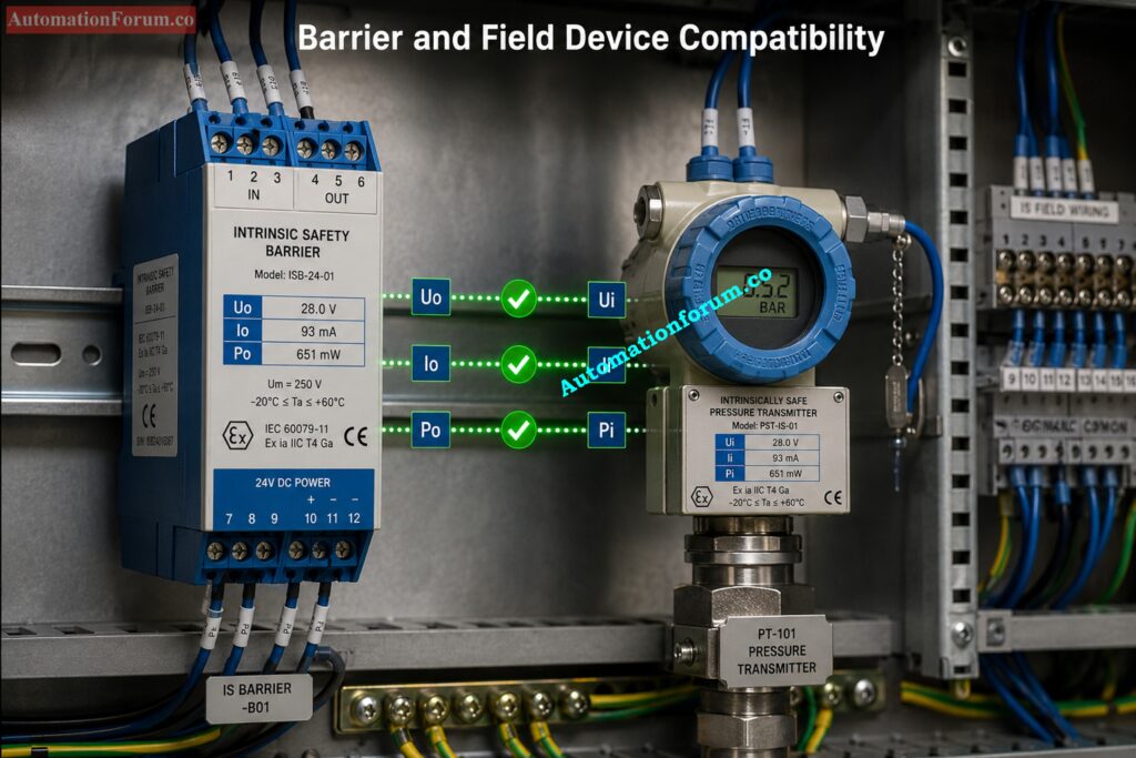
Understanding every input parameter is essential because incorrect data can lead to an unsafe engineering decision. The calculator requires both source side and field device parameters together with cable characteristics to evaluate intrinsic safety compatibility.
Uo Open Circuit Voltage
Uo is the maximum open circuit output voltage provided by the intrinsic safety barrier or galvanic isolator.
This number is the maximum voltage which can be developed at the hazardous area terminals under defined circumstances.
It is obtained directly from the barrier certificate or manufacturer datasheet.
A common mistake is using the normal operating voltage instead of the certified maximum output voltage.
Io Short Circuit Current
Io is the maximum short circuit output current available from the associated apparatus.
It defines the highest current that could be delivered during a fault condition.
The value is taken from the barrier certification documents.
Using normal loop current instead of the certified Io value is a frequent design error.
Po Maximum Output Power
Po is the maximum output power available from the associated apparatus.
If this value is not entered, the calculator automatically determines it from the certified voltage and current using the standard intrinsic safety relationship implemented in the calculator logic.
Engineers should always compare the calculated or certified Po with the field device input power rating.
Co Maximum External Capacitance
Co is the maximum external capacitance that the associated apparatus can safely drive.
This value is specified in the equipment certificate and is usually expressed in microfarads or nanofarads.
The specified unit is automatically converted by the calculator before the compatibility check.
Lo Maximum External Inductance
Lo is the maximum external inductance allowed by the linked equipment.
Like Co, it is given in the certification paperwork and can be represented in millihenries or microhenries.
Correct unit conversion is very important since wrong units might effect the final outcome to a large extent.
Ui Maximum Input Voltage
Ui is the highest input voltage that the intrinsically safe field device may safely withstand.
Typical sources include transmitter, switch, analyzer, or valve positioner certificates.
The barrier output voltage must never exceed this value.
Ii Maximum Input Current
Ii is the maximum input current accepted by the field device.
It is obtained from the intrinsic safety certificate and compared directly with the barrier output current.
Confusing operating current with certified input current is a common engineering mistake.
Pi Maximum Input Power
Pi represents the maximum input power permitted for the field device.
This number is validated by the manufacturer and ensures that the equipment can not be energized enough to constitute an ignition source.
Ci Internal Capacitance
Ci is the internal capacitance of the field device, while Li is its internal inductance.
Both values are supplied in the intrinsic safety certificate and contribute to the total stored electrical energy of the loop.
Number of Field Devices
Some intrinsically safe loops contain more than one certified field device.
The calculator allows engineers to specify the total number of devices so that cumulative capacitance and inductance are included in the verification.
Everything Every Instrument Engineer Should Know Before Designing: What is Intrinsic Safety? Definition, Working Principle, Standards and Applications
Cable Capacitance, Cable Inductance, Cable Length, and Ignore Cable Option
Every instrumentation cable contributes additional capacitance and inductance to the intrinsic safety loop. This calculator calculates these values based on the supplied cable characteristics and cable length and adds those values to the field device parameters .
Avoid Dangerous Design Mistakes With the Right Protection Method: Why select Intrinsic safety?
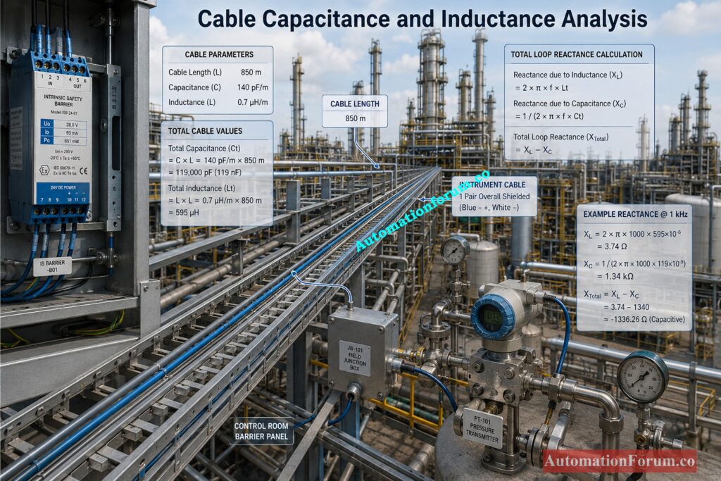
How the Intrinsic Safety Entity Parameter Calculator Works
An Intrinsic Safety Entity Parameter Calculator performs much more than a simple comparison of barrier and field device ratings. It follows the same engineering verification process that an instrumentation engineer would normally perform manually during loop design. By automating calculations and unit conversions, the calculator reduces the possibility of arithmetic errors while ensuring that every critical entity parameter is evaluated before the loop is accepted.
The calculator begins by collecting the output entity parameters of the associated apparatus, followed by the input entity parameters of the intrinsically safe field device and finally the characteristics of the connecting cable. It then performs a series of engineering calculations before issuing a final compatibility decision.
Prevent Costly Audit Findings Using This Proven Inspection Guide: Advanced Safety Instrumented System (SIS) Inspection Checklist for IEC 61511 Compliance
Automatic Output Power Calculation
Many manufacturer certificates specify the maximum output power of the associated apparatus. However, some engineering documents provide only the maximum open circuit voltage and maximum short circuit current.
To simplify verification, the calculator automatically determines the output power whenever the Po field is left blank. It applies the intrinsic safety relationship
Po = (Uo × Io) ÷ 4
where the current is converted from milliamperes to amperes before calculating power. This computerized calculation permits engineers to carry out the verification even when the approved output power is not directly available.
See How Modern Machines Prevent Serious Workplace Injuries Instantly: Safety Light Curtain Working Principle: How Does a Safety Light Curtain Work?
Automatic Unit Conversion
Engineering units used on intrinsic safety certificates often vary between equipment manufacturers.
One barrier certificate may represent capacitance in microfarads , the other in nanofarads . Inductance may also be represented in millhenries or microhenries.
To prevent human conversion errors, the calculator automatically converts all capacitance values to nanofarads and all inductance values to microhenries before any comparison. This uniformity offers a common technical unit on which all calculations can be based.
Master Functional Safety Concepts That Every Engineer Should Know: What is SIS, SIF and SIL? An In-Depth Guide to Functional Safety
Cable Capacitance Calculation
Instrumentation cable is not electrically neutral. Every meter of cable contributes additional capacitance to the intrinsic safety loop.
The calculator determines the total cable capacitance using
Cable Capacitance = Cable Capacitance per Meter × Cable Length
The resulting value is scaled to the same technical unit as the field device capacitance and added to the loop total. Long cable runs can greatly increase total capacitance, notably in refinery tank farms, offshore platforms and pipeline systems where cable lengths might be several hundred metres.
Simplify Hazardous Area Fieldbus Design Without Compromising Safety: Fieldbus Intrinsically Safe Concept (FISCO) Model for Foundation Fieldbus H1 and Profibus PA
Cable Inductance Calculation
The interconnecting cable also contributes inductance.
The calculator multiplies the cable inductance per meter by the total cable length to determine the overall cable inductance.
Although cable inductance is generally less significant than capacitance for many instrumentation loops, it becomes increasingly important for long field installations and should never be ignored during detailed engineering.
Refer the below link for the Top Causes of Intrinsically Safe (IS) Loop Failure and How to Avoid Them
Total Loop Reactance Calculation
After calculating the cable contribution, the calculator combines it with the internal capacitance and inductance of the field device.
When multiple certified field devices are connected within the same intrinsically safe circuit, the calculator first multiplies the device capacitance and inductance by the number of devices before adding the cable values.
This produces the total capacitance and total inductance of the complete intrinsic safety loop, which are then compared against the allowable limits specified by the associated apparatus.
Choose the Right Cable Before Your Project Faces Rework: Intrinsically Safe Cables for ATEX Zones – Complete Checklist for EPC Engineers
Entity Parameter Compatibility Checks
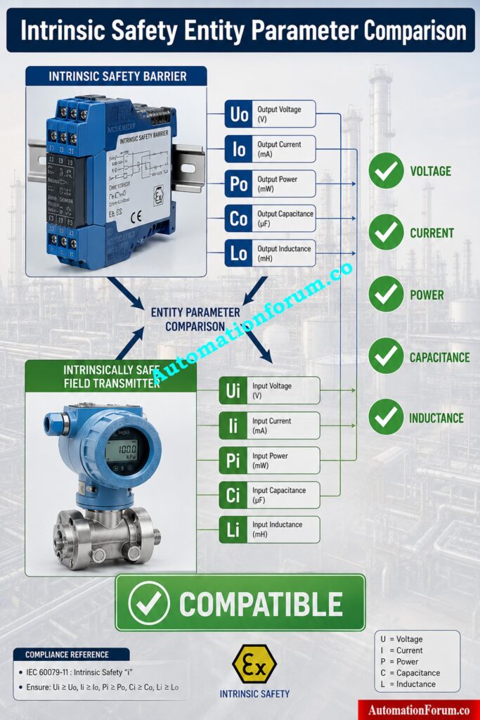
After the calculations, the calculator checks the five entity parameter criteria that are required.
Voltage Compatibility
Uo ≤ Ui
If this condition is violated, the field device could receive more voltage than its certified safe limit.
Current Compatibility
The maximum short circuit current supplied by the associated apparatus must remain below the maximum input current of the field device.
Io ≤ Ii
This ensures that excessive fault current cannot reach the hazardous area equipment.
Power Compatibility
The maximum available output power of the barrier or galvanic isolator must not exceed the certified input power of the field device.
Po ≤ Pi
Power verification is an additional safety check on top of voltage and current.
Capacitance Compatibility
Co ≥ Ci + Cable Capacitance
This comparison failure suggests too much stored electrical energy in the loop.
Inductance Compatibility
The overall inductance of the field device and cable must also be below the external inductance allowed.
Lo ≥ Li + Cable Inductance
This check aims to prevent too much magnetic energy being an ignite source under fault conditions.
Don’t Mix These Cable Types Until You Read This: Difference Between Intrinsically Safe (IS) and Non-IS Cables
Final Compatible or Not Compatible Decision
After all five engineering comparisons are made, the calculator then takes a global look at the results.
A loop is declared Compatible if and only if all entity parameters satisfy their acceptance condition. If one comparison is not satisfied, the entire result is Not Compatible and the engineer has to analyze the parameter that failed before continue with the installation.
Essential Engineering Calculations That Prevent Hazardous Area Design Errors: Intrinsic Safe Calculation for Instrumentation Design Engineers
Practical Intrinsic Safety Calculation Example for a Refinery
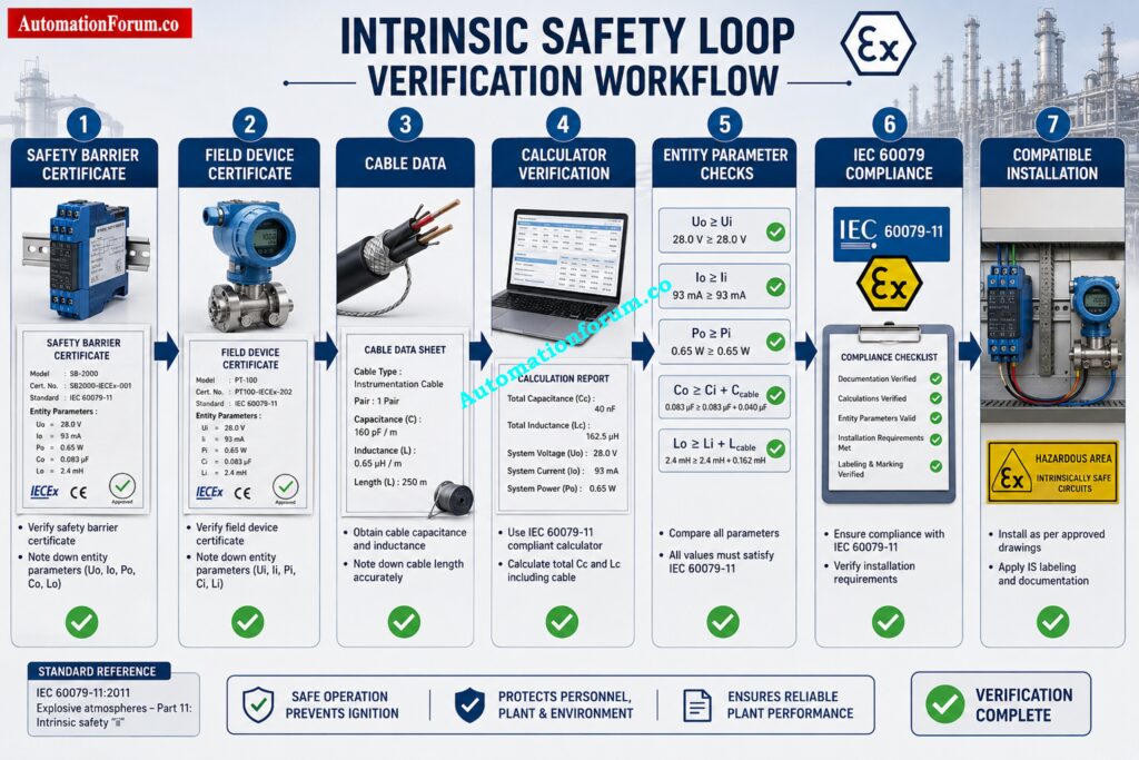
Think about putting an inherently safe pressure transmitter into a galvanic isolator in a Zone 1 process unit at a refinery.
The isolator certificate specifies Uo = 28 V, Io = 93 mA, Po = 0.65 W, Co = 0.083 µF, and Lo = 4.2 mH. The transmitter certificate specifies Ui = 30 V, Ii = 100 mA, Pi = 1.2 W, Ci = 15 nF, and Li = 0.1 mH. The installation uses 300 m of instrumentation cable with 150 pF per meter capacitance and 1 µH per meter inductance.
The calculator first translates everything to common units, then calculates the cable capacitance and inductance, adds those to the transmitter values, and then does the five entity parameter comparisons.
The voltage, current and power checks are all within the limitations needed. The overall capacitance of the transmitter and cable is under the maximum external capacitance allowed. The total inductance of the transmitter and cable is well under the permissible limits.
Since all five verification conditions pass, the calculator reports the barrier and transmitter combination as Compatible.
In an actual refinery project, this result would support the engineering design. However, before final approval, the engineer must still verify the manufacturer control drawing, confirm the gas group, temperature class, equipment protection level, and ensure that the hazardous area classification matches the certified installation requirements.
Never Miss These Critical Installation Checks During Commissioning: Installation Checklist for Intrinsically Safe Instrument (Apparatus)
Intrinsic Safety Loop Design Best Practices
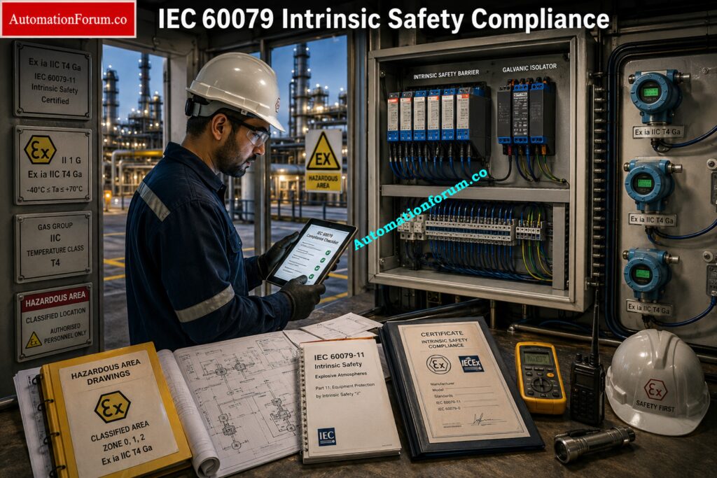
An Intrinsic Safety Entity Parameter Calculator is an excellent engineering tool for verifying entity parameter compatibility, but it should never be the only basis for approving a hazardous area installation. Experienced instrumentation engineers understand that intrinsic safety depends on the complete electrical loop, equipment certification, installation practices, and compliance with applicable standards. The following best practices help ensure that every intrinsically safe loop remains safe throughout its operating life.
Verify Manufacturer Control Drawings
The manufacturer control drawing is the primary engineering document for intrinsic safety verification. It defines approved equipment combinations, wiring methods, grounding requirements, cable limitations, and installation conditions. Even if the calculator indicates that all entity parameters are compatible, the control drawing always takes precedence.
Verify Gas Group Compatibility
Every intrinsically safe barrier and field device must be certified for the same hazardous gas group or for a more severe classification. Installing equipment with mismatched gas group approvals may invalidate the certification even when all electrical parameters satisfy the entity concept.
Verify Temperature Class
The temperature class specifies the maximum surface temperature that equipment can reach during operation. Engineers must verify that the selected transmitter, switch, analyzer, or valve positioner meets the required temperature class for the hazardous area where it will be installed.
Verify Equipment Protection Level
Equipment Protection Level identifies the degree of protection provided by intrinsically safe equipment.
For example, an Ex ia loop provides a higher level of fault tolerance than an Ex ib installation. The selected equipment protection level must satisfy the project hazardous area classification and safety philosophy.
Verify Cable Electrical Characteristics
Cable capacitance and inductance directly influence entity parameter calculations.
Whenever possible, engineers should obtain cable electrical characteristics from the manufacturer’s technical datasheet instead of relying on standard industry assumptions. Cable substitutions during construction should always be reviewed because different cable types may produce different electrical values.
Verify Hazardous Area Classification
Intrinsic safety verification should always be consistent with the approved hazardous area classification drawings.
Before installation, engineers should verify the zone classification, gas group, equipment protection level, ambient temperature limits, and environmental conditions specified for the installation location.
Review Hazardous Area Certification Documents
In addition to entity parameters, equipment certificates are a source of crucial information.
These limits are installation limits, permissible ambient temperature, special conditions of usage, limits of approval and markings on equipment. These documents aid in the prevention of certification issues that are not discoverable through calculations alone.
Never Depend Only on the Calculator
Engineering calculators significantly reduce calculation effort, but they cannot replace engineering judgment.
The final approval of an intrinsically safe loop should always include certificate verification, control drawing review, cable inspection, hazardous area documentation, and compliance with project engineering specifications. The calculator itself also reminds users that it is a design verification aid and not a substitute for certification review.
Most Engineers Confuse These Safety Concepts Until Now: Difference Between Intrinsically Safe and Explosion-Proof
Common Intrinsic Safety Design Mistakes Engineers Should Avoid
Even experienced engineers occasionally make mistakes during intrinsic safety verification. The following issues are among the most frequently encountered during engineering reviews and commissioning activities.
- Using operating voltage instead of certified Uo from the barrier certificate.
- Comparing normal loop current instead of the certified Io and Ii values.
- Ignoring cable capacitance for long field cable installations.
- Forgetting to include cable inductance in total loop calculations.
- Using wrong engineering units without converting value of capacitance or inductance
- Failing to add the capacitance and inductance of multiple field devices connected on the same intrinsically safe loop.
- Approving equipment based only on entity parameters without verifying gas group, temperature class, and equipment protection level.
- Relying only on the calculator while ignoring manufacturer control drawings, certification documents, and project installation requirements.
Avoiding these mistakes greatly improves design quality and reduces commissioning problems.
Applications of the Intrinsic Safety Entity Parameter Calculator
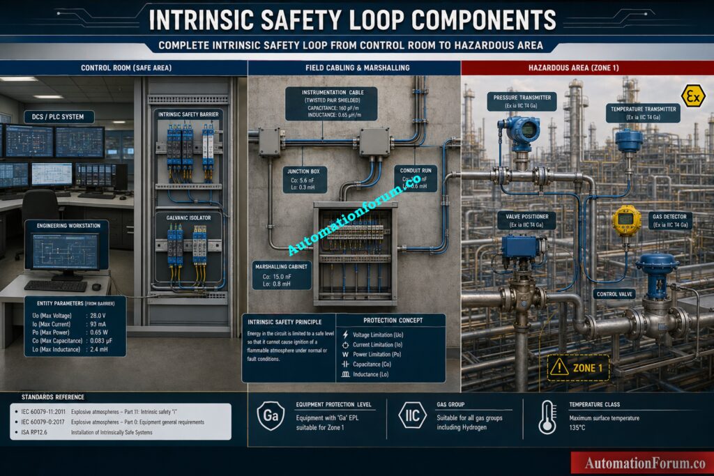
The Intrinsic Safety Entity Parameter Calculator is widely used throughout the process industries wherever intrinsically safe instrumentation circuits are installed.
- In Oil and Gas facilities, engineers verify pressure transmitters, flow transmitters, level instruments, valve positioners, and gas detectors installed in hazardous production areas.
- At Refineries , where the calculator is applied in front end engineering design, detailed engineering, shutdown changes and brownfield expansion projects.
- In Chemical Plants it provides safe loop design for reactors, storage systems, blending units and hazardous process regions handling flammable chemicals.
- In Power Plants it is used by engineers for inherently safe instrumentation linked with fuel handling systems, hydrogen cooled generators and chemical dosing plants.
- Useful for checking instruments around biogas digesters, sludge treatment systems and chemical storage areas in Water Treatment Plants.
- It is used in Pharmaceutical Plants where solvent handling and clean process sections require approved hazardous area instrumentation.
- On Offshore Platforms, the calculator is routinely used for hazardous area instrumentation subjected to long cable runs between field equipment and control rooms.
- In Pipeline Facilities and Tank Farms, it helps engineers verify remote pressure, flow, temperature, and level instrumentation where long field cables make capacitance and inductance calculations especially important.
Learn How Explosion Protection Saves Industrial Facilities Every Day: Exploring Explosion-Proof: Safety in Hazardous Environment
Why Intrinsic Safety Entity Parameter Verification is Essential for Safe Industrial Automation
Intrinsic safety verification is one of the most important responsibilities of an instrumentation engineer working with hazardous area installations. Correctly matching an intrinsic safety barrier or galvanic isolator with a certified field device helps ensure that electrical energy within the loop remains below the level capable of igniting an explosive atmosphere.
An Intrinsic Safety Entity Parameter Calculator simplifies this engineering task by automatically performing unit conversions, calculating cable capacitance and inductance, summing loop reactance, and verifying voltage, current, power, capacitance, and inductance compatibility. This reduces the calculation time, improves consistency and reduces the chances of manual errors in loop design.
Yet successful intrinsic safety design is more than just numerical verification. Always before approving any installation, engineers should review the manufacturer certificates, approved control drawings, hazardous area classification documents, gas group compatibility, temperature class, equipment protection level and project specifications.
Verification of entity parameters, together with good engineering judgment and adherence to applicable standards becomes an essential part of designing safe, reliable and compliant hazardous area instrumentation systems that continue protecting personnel, equipment and plant operations throughout their service life.
Understand the Device That Protects Every Hazardous Instrument Loop: What is a Safety Barrier? & how does Safety Barrier work?
Frequently Asked Questions about Intrinsic Safety Entity Parameters
What is the concept of intrinsic safety entity?
The Entity Concept verifies that the output parameters of an intrinsic safety barrier or galvanic isolator are compatible with the input parameters of the connected field device. It ensures the loop cannot release enough electrical energy to ignite a hazardous atmosphere.
Is IEC 60079 related to intrinsic safety?
Yes. The IEC 60079 series deals with equipment and installations in explosive atmospheres IEC 60079 11 includes the standards for inherently safe equipment IEC 60079 14 addresses the installation methods.
What are the requirements for intrinsically safe systems?
An intrinsically safe loop must be compatible with voltage, current, power, capacitance and inductance. It must also be correctly specified for Gas Group, Temperature Class, Equipment Protection Level and approved control drawings.
What is intrinsic safety calculation?
Intrinsic safety calculation is the engineering process of verifying that the barrier, field device, and cable parameters meet the Entity Concept requirements and comply with applicable hazardous area standards.
Is a 4 to 20 mA loop intrinsically safe?
Not automatically. A standard 4 to 20 mA loop becomes intrinsically safe only when it uses certified intrinsically safe equipment, an approved barrier or galvanic isolator, and satisfies all entity parameter requirements.
What are the levels of intrinsic safety?
Intrinsic safety protection levels include Ex ia, Ex ib, and Ex ic. Ex ia provides the highest level of protection, while Ex ib and Ex ic are intended for applications with progressively lower fault tolerance requirements.
Why is cable capacitance and inductance important in intrinsic safety?
Instrumentation cables contain electrical energy which adds to the overall loop capacitance and inductance. These values must remain within the barrier’s allowable Co and Lo limits to maintain intrinsic safety.
What is the difference between a Zener Barrier and a Galvanic Isolator?
A Zener Barrier requires a high integrity earth connection to limit energy, but a Galvanic Isolator provides electrical isolation and often does not require a separate intrinsic safety earth, making installation simpler.
Can multiple field devices be connected to one intrinsically safe loop?
Yes, but only if the combined capacitance, inductance, voltage, current, and power of all connected devices remain within the certified limits of the associated apparatus and comply with the control drawing.
Can an Intrinsic Safety Entity Parameter Calculator replace manufacturer control drawings?
No. An Intrinsic Safety Entity Parameter Calculator is an engineering verification tool that simplifies calculations, but final approval must always be based on manufacturer certificates, approved control drawings, and applicable hazardous area standards.
Refer the below link for the Why Choose Intrinsic Safety (IS) for Hazardous Area Instrumentation?
