
- Thermocouple Color Code and EMF Calculator for Instrumentation Engineers
- What Is a Thermocouple Color Code and EMF Calculator?
- Why Thermocouple Wire Color and Polarity Matter
- How to Use the Thermocouple EMF Calculator
- Thermocouple EMF Calculation Formula
- Type K Thermocouple EMF Calculation Example
- How to Interpret Thermocouple EMF Calculator Results
- Industrial Applications of Thermocouple Color and EMF Calculation
- Common Thermocouple Measurement Mistakes
- Frequently Asked Questions About Thermocouple Color Codes and EMF
- Engineering Recommendations for Accurate Thermocouple EMF Calculation
Thermocouple Color Code and EMF Calculator
Thermocouple Wire Identification
NIST ITS 90 EMF Screening Calculator
Thermocouple Calculation Results
Calculation Steps
| Parameter | Calculated Value |
|---|
Thermocouple Color Reference
| Type | Common Alloy Pair | Typical Application |
|---|---|---|
| K | Chromel / Alumel | General purpose, oxidizing environments |
| J | Iron / Constantan | General industrial service; protect iron from oxidation |
| T | Copper / Constantan | Low temperature and cryogenic applications |
| E | Chromel / Constantan | High output sensitivity |
| N | Nicrosil / Nisil | High temperature stability |
| R | Platinum Rhodium / Platinum | High temperature laboratory and process use |
| S | Platinum Rhodium / Platinum | High temperature reference and process use |
| B | Platinum Rhodium / Platinum Rhodium | Very high temperature applications |
Engineering Theory
Why Cold Junction Compensation Matters
A thermocouple generates a small voltage related to the temperature difference between its measuring junction and reference junction. The instrument measures the terminal temperature and compensates for the reference junction contribution to determine process temperature.
Installation Checks
- Confirm thermocouple type and extension cable grade.
- Check positive and negative polarity at the sensor head and instrument terminals.
- Avoid ordinary copper extension wire unless a suitable conversion arrangement is designed.
- Route thermocouple wiring away from VFD output cables and other electrical noise sources.
- Ground shields according to the project grounding philosophy and instrument manufacturer guidance.
Thermocouple Color Code and EMF Calculator for Instrumentation Engineers
Thermocouple Color Code and EMF Calculator Instrumentation engineers need to identify thermocouple wire colors, check the polarity of conductors and calculate the millivolt output of different thermocouple kinds. It supports Types K, J, T, E, N, R, S and B with IEC 60584 3 and ANSI MC96.1 convention color references.
In industrial plants, incorrect thermocouple wiring, reversed polarity, and improper reference junction compensation can lead to incorrect temperature readings. This calculator provides a convenient reference during instrumentation design, installation, commissioning, calibration checks, and troubleshooting.
Simulate Temperature Sensors Accurately Before Starting Loop Commissioning: How to simulate RTDs and Thermocouples using Multifunction calibrator?
What Is a Thermocouple Color Code and EMF Calculator?
A thermocouple produces a small electrical voltage when its measuring junction and reference junction are at different temperatures. The instrument measures this voltage and converts it into a temperature value using the selected thermocouple characteristics.
The calculator combines two useful functions. The first identifies the positive conductor, negative conductor, and cable jacket color for the selected thermocouple type and color standard. The second estimates the thermoelectric voltage associated with the entered process and reference junction temperatures.
The tool supports eight common thermocouple types.
| Thermocouple type | Common alloy combination | Typical application |
| Type K | Chromel and Alumel | General industrial temperature measurement |
| Type J | Iron and Constantan | General industrial service |
| Type T | Copper and Constantan | Low temperature applications |
| Type E | Chromel and Constantan | Applications requiring higher EMF output |
| Type N | Nicrosil and Nisil | High temperature measurement |
| Type R | Platinum rhodium and platinum | High temperature process measurement |
| Type S | Platinum rhodium and platinum | Laboratory and industrial reference measurement |
| Type B | Platinum rhodium alloys | Very high temperature applications |
The appropriate thermocouple depends on the process temperature, atmosphere, sensor construction, measurement requirements, and applicable project specifications.
Refer the below link for the Thermocouple Voltage ↔ Temperature Calculator
Why Thermocouple Wire Color and Polarity Matter

Thermocouple extension cables use specific conductor materials and identification systems. Correct identification helps prevent wiring errors during installation, junction box termination, panel wiring, and instrument replacement.
Prevent Commissioning Delays With This Essential Thermocouple Checklist: Thermocouple Commissioning Checklist
The calculator provides two color reference options.
- Under the IEC color convention represented by the calculator, the negative conductor is white. The positive conductor and outer jacket use the identifying color associated with the thermocouple type.
- Under the ANSI color convention represented by the calculator, the negative conductor is red. The positive conductor and outer jacket colors depend on the selected type.
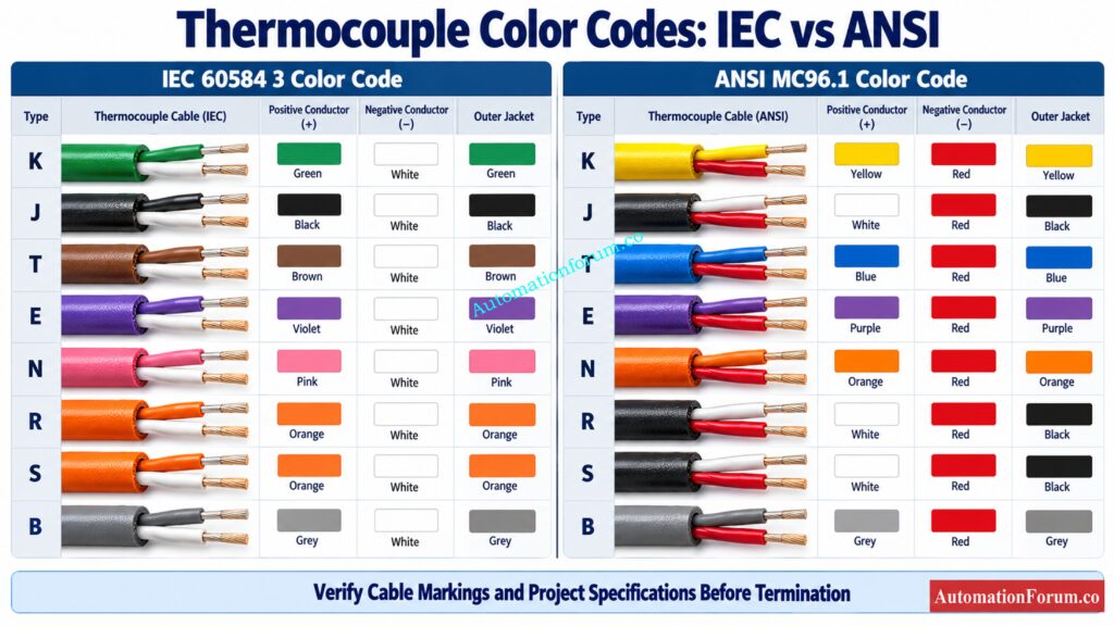
For example, the calculator displays a green positive conductor and white negative conductor for Type K under its IEC selection. Under its ANSI selection, Type K uses yellow for positive and red for negative.
Color conventions can vary according to the applicable standard, cable construction, manufacturer, and installation requirements. Always verify the cable markings and project specifications before making a termination. Never identify an unknown thermocouple solely by its insulation color.
Fix Incorrect Temperature Readings After Replacing Your Thermocouple Sensor: Troubleshooting Procedure Thermocouple Reading Wrong Temperature After Replacement
How to Use the Thermocouple EMF Calculator

The calculator requires a thermocouple type, a color standard, a process temperature, and a reference junction temperature.
Step 1: Select the thermocouple type
Choose type K, J, T, E, N, R, S or B according to the configuration of the sensor and transmitter installed. Each thermocouple has various voltage vs temperature characteristics and the suitable type must be selected.
Improve Measurement Accuracy With Proper Transmitter Calibration Techniques: How to calibrate Thermocouple Transmitter?
Step 2: Select the color standard
International color reference: IEC 60584 3 North American color reference: ANSI MC96.1 Refer to the real cable documentation for the colors to use when terminating fields.
Step 3: Enter the process temperature
Enter the temperature of the measuring junction (in °C). This is the hot junction temperature the calculator uses.
Step 4: Enter the reference junction temperature
Follow These Eight Calibration Steps For Reliable Temperature Measurements: 8 Steps Calibration Procedure for Thermocouple
Step 5: Calculate the EMF
Choose Calculate EMF. The calculator shows the estimated compensated EMF, hot junction EMF, reference junction EMF, average sensitivity, and the steps of the computation.
Master Safe Thermocouple Replacement With This Proven Field Procedure: Faulty Thermocouple Replacement Procedure in Process Area: Complete Step-by-Step Field Guide for Instrumentation Engineers
Thermocouple EMF Calculation Formula

The calculator uses the following relationship to predict the thermocouple EMF:
Compensated EMF = E(Thot) − E(Tref)
Where:
- E(Thot) is the thermoelectric voltage predicted at the process temperature.
- E(Tref) is the thermoelectric voltage at the reference junction temperature.
- Thot is the temperature of the process in °C.
- Tref is the reference junction temperature in degrees Celsius.
The calculator uses representative temperature and EMF reference points with linear interpolation between adjacent points. This method provides a quick estimate, but it is not equivalent to evaluating the complete official NIST ITS 90 reference functions.
Average sensitivity is calculated as:
Average sensitivity = [E(Thot) − E(Tref)] ÷ (Thot − Tref)
The result is expressed in microvolts per degree Celsius. Sensitivity is not calculated when the temperature difference is zero.
Avoid Costly Wiring Mistakes With These Thermocouple Cable Selection Rules: Thermocouple Wire vs. Thermocouple Extension Wire: The Complete Guide for Instrumentation Engineers
Type K Thermocouple EMF Calculation Example
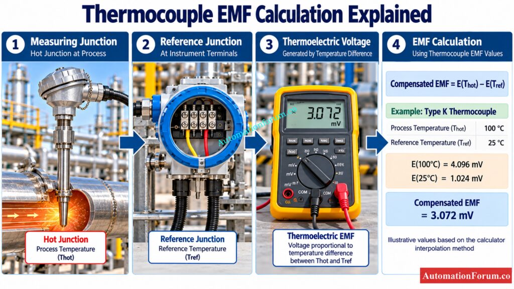
Consider a Type K thermocouple connected to a temperature transmitter in an industrial process.
- Process temperature = 100°C
- Reference junction temperature = 25°C
From the representative values used by the calculator, the estimated Type K EMF at 100°C is 4.096 mV.
At 25°C, linear interpolation between the 0°C and 100°C reference points gives an estimated EMF of 1.024 mV.
Therefore:
- Compensated EMF = 4.096 − 1.024
- Estimated compensated EMF = 3.072 mV
- The temperature difference is 75°C.
- Average sensitivity = 3.072 ÷ 75 × 1000
- Average sensitivity = 40.96 µV/°C
These values illustrate the calculator’s implemented interpolation method. They are estimates rather than certified calibration values.
How to Interpret Thermocouple EMF Calculator Results
The calculator provides several results that help engineers understand the voltage calculation.
- Hot junction EMF: The calculated voltage associated with the process temperature relative to the reference temperature used by the thermocouple reference function.
- Reference junction EMF: The emf determined from the temperature of the reference junction.
- Compensated EMF: Difference between two estimated voltage values. This is the thermocouple voltage equivalent to the temperature differential in the calculator sign convention.
- Average sensitivity: The average change in EMF per degree Celsius over the temperature range you specified.
- Calculation steps: The tool shows the selected type, the two EMF estimates, the subtraction, and calculation of average sensitivity.
A positive or negative EMF result indicates the direction of the calculated voltage according to the selected temperature difference. A negative result does not automatically indicate a faulty thermocouple.
Discover Reliable Field Tests To Identify Faulty Thermocouple Sensors: Testing a Thermocouple With a Multimeter: A Complete Field Guide for Instrumentation Engineers
Industrial Applications of Thermocouple Color and EMF Calculation
Thermocouple Color Codes for Instrumentation Design and EPC Projects
Engineers can use the color reference when preparing instrument installation details, cable schedules, termination drawings, and field wiring documentation. The selected cable type and identification system must agree with project specifications.
Follow Eight Essential RTD Calibration Steps For Better Accuracy: RTD Calibration Procedure: 8 Steps for Accurate Calibration
Thermocouple EMF Calculation for Commissioning and Loop Checking
In commissioning, engineers can validate the predicted polarity and estimate the millivolt signal for a known temperature state. The results can help to troubleshoot when inspecting the thermocouple, extension cable, transmitter and control system configuration.
Detect Common RTD Failures Early And Prevent Unexpected Shutdowns: Common Reasons for RTD Failures and How to Prevent Them
Thermocouple Polarity Checks for Maintenance and Troubleshooting
If you get a temperature reading that is not correct, you can check the polarity of the leads and the predicted EMF to see if there are any wiring errors or if the type of thermocouple is set incorrectly. Further examinations may be required to evaluate sensor damage, bad connections, electrical interference or reference junction compensation issues.
Choose The Right Temperature Sensor Before Finalizing Your Design: Choosing Between Thermocouples and RTDs: A Practical Guide for Temperature Sensing
Thermocouple EMF Calculation for Calibration Support
It can be used to show the relationship between temperature and thermocouple voltage during training and preliminary tests. Calibration shall be carried out using adequate reference equipment and verified conversion procedures.
Eliminate Temperature Errors By Understanding Reference Junction Compensation: Why Thermocouple Reference Junction Compensation(CJC) is Essential for Accurate Temperature Measurement ?
Common Thermocouple Measurement Mistakes
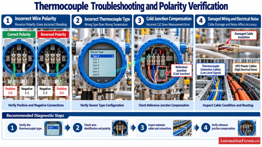
- Using the wrong thermocouple type: A transmitter configured for Type K will not correctly interpret every other thermocouple type.
- Reversing conductor polarity: Incorrect polarity can produce an unexpected or reversed temperature response.
- Using ordinary copper wire as an extension: The use of copper wiring may bring additional thermoelectric effects at junctions of various metals due to inappropriate connections. Use the proper extension or compensating cable.
- Ignoring cold junction compensation: The voltage measured at the instrument terminals is dependent on the temperatures of both junctions. Measurement mistake might occur due to wrong reference temperature adjustment.
- Ignoring electrical noise: Thermocouple wires should not be run near variable frequency drive output cables and other major sources of noise. De-energize shields in accordance with the project grounding concept and the instructions of the instrument manufacturer
- Relying on approximate values for critical measurements: Linear interpolation between representative points is suitable for screening and learning, but it does not replace validated thermocouple conversion functions.
Convert Millivolt Signals Into Accurate Process Temperature Values Quickly: How to Convert Thermocouple Millivolts to Temperature: A Step-by-Step Guide
Frequently Asked Questions About Thermocouple Color Codes and EMF
What color is a J thermocouple?
Under the ANSI color code, Type J thermocouples use white as the positive conductor and red as the negative conductor. Under the IEC standard, the positive conductor is black and the negative conductor is white.
What color is a Type E thermocouple?
Under the ANSI color code, Type E thermocouples use purple as the positive conductor and red as the negative conductor. Under the IEC standard, the positive conductor is violet and the negative conductor is white.
Understand RTD Placement Around Orifice Plates Before Installation: Why RTD Temperature Sensors are Installed Downstream of Orifice Plates?
Is red positive or negative on a thermocouple?
Under the ANSI color code, red generally indicates the negative conductor for common thermocouple types. Refer to the appropriate color standard, as wire colors will vary by region and cable specification.
How is EMF generated in thermocouples?
If the measurement junction and the reference junction are at different temperatures, the two dissimilar metals generate thermocouple EMF due to the Seebeck effect. The resulting millivoltage is used to calculate the measured temperature.
Identify RTD Faults Faster With These Practical Testing Methods: RTD Testing Methods
What are the color codes for thermocouples?
The colors of thermocouples are determined by the type of sensor and the standards, such as ANSI or IEC. Always check the cable markings and the manufacturer documentation before making electrical connections.
What is a thermocouple EMF calculator?
Thermocouple EMF calculator Thermocouple emf calculator calculates the emf generated by a chosen thermocouple at given temperatures. It can provide wire color references and a rough average sensitivity for engineering calculations.
Complete RTD Commissioning Checks Before Handing Over Your Plant: RTD Commissioning Checklist
How do I identify Type K thermocouple wires?
Select Type K and the corresponding color standard in the calculator to verify the expected conductor colors. Before connecting wires to a transmitter or input module, verify the marks on the cable and the product documentation.
What is cold junction compensation in a thermocouple?
Cold connection compensation cancels out the temperature at the point where the thermocouple is connected to the measurement device. This enables the instrument to correctly read the voltage obtained and calculate the temperature of the process.
Verify PT100 Sensor Accuracy Before Accepting Critical Measurements: RTD Tolerance Calculator for Accurate Temperature Measurement
Why does thermocouple polarity matter?
The polarity of a thermocouple is the direction of the voltage it generates relative to the measuring equipment. Incorrect temperature measurements or an unexpected response to a change in process temperature may result from reversed wiring.
Why can a thermocouple show an incorrect temperature?
Typical causes are reversed polarity, improper sensor type configured, bad extension wire, electrical noise, or cold junction compensation issues. Verify the sensor wiring, configuration and reference junction conditions before changing the instrument settings.
Compare Practical Conversion Methods Before Interpreting Thermocouple Signals: Converting Thermocouple Millivolts to Temperature: Methods and Examples
Engineering Recommendations for Accurate Thermocouple EMF Calculation
The Thermocouple Color Code and EMF Calculator is a useful reference to use for instrumentation design, installation, commissioning, and preliminary troubleshooting. Verify the type of thermocouple used, the cable identification, the polarity and the reference junction temperature before interpreting the data.
Refer the below link for the RTD Callendar–Van Dusen Calculator | Accurate PT100, PT500, and PT1000 Conversion
