- Displacer Level Transmitter Calibration Calculator Complete Guide
- Displacer Level Transmitter Dry Calibration Weight Calculator
- What is a Displacer Type Level Transmitter?
- What is Dry Calibration of Displacer Level Transmitter?
- What is Displacer Level Transmitter Calibration Weight Calculator
- Displacer Level Transmitter Calculator Input Parameters
- How to Use the Displacer Calibration Calculator Step by Step
- Displacer Calibration Calculator Output Results
- Displacer Level Transmitter Calibration Formula Explained
- Displacer Calibration Example Calculation Step by Step
- Where is Displacer Level Transmitter Calibration Used
- Who Should Use This Displacer Calibration Calculator
- When to Use Displacer Level Transmitter Calibration Calculator
- Benefits of Displacer Calibration Weight Calculator
- Common Mistakes in Displacer Level Transmitter Calibration
- Best Practices for Accurate Displacer Calibration
- Displacer Level Transmitter Dry Calibration and Calculation FAQ
- Displacer Level Transmitter Calibration Calculator Summary
Displacer Level Transmitter Calibration Calculator Complete Guide
A displacer type interface level transmitter dry calibration weight calculator is one of the most practical tools for instrumentation engineers who work with separators, vessels, and two phase level measurement systems. The attached calculator is built to estimate zero calibration weight, span calibration weight, displacer volume, actual span, and linearity check weights from the displacer geometry and the specific gravity values of the two liquids involved. It is designed exactly for offline testing and calibration planning where no process fluid is available.
Dry Calibration of Displacer Level Transmitter Explained for Engineers
This article explains the working principle, the formulas behind the calculator, the meaning of each input, and the field use of dry calibration of displacer transmitter in a clear engineering format. It is written for instrumentation professionals, EPC engineers, commissioning teams, and control engineers who need a reliable reference before carrying out displacer level transmitter calibration. The calculator uses a cylindrical displacer model and calculates the calibration weights from the buoyancy difference between the lighter and heavier liquid phases.
Displacer level transmitter calibration is performed by calculating buoyancy based weight loss using displacer volume and liquid specific gravity.
Crack Advanced Interface Leveltrol Troubleshooting Quiz: Advanced Interface Leveltrol Troubleshooting Quiz
Displacer Level Transmitter Dry Calibration Weight Calculator
Displacer Type Interface Level Transmitter
Dry Calibration Weight Calculator
Calculate zero & span calibration weights and linearity check weights for displacer-type interface level transmitters — no process fluid required.
| % of Span | Calibration Weight (g) | Step Value (g per 25%) |
|---|
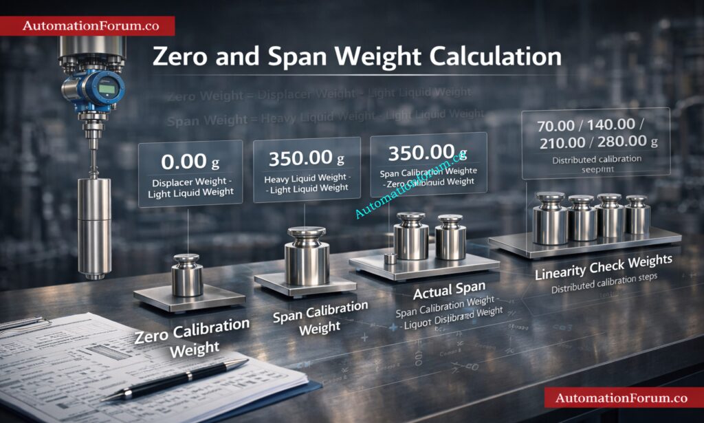
How It Works — Formulas & Methodology
Step 1 — Displacer Volume (Cylindrical Formula)
The displacer is modelled as a solid cylinder. Volume is calculated as:
where D = displacer diameter (cm), L = displacer length (cm). Result in cm³.
Step 2 — Zero Calibration Weight (0%)
When the displacer is fully submerged in the lighter (upper) liquid, the apparent weight is reduced by the buoyant force:
This is the calibration weight hung on the displacer rod to simulate 0% interface level.
Step 3 — Span Calibration Weight (100%)
When the displacer is fully submerged in the heavier (lower) liquid, the buoyant force is greater, reducing apparent weight further:
W_span < W_zero because the heavier liquid exerts more buoyancy. The displacer actual weight W must be greater than V × SG_heavy.
Step 4 — Actual Span & Linearity Check Weights
The actual span is the buoyancy difference between the two liquids:
As the interface rises, heavier liquid displaces lighter liquid → more buoyancy → lower apparent (calibration) weight.
About This Interface Level Transmitter Calibration Calculator
This displacer type interface level transmitter dry calibration weight calculator helps instrumentation engineers, control system technicians, and process automation professionals determine the precise test weights required to simulate the buoyancy conditions experienced by a displacer — without needing process fluid in the vessel.
In a displacer-type level transmitter, the displacer is a solid cylindrical float that experiences an upward buoyant force proportional to the specific gravity of the liquid it is submerged in. During dry calibration, calibration weights are hung on the displacer rod to replicate this buoyancy force, allowing engineers to set zero and span of the transmitter offline.
This tool supports interface level applications (two-liquid-phase systems, such as hydrocarbon-water interfaces in separators) and single-fluid level applications. Enter the displacer geometry and liquid specific gravities to instantly obtain the zero calibration weight, span calibration weight, and linearity check weights at 25%, 50%, 75%, and 100% of span.
What is a Displacer Type Level Transmitter?
Working Principle of Displacer Level Transmitter Based on Buoyancy
A displacer type level transmitter is a buoyancy based level instrument used to measure liquid level or interface level in process vessels. It works on Archimedes principle. When the displacer is immersed in liquid, the liquid pushes it upward with a buoyant force equal to the weight of the liquid displaced. Because of this force, the apparent weight of the displacer becomes lower than its actual weight. That change in apparent weight is converted into a level signal by the transmitter mechanism. The calculator attached to page is based on this exact buoyancy principle.
Archimedes Principle in Level Measurement
In simple field terms, as the liquid level rises, more of the displacer is surrounded by liquid, so the buoyant force increases. When the buoyant force increases, the effective hanging weight becomes lower. In interface service, the same displacer sees two different liquid phases, usually a lighter upper liquid and a heavier lower liquid. The difference in buoyancy between those two liquids is what makes interface measurement possible. That is why accurate displacer weight calculation is essential for proper calibration.
Master Interface Level Measurement Selection Procedure: Interface Level Measurement Selection Procedure – Complete 2025 Guide for Process Engineers
What is Dry Calibration of Displacer Level Transmitter?
Why Dry Calibration is Used in Industrial Applications
Dry calibration is the process of simulating the operating buoyancy condition of a displacer without using the real process liquid. Instead of placing the transmitter in a vessel, calibration weights are applied to the displacer rod or mechanism to imitate the apparent weight that the instrument would see in service. This calculator clearly follows this method by computing theoretical calibration weights from weight, diameter, length, and specific gravity inputs.
Advantages of Dry Calibration Without Process Fluid
This method is widely used during shop testing, pre commissioning, turnaround maintenance, and hazardous area work where live fluid testing is not practical or safe. Dry calibration is especially useful in oil and gas, refineries, chemical plants, and water treatment systems. It gives instrumentation teams a fast and repeatable way to verify zero and span settings before the instrument is put online.
Difference Between Dry Calibration and Wet Calibration
The main difference between wet calibration and dry calibration is the presence of process fluid. Wet calibration uses actual liquid and real buoyancy conditions. Dry calibration uses calculated weights to simulate that buoyancy. The attached calculator is made for the dry method, and it even includes a warning note that the results are theoretical and should always be checked against the manufacturer data sheet and site corrections.
Unlock Displacer Interface Calibration Weight Calculator: Displacer type interface level transmitter dry calibration weight calculator
What is Displacer Level Transmitter Calibration Weight Calculator
Why Use a Displacer Calibration Calculator
A displacer calibration weight calculator is an instrumentation calibration calculator that helps determine the exact weights needed to simulate level conditions for a displacer transmitter. The calculator on this page is specifically designed for a displacer type interface level transmitter dry calibration weight calculator. It outputs the displacer volume, zero calibration weight, span calibration weight, actual span, and linearity check weights for 25 percent, 50 percent, 75 percent, and 100 percent span.
Importance of Accurate Weight Calculation in Calibration
This tool solves a common field problem. Manual calculations can be slow and can easily lead to mistakes when converting dimensions, checking buoyancy, or applying specific gravity values. A small error in SG or volume can produce the wrong test weight and distort the calibration. For that reason, a calculator like this saves time, improves confidence, and reduces the chance of calibration drift or false zero setting.
Instant DP Interface Level Calculator: Interface level calculator from Differential pressure (DP)
Displacer Level Transmitter Calculator Input Parameters
The attached calculator asks for five main inputs. Each one matters because the output depends on the real geometry of the displacer and the density of the liquids involved. The file shows the exact input fields for displacer weight, diameter, length, lighter liquid specific gravity, and heavier liquid specific gravity.
Displacer Weight Calculation Input
This is the actual physical weight of the displacer in grams. The calculator uses this value as the starting point and then subtracts the buoyant force created by the liquid. In field practice, the weight must be greater than the buoyancy created by the heavier liquid, otherwise the calculated calibration weight may become invalid. The attached calculator even includes an input validation warning for this condition.
Displacer Diameter and Volume Calculation
The diameter is required to calculate the cylindrical volume of the displacer. The calculator models the displacer as a solid cylinder, which is a standard and practical approach for many industrial displacer assemblies. The volume is computed from diameter and length, then used to estimate buoyancy.
Displacer Length and Its Effect on Buoyancy
The length is the axial length of the displacer body. Together with diameter, it defines the total displaced volume. A longer displacer creates a larger buoyant force, so length has a direct effect on the zero and span calibration weights.
Explore Submersible Level Transmitter Benefits: Submersible Level Transmitters: Applications, Working Principles, and Benefits
Specific Gravity of Light Liquid in Interface Measurement
This is the SG of the upper phase in an interface application. In many process vessels, this may be crude oil, condensate, naphtha, or another lighter hydrocarbon. The calculator uses this value to compute the buoyant force at the lower buoyancy condition. The file uses examples such as crude oil, diesel, and naphtha, which are common lighter phase references.
Specific Gravity of Heavy Liquid in Interface Calibration
This is the SG of the lower phase, such as water, brine, or MEG solution. In interface service, this value is normally higher than the upper phase SG. The attached calculator requires the heavy liquid SG to be greater than the light liquid SG, because the span is based on the difference in buoyancy between the two liquids.
Crack Varying Tank DP Interface Calculation: DP calculator for Interface level measurement – Transmitter installed with Varying Tank Level and two Bubble Tubes
How to Use the Displacer Calibration Calculator Step by Step
Using the calculator is straightforward for a field engineer.
Step 1 Enter Displacer Weight
Enter the actual displacer weight in grams.
Step 2 Enter Diameter and Length
Enter the displacer diameter and length in centimeters.
Step 3 Enter Light Liquid Specific Gravity
Enter the specific gravity of the lighter liquid.
Step 4 Enter Heavy Liquid Specific Gravity
Enter the specific gravity of the heavier liquid.
Step 5 Calculate Calibration Weights
Click calculate to generate the results.
Step 6 Analyze Output Results
Read the displacer volume, zero calibration weight, span calibration weight, and actual span.
Step 7 Verify Linearity Check Values
Use the linearity table to check calibration weights at 25 percent increments across the span.
This workflow matches the actual interface of this calculator, which was built to help engineers calculate dry calibration weights without process fluid.
Master Bubbler Interface Level DP Calculator: DP calculator for bubbler method Interface level measurement – Transmitter installed with Constant Tank Level and single Bubble Tube
Displacer Calibration Calculator Output Results
The output section of the calculator is very useful because it translates the entered physical data into actionable calibration values. The file shows four main result cards and a linearity table below them.
Displacer Volume Calculation Explained
This is the cylindrical volume of the displacer in cubic centimeters. It tells you how much liquid the displacer displaces when fully immersed. Since buoyancy depends on displaced volume, this number is central to the whole calculation.
Zero Calibration Weight Calculation
This is the calibration weight that simulates the displacer in the lighter liquid condition. It is the starting point for the level setting and represents the apparent weight at the zero point of calibration.
Span Calibration Weight Calculation
This is the calibration weight that simulates the displacer in the heavier liquid condition. Because the heavier liquid creates more buoyancy, the apparent weight becomes lower than the zero calibration condition.
Actual Span Calculation in Interface Level
Linearity Check Weights for 25 50 75 100 Percent
The calculator also generates weights at 25 percent, 50 percent, 75 percent, and 100 percent span. This helps the technician verify that the transmitter response is smooth across the operating range and not only at zero and span. The file explicitly includes this linearly stepped output table.
Crack Constant Level Bubbler Calculation Now: Bubble method Interface level measurement calculation with Constant Tank Level and single Bubble Tube
Displacer Level Transmitter Calibration Formula Explained
The attached calculator uses a very practical calculation path. First it computes volume. Then it calculates buoyancy at the light liquid and heavy liquid conditions. Finally it converts that buoyancy into calibration weights.
Volume Calculation Formula for Displacer
The displacer is treated as a cylinder.
V = π × (D divided by 2) squared × L
Here D is the diameter and L is the length. This gives the displaced volume in cubic centimeters.
Refer the below link for the Calibration Procedures for Level Measurement Devices
Buoyancy Formula Based on Specific Gravity
Buoyancy depends on liquid density and displaced volume. That is the reason specific gravity matters so much in displacer level transmitter calibration. The more dense the liquid, the greater the buoyant force. In interface service, a heavy liquid pushes up harder than a light liquid for the same immersed volume.
Zero Calibration Weight Formula
Zero calibration weight = actual displacer weight minus buoyancy of the light liquid
In the calculator this is shown as W minus V times SG light. This represents the simulated weight when the displacer is in the lighter phase.
Span Calibration Weight Formula
Span calibration weight = actual displacer weight minus buoyancy of the heavy liquid
In the calculator this is shown as W minus V times SG heavy. Since the heavy liquid has higher density, the span weight will be lower than the zero weight.
Actual Span Formula for Interface Measurement
Actual span = V times SG heavy minus V times SG light
This is the buoyancy difference between the two phases. The calculator also divides this by four to produce the 25 percent step value for the linearity table.
Master DP Interface Level Calculator: DP calculator for Interface level measurement
Displacer Calibration Example Calculation Step by Step
Given Data for Industrial Example
Let us use the same sample values shown in the attached calculator.
Displacer weight = 2400 g
Diameter = 7 cm
Length = 32.42 cm
SG light = 0.7
SG heavy = 1.0
Volume Calculation Example
First calculate the volume.
Radius = 7 divided by 2 = 3.5 cm
Volume = 3.1416 × 3.5 × 3.5 × 32.42
Volume = approximately 1248.18 cm³
Zero Weight Calculation Example
Now calculate buoyancy in the lighter liquid.
Light buoyancy = 1248.18 × 0.7 = 873.73 g
Zero calibration weight = 2400 minus 873.73 = 1526.27 g
Span Weight Calculation Example
Now calculate buoyancy in the heavier liquid.
Heavy buoyancy = 1248.18 × 1.0 = 1248.18 g
Span calibration weight = 2400 minus 1248.18 = 1151.82 g
Unlock EPC Level Transmitter Selection Checklist: Level Transmitter Selection Checklist for EPC Engineers – Step-by-Step Guide
Linearity Table Calculation Example
Actual span = 1248.18 minus 873.73 = 374.45 g
25 percent step = 374.45 divided by 4 = 93.61 g
So the linearity check weights become approximately:
25 percent = 1432.66 g
50 percent = 1339.05 g
75 percent = 1245.44 g
100 percent = 1151.82 g
This example shows how the calculator turns physical dimensions and SG values into practical calibration values for field use. The same calculation flow is embedded in the the dry weight calculation tool.
Unlock Remote Seal DP Level Calculation:Interface level measurement using DP transmitter (Remote sealed)
Where is Displacer Level Transmitter Calibration Used
This tool is useful in many industries where interface level measurement matters.
- In oil and gas, it is used for separator vessels, crude oil water interface, and production skids.
- In refineries, it is used for hydrocarbon and water separation services.
- In chemical plants, it helps with liquid interface systems and process vessels carrying different density fluids.
- In power plants, it can be used in condensate and auxiliary systems.
- In water treatment, it helps with tanks and density based level services where buoyancy instruments are used.
- The calculator is suitable wherever displacer type interface level transmitter calibration is required and a dry estimation is preferred before actual installation.
Explore Interface Level Measurement Techniques: Interface level measurement techniques
Who Should Use This Displacer Calibration Calculator
- This calculator is designed for instrumentation engineers, calibration technicians, EPC engineers, commissioning engineers, and DCS or PLC engineers who need a fast and dependable way to estimate displacer weight calculation values before field calibration.
- It is especially helpful for people who handle process level measurement tools and need a practical reference during startup or maintenance.
Master Displacer Level Transmitter Calibration :How to calibrate displacer type level transmitter – Interface liquid application
When to Use Displacer Level Transmitter Calibration Calculator
- Use this calculator during commissioning when the transmitter is being prepared for startup.
- Use it during shutdown maintenance when the instrument is removed and tested offline.
- Use it in factory calibration when you want to verify the response before dispatch.
- Use it in troubleshooting when the output seems incorrect and you need to confirm the expected zero and span calibration weight values.
Benefits of Displacer Calibration Weight Calculator
This calculator saves time because the weights are produced instantly.
- It reduces manual calculation error.
- It improves calibration accuracy.
- It works without process fluid.
- It is useful in hazardous areas where wet testing may not be practical.
- It gives a clear linearity view across the full span.
- It supports faster decision making for field engineers and commissioning teams. The calculator structure on this page is intentionally built around these practical benefits.
Crack Level Troll Dry Calibration Weight: Dry Calibration of Displacer Level Troll Using Weight Loss Calculator
Common Mistakes in Displacer Level Transmitter Calibration
- One common mistake is entering the wrong specific gravity values. A small SG error can change the buoyancy result significantly.
- Another mistake is using incorrect displacer dimensions. If the diameter or length is wrong, the calculated volume will also be wrong.
- A third mistake is ignoring density variation between actual process conditions and assumed calibration conditions.
- A fourth mistake is applying improper simulation weights without checking whether the displacer actual weight is sufficient to overcome buoyancy in the heavy liquid case.
- The calculator guards against this by warning when the calculated buoyancy exceeds the displacer weight.
Master Hybrid Level Measurement Selection Procedure: Hybrid Level Measurement Selection Procedure for EPC Instrumentation Engineers
Best Practices for Accurate Displacer Calibration
- Always verify specific gravity from a laboratory result, process data sheet, or known operating condition.
- Always check the manufacturer data sheet for the transmitter and displacer assembly.
- Always confirm that the displacer weight is greater than the buoyant force created by the heavy liquid.
- Always use calibrated weights when simulating the zero and span conditions.
- Always document the final zero calibration weight and span calibration weight for future maintenance reference.
- These practices help make dry calibration of displacer transmitter more dependable in the field.
Master Wet Leg DP Level Calculation: Wet-Leg Level Calculation for DP Transmitters: Complete Guide for Instrumentation Design
Displacer Level Transmitter Dry Calibration and Calculation FAQ
What is dry calibration of level transmitter?
Dry calibration is the offline simulation of process buoyancy using calculated weights instead of actual liquid.
How do you calculate displacer weight?
You calculate the displacer volume from its diameter and length, then subtract the buoyant force based on the relevant liquid specific gravity.
How to calibrate displacer type level transmitter?
Calibrate by simulating buoyancy: apply calculated zero and span weights for dry calibration or use actual liquid levels for wet calibration, then adjust output to 4–20 mA and verify linearity.
What is the difference between wet and dry calibration?
Wet calibration uses real process liquid for high accuracy, while dry calibration uses calculated weights to simulate buoyancy and is faster and safer for commissioning and maintenance.
Wet Calibration Vs Dry Calibration
| Parameter | Wet Calibration | Dry Calibration |
| Medium used | Actual liquid | Calibration weights |
| Accuracy | Very high | High if inputs are correct |
| Safety | Depends on fluid | Safer |
| Time | Longer | Faster |
| Usage | Final verification | Pre commissioning and maintenance |
Why is specific gravity important?
Specific gravity controls the buoyant force. A higher SG means more buoyancy and a lower apparent weight.
What is the difference between zero and span weight?
Zero weight represents the lighter liquid condition. Span weight represents the heavier liquid condition.
Can this calculator be used for interface level transmitter calibration?
Yes. The attached calculator is specifically intended for displacer type interface level transmitter dry calibration weight calculation.
Why does the apparent weight change with level?
Because the buoyant force changes as more or less of the displacer is surrounded by liquid. That change in buoyancy is the basis of level measurement.
Is this calculator suitable for hazardous areas?
Yes, for estimation and offline planning. Actual field work must still follow site safety procedures and manufacturer guidance. The calculator itself is intended as a dry calibration estimation tool.
Refer the elbow link for the Hybrid Level Measurement: Capacitance + Guided Wave Radar (GWR) Technology
Displacer Level Transmitter Calibration Calculator Summary
Why This Calculator is Important for Engineers
The displacer level transmitter calibration calculator on page is a highly useful tool for instrumentation professionals who need a fast and reliable way to estimate dry calibration weights. It makes it easier to figure out the weight of the displacer, helps calibrate the interface level transmitter, and delivers unambiguous results for the zero calibration weight, span calibration weight, real span, and linearity check weights. The calculator follows standard buoyancy logic based on the cylindrical displacer model and specific gravity based liquid displacement, which makes it both practical and technically sound for engineering use.
Final Thoughts on Dry Calibration Accuracy
This kind of instrumentation calibration calculator is useful for EPC teams, commissioning engineers, and field workers since it saves time, cuts down on mistakes, and makes sure that everything is set up correctly before startup. It is very helpful in oil and gas, refineries, chemical plants, power plants, and water treatment systems where process level measurement tools need to work right from the start.
Refer the below link for the 15+ Collection of Level Measurement Calculators for Industrial Instrumentation