📊 DP Wet-Leg Calculator
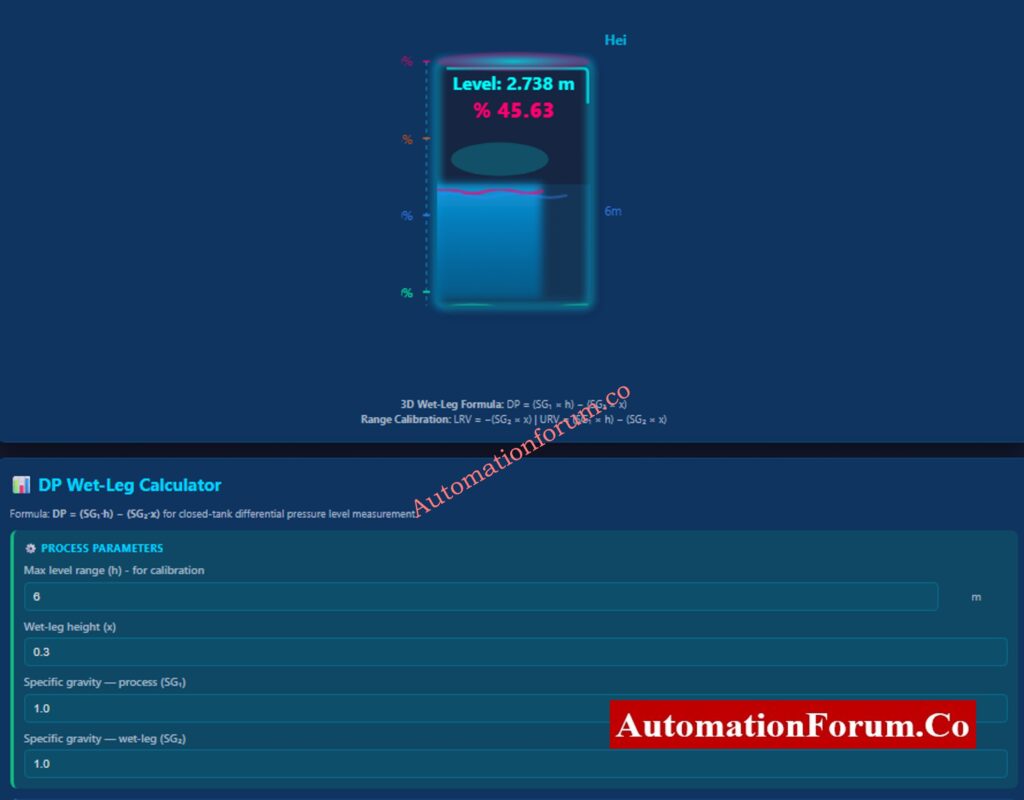
Formula: DP = (SG₁·h) − (SG₂·x) for closed-tank differential pressure level measurement.
In process plants, precise level measurement in closed industrial tanks is essential. The wet-leg method is one of the most dependable ways to guarantee accurate measurement in pressurized tanks, and differential pressure (DP) transmitters continue to be the most trusted technology for this purpose.
By keeping a steady reference liquid column on the transmitter’s low-pressure side, the wet-leg configuration in engineering design prevents measurement drift. EPC engineers, commissioning teams, and maintenance staff will find the provided DP Wet-Leg Level Calculator very helpful as it automates these calculations with built-in formulas, unit conversions, and dynamic visualization.
The entire engineering logic of wet-leg level measurement, including DP formulas, transmitter calibration, mA scaling, and optimal installation techniques, is explained in this guide.
Re-Range Your DP Flow Transmitter Instantly – Smart Online Calculator: DP Flow Transmitter Re-Ranging Calculator
What Is Wet-Leg Level Measurement in Closed Tanks?
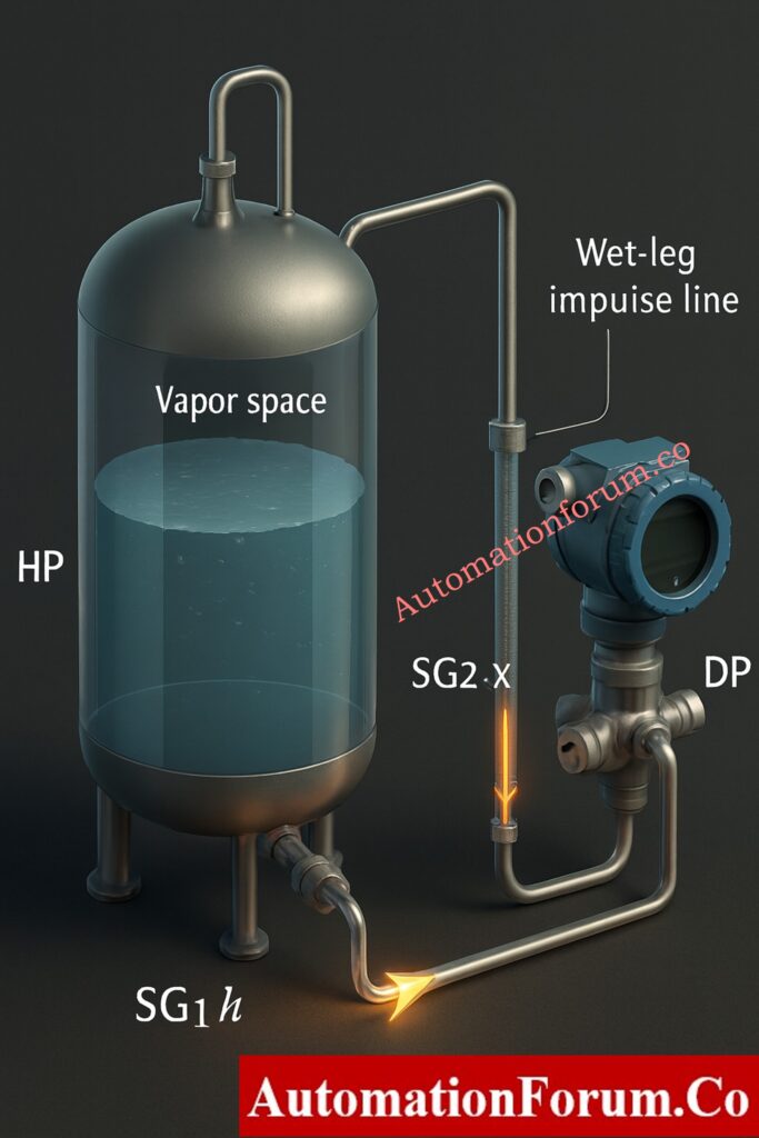
Liquid and vapor are both present in a closed tank. Vapour pressure affects the liquid surface, which in turn affects the low-pressure (LP) side of the transmitter. Variations in vapour pressure lead to errors in DP measurement if they are not compensated for.
An impulse line filled with liquid that is attached to the DP transmitter’s LP side is known as a wet-leg. This ensures that the transmitter only reacts to variations in the liquid level inside the tank by providing a steady hydrostatic reference pressure.
Wet-legs are indispensable in:
- Boiler drums
- Condensate receivers
- Reactors
- Pressurized storage vessels
- Hot liquid tanks where condensation can occur
Condensation, vapour surges, and temperature fluctuations won’t impact the transmitter reading because of to the wet-leg.
Accurate Interface Level Calculation Tool – DP-Based Online Calculator: DP calculator for Interface level measurement
Why Wet-Leg Configuration Improves DP Level Measurement Accuracy
By applying a steady and predictable pressure to the transmitter’s LP port, the wet-leg offers stability. This prevents inconsistent readings, removes line plugging, and adjusts for variations in vapor pressure.
Among the main benefits are:
- Stable zero and span
- Long-term measurement reliability
- Consistent hydrostatic reference
- Elimination of vapour condensation issues
- Suitable for high-temperature and high-pressure tanks
The DP transmitter frequently shows a negative differential pressure at zero level, which is anticipated and utilized in calibration because the wet-leg adds pressure to the LP side.
DP Level Calculation Guide for Open & Closed Tanks – Complete Engineering Tool: Open and Closed Tank DP Level Calculations
DP Formula Used for Wet-Leg Level Calculation
The standard closed-tank wet-leg formula is used by our calculator:
DP=(SG1⋅h)−(SG2⋅x)
Where:
- SG₁ = Specific gravity of process fluid
- SG₂ = Specific gravity of wet-leg fluid
- h = Liquid height inside tank
- x = Wet-leg height
Interpretation:
- The high-pressure (HP) side senses hydrostatic pressure of the liquid column → SG₁ × h
- The low-pressure (LP) side senses pressure created by the wet-leg → SG₂ × x
- The difference between these two pressures is measured by the transmitter.
At every tank level, this formula guarantees precise DP values. The calculator in the document uses the same reasoning.
Open Tank Level Transmitter Calculator – EPC Engineer’s Full Design Guide: Open Tank Level Transmitter Calculator – Complete Guide for EPC Instrumentation Engineers
How to Calculate LRV and URV for DP Transmitters
In order to properly configure a transmitter, we need to compute:
- LRV = Differential pressure at 0% level (empty tank)
- URV = Differential pressure at 100% level (full tank)
LRV (Empty Tank)
LRV=-(SG2⋅x)
This is normally negative, because only the wet-leg acts on the LP side when the tank is empty.
URV (Full Tank)
URV=(SG1⋅H)−(SG2⋅x)
The entire measurement span is represented by this.
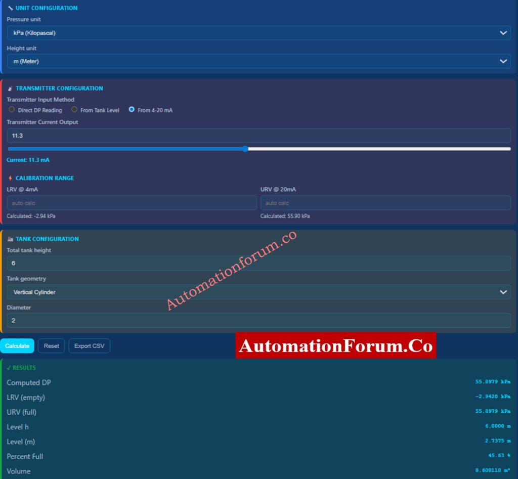
In order to prevent conversion errors and guarantee precise calibration during commissioning, our calculator automatically calculates LRV and URV in a variety of pressure units (kPa, mbar, mmWC, bar, psi, and inH2O).
DP to Flow Calculator – Interactive Differential Pressure Flow Tool for Engineers: Differential Pressure to Flow Calculator – Complete Interactive Tool for Process Engineers
DP Calculation at Any Tank Level (Real-Time Computation)
DP at actual tank levels is necessary for real-time measurement. The formula is still the same:
DPlevel=(SG1⋅hcurrent)−(SG2⋅x)
The provided calculator uses a 3D animated tank to display liquid height and dynamically calculates DP at any level entered by the user. When the level changes, the DP value instantly updates, which is particularly helpful for:
- Control room scaling verification
- I/O checkout
- FAT/SAT activities
- Validation of transmitter configuration
Dry-Leg DP Level Calculator for Closed Tanks – Precise Level Measurement Tool: DP calculator for Dry leg Level measurement – closed tank
Importance of Unit Conversions in Wet-Leg DP Calculations
Units of pressure and height differ between sectors and geographical areas. All major units are supported by the calculator:
Height:
- m, cm, mm
- ft, inches
Pressure:
- Pa, kPa
- mbar
- mmWC, inH₂O
- psi, bar
Multi-unit support ensures:
- Engineering packages remain consistent
- No manual conversion errors
- Smooth integration with OEM data sheets
- Alignment with vendor calibration certificates
Refer the below link for the Displacer Interface Level Transmitter Weight Calculator – Dry Calibration Tool
Understanding Tank Geometry for Volume and Level Output
Volume calculation depends on tank diameter and width, but DP measurement does not. Two tank geometries are included in the calculator:
Vertical Cylindrical Tank
Volume=π(D/2)2⋅h
Rectangular Tank
Volume=Length×Width×h
This helps determine:
- Storage capacity
- Batch processing volumes
- Inventory management values
- Mass balance considerations
The volume result dynamically updates as the level changes.
DP Level & Density Range Calculator – Free Excel Calibration Tool: Excel Tool for DP Type Level and Density Transmitter Calibration Range Calculation
Best Engineering Practices for Wet-Leg Level Design and Installation
Decades of accurate measurement are ensured by proper design and maintenance procedures.
- Maintain a Fully Filled Wet-Leg: Any air bubbles cause rapid drift and unstable readings.
- Use a Fluid with Stable and Known Density: Common choices are water, glycol, or silicone oil.
- Apply Heat Tracing for Outdoor Installations: Prevents freezing and SG variation in cold climates.
- Install Transmitter Below the Tapping Point: Ensures self-filling of impulse lines and prevents vapour trapping.
- Use Condensate Pots for Steam Service: They maintain equal reference height and ensure proper wet-leg filling.
- Verify Zero After Wet-Leg Stabilization: Perform zero check only after the wet-leg reaches thermal equilibrium.
Before calibration and commissioning, engineers can verify all anticipated DP values using this calculator.
Troubleshooting Common Problems in Wet-Leg DP Systems
Wet-leg problems are frequently associated with inaccurate readings in DP level systems. Common symptoms and engineering interpretations are listed below.
- Level Reading Drops When the Tank Fills: HP and LP connections reversed.
- Reading Becomes Noisy and Unstable: Air pockets or partially filled wet-leg.
- DP Range Shifts After Shutdown: Temperature changes affecting wet-leg SG.
- Wrong Level Displayed in DCS: Cause: Incorrect LRV/URV or wrong unit conversion.
- Transmitter Current Does Not Match Expected Level: Incorrect 4–20 mA scaling or range mismatch.
These are resolved by our wet-leg calculator, which provides immediate visualization of the expected DP, level, and mA output mapping.
Refer the below link for the Field Calibration Guide for DP Level Transmitters – Step-by-Step Procedure
Step-by-Step Example: Wet-Leg Level Calculation
Let’s examine a different real-world engineering scenario to gain a clear understanding of how differential pressure behaves in a closed-tank wet-leg configuration. This example shows how the LRV and URV values of the DP transmitter are affected by tank height, process fluid density, and wet-leg fluid density.
Given Process Conditions
| Parameter | Value |
| Process fluid specific gravity (SG₁) | 0.85 |
| Wet-leg fluid specific gravity (SG₂) | 1.10 |
| Tank height (H) | 8 meters |
| Wet-leg height (x) | 0.5 meters |
These numbers show a typical hydrocarbon storage tank with a heavier sealing liquid in the wet-leg and a lighter process fluid than water.
Step 1 – Calculate LRV (Transmitter Output at 0% Level)
LRV occurs when the tank is empty, meaning h = 0.
The standard wet-leg formula:
LRV=−(SG2⋅x)
Substituting values:
LRV=−(1.10×0.5)
LRV=−0.55(meters of water equivalent)
Interpretation:
Because the wet-leg is exerting downward pressure on the LP side, the transmitter will always display a negative differential pressure at zero level.
Step 2 – Calculate URV (Transmitter Output at 100% Level)
URV occurs when the tank is full, meaning:
h=H=8m
Apply the wet-leg DP formula:
URV=(SG1⋅H)−(SG2⋅x)
Substitute values:
URV=(0.85×8)−(1.10×0.5)
URV = 6.8 – 0.55
URV = 6.25meters of water equivalent
Interpretation:
The transmitter detects wet-leg pressure on the LP side and hydrocarbon head pressure on the HP side when the tank is full. The measurement span that can be used is the difference.
Step 3 – Determine Total Transmitter Span
Span = URV – LRV
Span = 6.25 – (-0.55)
Span = 6.80 mWC
This is the range over which the transmitter maps 4-20 mA output.
Step 4 – Example DP Value at 50% Tank Level
Let the tank level be:
h = 0.5H = 4m
Use the formula:
DP50%=(SG1⋅h)−(SG2⋅x)
Substitute values:
DP50%=(0.85×4)−(1.10×0.5)
DP50%=3.4−0.55
DP50%=2.85mWC
Meaning:
The transmitter should produce a DP of 2.85 mWC at half tank level (4 m), which, after scaling, should equal about 12 mA.
Summary for This Example
| Condition | DP (mWC) | mA Output |
| 0% level (empty) | –0.55 | 4.00 mA |
| 50% level | 2.85 | 12.00 mA |
| 100% level (full) | 6.25 | 20.00 mA |
This example shows how transmitter calibration and DP behavior are affected by varying specific gravities and tank heights. Additionally, it clarifies the importance of wet-leg design in maintaining closed-tank level measurements.
How the DP Wet-Leg Calculator Improves Engineering Workflow
The calculator is a full-featured level engineering simulator that provides more than just formula tools.
- Automatic LRV and URV computation
- Real-time DP calculation at any level
- 4-20 mA mapping and reverse mapping
- Highly accurate unit conversions
- 3D tank level animation
- Volume computation for cylindrical and rectangular tanks
- CSV export for documentation
- Error-free design validation
These features are extremely valuable for EPC design, commissioning, DCS configuration, and troubleshooting.
Why Wet-Leg DP Calculation Matters in Instrumentation Engineering
A proven technique for precise and reliable DP measurement in closed tanks is wet-leg level measurement. Instrumentation engineers can guarantee excellent installation and long-term performance by comprehending the wet-leg formula, effects of density, reference leg height, calibration range, and DP-to-level mapping.
All of these engineering concepts are combined in the uploaded DP Wet-Leg Calculator, which makes level calculations for design and field use fast, precise, and error-free. Any instrumentation engineer working with pressurized vessels and DP-based level measurement systems will find it to be a useful tool.
Test Your Knowledge on Zero Elevation Level Measurement Troubleshooting
Refer the below link for the Zero Elevation Level Measurement Troubleshooting Quiz
FAQs – Wet-Leg Level Measurement
What is the purpose of a wet-leg in DP measurement?
A wet-leg provides a constant hydrostatic reference on the LP side. This stabilizes the DP reading in closed tanks where vapor pressure fluctuates.
Why does LRV become negative in a wet-leg system?
Because the wet-leg fluid applies pressure on the LP side even when the tank is empty. This creates a negative differential pressure at 0% level.
What happens if the wet-leg is not fully filled?
Air pockets cause unstable, drifting, and inaccurate DP readings. The transmitter will continuously fluctuate due to inconsistent reference pressure.
Which fluid is best for wet-leg filling?
A fluid with stable and known density such as water, glycol, or silicone oil. The choice depends on temperature, process compatibility, and freezing risk.
What is the difference between wet-leg and dry-leg level measurement?
Wet-leg uses a liquid-filled LP impulse line suitable for closed or hot tanks. Dry-leg uses a vapor-filled LP line and is used for non-condensing applications.