🔧 Open Tank Level Transmitter Calculator
Professional 4-20mA Calibration Tool for Process Instrumentation
🎯 Tank Visualization
Input Parameters
📊 Current Readings
Calibration Data
| % | Level (mm) | Input (mmH₂O) | Output (mA) |
|---|
⚙️ Technical Specifications
📐 Calculation Formulas
📋 Important Notes
- HW = Equivalent Head of Water
- GL = Specific gravity of tank liquid
- HW, MIN = HW at minimum liquid level (Y × GL)
- HW, MAX = HW at maximum liquid level (X × GL)
- Span = (X – Y) × GL in mmH₂O
- Standard output: 4-20 mA for 0-100% measurement range
- Enter precise values with decimals for accurate calculations
- Use slider or input box to simulate different tank levels
Your trusted source for automation tools and calculators
- Understanding the Need for Accurate Level Transmitter Calculations
- Understanding the X and Y Levels in Open Tank Design
- Specific Gravity and Pressure Head in Open Tank Measurement
- 4 to 20 mA Output Mapping in Level Transmitters
- Visualization Benefits in Level Transmitter Calibration
- Engineering Outputs Generated by the Calculator
- Common Mistakes Avoided by Using the Calculator
- Practical EPC Applications of the Calculator
- Why This Calculator is Essential for Modern EPC Instrumentation Design
- Frequently Asked Questions on Open Tank Level Measurement
The open tank level transmitter calibration process is one of the most frequently performed tasks in the field of industrial instrumentation. EPC instrumentation design engineers are in charge of choosing and sizing transmitters, making sure that the range settings are correct, the 4 to 20 mA mapping is appropriate, and the tank measuring points are set up correctly. The Open Tank Level Transmitter Calculator above was made to make this engineering process easier and provide you correct results right away. This article talks about the engineering ideas underlying the calculator and how it helps EPC engineering, commissioning, operations, and maintenance.
Understanding the Need for Accurate Level Transmitter Calculations
Importance of Accurate Level Measurement in EPC Projects
Almost all industrial processes require precise level measurement.
Open tanks are widely used in chemical plants, refineries, utility systems, water treatment units, and storage applications. Whether it is a dosing tank, a sump, a separator, or a process vessel open to atmosphere, an accurate level transmitter configuration is mandatory.
Challenges Faced During Level Transmitter Calibration
When designing level measurement systems for EPC projects, instrumentation engineers encounter a number of difficulties. Identifying the acceptable measurement range, computing the lower and upper range values, accurately mapping the 4 to 20 mA output, and modifying the transmitter scaling in accordance with the liquid specific gravity are a few of the typical needs.
The Open Tank Level Transmitter Calculator solves these problems by generating all required engineering calculations in seconds. It guarantees uniformity throughout design, FAT, SAT, and commissioning processes and removes uncertainty.
Refer the below link for the Checklist: Preventive Maintenance Procedure for Closed Tank Wet Leg Level Measurement
Understanding the X and Y Levels in Open Tank Design
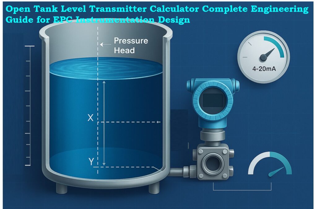
The definition of maximum measurable level X and minimum measurable level Y is one of the calculator’s most important inputs. The tank’s useable measurement span is determined by these two parameters. Many engineers use the wrong LRV and URV because they mistakenly think of the entire tank height as the measurement span.
What is Maximum Level X
The transmitter should measure Maximum Level X, which is the highest usable liquid level. It does not necessarily refer to the tank’s actual height. A number of variables, such as tank freeboard, overflow margin, and nozzle placement, affect X.
Typical EPC examples include
- Tanks where the top 50 mm is left unused due to turbulence.
- Tanks where structural supports limit sensor placement.
What is Minimum Level Y
Minimum Level Y is the lowest point from where the transmitter begins measurement. Dead zones, tank bottom shape, nozzle height, and mechanical constraints all have a role.
Typical EPC examples include
- Nozzle located 200 mm above the tank bottom.
- Displacer and float based systems requiring bottom clearance.
Using X and Y instead of tank height improves transmitter accuracy and avoids calibration mismatches during commissioning.
Specific Gravity and Pressure Head in Open Tank Measurement
Role of Specific Gravity in Level Measurement
Formula for Equivalent Water Head
The calculator uses the formula
Head=Level×SpecificGravity
Impact of Fluid Density and Process Conditions
Accordingly, water at SG 1.0 produces a head that is level.
Water has a higher head than oil at SG 0.80.
Higher head at SG 1.30 is caused by caustic
Tank operating conditions, temperature-dependent density variations, and process fluid changes must all be taken into account by EPC engineers. The calculator calculates pressure equivalents for lowest level, maximum level, and span automatically using specific gravity.
Boiler Drum DP Level Explained Clearly: Understanding Boiler Drum Level Transmitters: Accurate DP Measurement Explained
4 to 20 mA Output Mapping in Level Transmitters
Most industrial level transmitters use a 4 to 20 mA output signal. The mapping from level percent to current output follows a linear relationship.

Based on this logic
0 percent equals 4 mA
50 percent equals 12 mA
100 percent equals 20 mA
The calibration table inside the tool generates a complete listing for 0, 25, 50, 75, and 100 percent. EPC engineers can directly use this table for loop checking, DCS input scaling, FAT records, and commissioning check sheets.
Expert Guide to GWR Troubleshooting & Maintenance: Guided Wave Radar Level Transmitters: Complete Troubleshooting & Maintenance Guide
Visualization Benefits in Level Transmitter Calibration
The tank visualization is a key feature of the calculator. The graphical representation helps engineers understand level movement, transmitter location, and output signal changes in real time.
Benefits of Visualization for EPC Engineers
- Confirms that X and Y levels have been entered correctly
- Shows how transmitter output responds to level movement
- Helps verify nozzle elevation and mounting position
- Facilitates discussion during HAZOP, model review, and design validation
- Assists commissioning teams in understanding the calibration logic
Visualization also supports error prevention, especially when engineers are working with limited tank drawings or incomplete vendor documents.
Quick DP Calculator for Open Tank Levels: DP calculator for open tank level measurements
Engineering Outputs Generated by the Calculator
Instrumentation engineers prepare OR review several documents during the EPC lifecycle. The calculator helps in generating values for the following:
Transmitter Datasheet Values (LRV URV Span)
Transmitter Lower Range Value LRV
Transmitter Upper Range Value URV
Span
Specific gravity corrected pressure equivalents
Loop Design Calculations
Scaled engineering units
4 to 20 mA mapping
Measuring range limits
PLC and DCS Configuration
Engineering units
Zero and span
Input scaling
Alarm limits
Commissioning and Operations Support
Quick reference table for calibration
Troubleshooting documentation
All values are automatically computed and displayed in the results section for direct usage.
Ultimate Level Transmitter Selection Checklist: Level Transmitter Selection Checklist for EPC Engineers – Step-by-Step Guide
Common Mistakes Avoided by Using the Calculator
Instrumentation engineers frequently make certain mistakes when manually calculating transmitter ranges. The tool avoids these issues.
Using Tank Height Instead of Usable Range
Tank height is not equal to measurement range. Only X minus Y defines the actual span.
Ignoring Specific Gravity
If a transmitter is calibrated with wrong specific gravity, the displayed level will always be incorrect.
Incorrect 4 to 20 mA Scaling
Incorrect mapping leads to wrong DCS indication and alarms triggering at incorrect levels.
Calibration Using Water for Low SG Liquids
Many commissioning teams calibrate transmitters with water even when the process liquid has SG less than one. This results in incorrect level indication.
The calculator highlights all these issues and provides precise values to eliminate calibration errors.
Top 15+ Level Measurement Calculators Pack: 15+ Collection of Level Measurement Calculators for Industrial Instrumentation
Practical EPC Applications of the Calculator
All phases of EPC engineering and commissioning benefit greatly from the tool.
During Basic Engineering
aids in determining the appropriate instrument type and range
aids in the creation of the I O list and instrument index during detail
During Detail Engineering
aids in determining the appropriate instrument type and range
aids in the creation of the I O list and instrument index during detail
During FAT and SAT
provides a cross-checking calibration table.
supports functional testing and loop checks.
aids in verifying alarm configurations
During Commissioning and Startup
allows technicians to compare the transmitter’s output to the tank’s real level.
aids in identifying installation problems
guarantees that control systems display levels accurately.
Instant Zero-Suppression DP Calculator: DP calculator for Zero suppression – open tank level measurement
Why This Calculator is Essential for Modern EPC Instrumentation Design
Maintaining process stability, avoiding tank overflow, safeguarding pumps, and guaranteeing seamless operations all depend on accurate level measurement. Unexpected plant shutdowns, trip failures, and hazardous circumstances might result from improper configuration.
With its accurate pressure equivalents, this calculator streamlines the entire process for EPC engineers.
Correct mapping from 4 to 20 mA
Accurate range computations
Automated visualization
Table of calibration references
The technology guarantees consistency throughout all project phases, lowers field errors, and enhances engineering quality.
For instrumentation and EPC design engineers, the Open Tank Level Transmitter Calculator is a vital technical tool. It improves level transmitter configuration by adding precision, lucidity, and uniformity. The calculator reduces human error and improves the caliber of EPC outputs by fusing accurate engineering formulas, real-time visualization, and an intelligent calibration table.
This guide provides an in depth understanding of how the calculator works and how engineers can use it throughout design, commissioning, and operations. It is a must have tool for any engineer working with open tank level measurement and 4 to 20 mA signal configuration.
Master DP Calculations for Open & Closed Tanks: Open and Closed Tank DP Level Calculations
Frequently Asked Questions on Open Tank Level Measurement
What is the formula for open tank level measurement?
The standard formula for open tank level measurement is based on hydrostatic pressure.
Since the tank is open to atmosphere, the transmitter measures only the liquid head.
Formula
Level = Pressure Head ÷ Specific Gravity
Where
Pressure Head is in mmH₂O
Specific Gravity is dimensionless
Example
If the measured head is 480 mmH₂O and SG = 0.8
Level = 480 ÷ 0.8 = 600 mm
What is the formula used to determine the level in an open tank?
For an open tank, level is determined using the liquid column and density relationship.
Formula
Measured Pressure = Level × Specific Gravity
Therefore
Level = Measured Pressure ÷ Specific Gravity
This formula is used when the transmitter output is in mmH₂O or kPa and you want to convert it to actual liquid height.
How to calculate tank level?
Tank level can be calculated in two ways depending on the available data:
1. Using Hydrostatic Pressure
Level = Pressure Head ÷ Specific Gravity
2. Using Percentage from a 4 to 20 mA Signal
Level = LRV_Level + (Percentage × Span_Level)
Percentage = (mA − 4) ÷ 16
This allows engineers to convert transmitter output into actual tank level.
How to calculate URV and LRV?
For an open tank, URV and LRV are calculated based on the minimum and maximum measurable liquid heights.
LRV (Lower Range Value)
LRV = Minimum Level × Specific Gravity
URV (Upper Range Value)
URV = Maximum Level × Specific Gravity
Span
Span = URV − LRV
Example
Minimum Level (Y) = 200 mm
Maximum Level (X) = 800 mm
Specific Gravity = 0.8
LRV = 200 × 0.8 = 160 mmH₂O
URV = 800 × 0.8 = 640 mmH₂O
Span = 480 mmH₂O
These values become the calibration range for the transmitter.
How to calculate LRV value?
The LRV value represents the transmitter output at the minimum measurable level.
Formula
LRV = Minimum Level (Y) × Specific Gravity
LRV is always pressure-based for hydrostatic level transmitters.
For example, if Y = 150 mm and SG = 1.0
LRV = 150 mmH₂O
This becomes the input pressure that corresponds to 4.00 mA.
What is URV and LRV?
URV and LRV are calibration endpoints of a level transmitter.
LRV (Lower Range Value)
This is the pressure or head when the tank is at minimum measurable level.
LRV corresponds to 4.00 mA output.
URV (Upper Range Value)
This is the pressure or head when the tank is at maximum measurable level.
URV corresponds to 20.00 mA output.
For open tanks
LRV = Y × SG
URV = X × SG
Where X and Y are maximum and minimum levels.
Complete Calibration Procedures for Level Devices: Calibration Procedures for Level Measurement Devices