- What is the principle of capacitance type level transmitter?
- Principle of capacitance type level measurement:
- How does capacitive pressure transmitter work?
- What is the formula for capacitance level?
- How do you install a level transmitter?
- Installations and wire connection
- How do you troubleshoot a level transmitter?
- Troubleshooting of capacitance type level transmitter:
- 1. When the tank level is low or empty, the output value remains over 20.0 mA.
- 2. When the level is increasing, the unit won’t detect any material, or the output doesn’t move sufficiently.
- 3. One of the alert conditions is shown by the output (3.6 or 21 mA)
- 4. Unstable output
- 5. No output
- 6. Erratic or incorrect readings
- 7. Output reading 3.6 mA
- 8. Transmitter reading 5% or more in inaccuracy in output
- 9. After installing the Concentric Shield probe, readings were found to be inaccurate.
What is the principle of capacitance type level transmitter?
Principle of capacitance type level measurement:
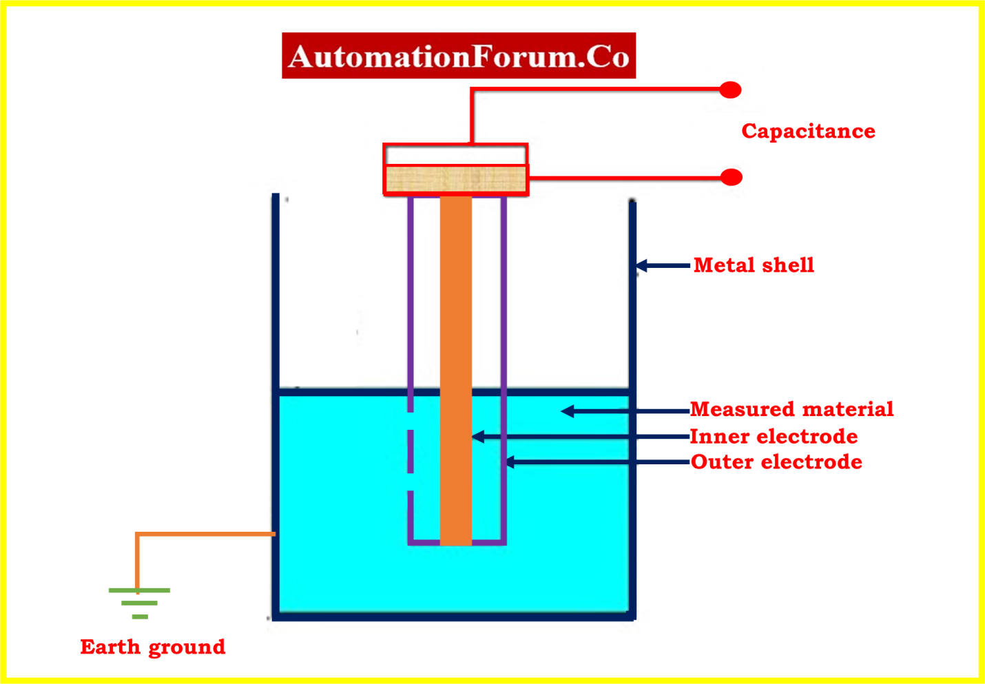
A capacitance type level transmitter is a device used for measuring the level of liquids or solids in a tank, vessel or container. It works by utilizing the principle of capacitance, which is the ability of a system to store electrical energy in an electric field.
How does capacitive pressure transmitter work?
In a capacitance type level transmitter, two electrodes (often referred to as “plates”) are placed in close proximity to the material whose level is to be measured. One electrode is kept at a fixed distance from the material, while the other electrode is connected to a movable probe. As the level of the material changes, the distance between the two electrodes also changes, causing a change in capacitance.
This change in capacitance is then converted into an electrical signal and transmitted to a control system or a display unit, which can then be used to determine the level of the material. The accuracy and reliability of a capacitance level transmitter are dependent on several factors, such as the material properties of the electrodes, the frequency of the electrical signal used, and the stability of the environment in which the measurement is taken.
Capacitance type level transmitters are widely used in a variety of applications, including chemical processing, oil and gas production, water treatment, and food and beverage production.
What is the formula for capacitance level?
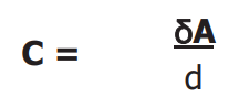
A capacitor made by two parallel plate electrodes has a capacitance of
Where,
C = capacitance
? = dielectric constant of the insulating material
A = effective area of the conductors
d = distance between the conductors
1) Directly proportional to electrode area “A”
2) inversely proportional to the plates’ separation (d).
3) Directly proportional to the dielectric ‘ä’ placed between them
The metal container wall surrounding the level sensor and its probe form an electrical capacitor when the vessel is empty. This initial capacitance happens between the electrode level sensor and the metal wall. This capacitor’s value rises when the sensor is submerged in liquid, and the capacitance change is detected and transformed into an output signal proportionate to the capacitance change.
An incompletely or completely insulated flexible or solid rod probe is used depending on the application’s needs. The electronic capacitance current and transducer are located in the probe head.
How do you install a level transmitter?
Installations and wire connection

- Carefully unpack the level indicator.
- Check that you have all the necessary equipment and tools, including the transmitter, a mounting kit, conduit, wiring, and appropriate electrical fittings.
- Choose a spot on the tank for the probe where there is the least amount of turbulence.
- Probe should be placed so that material doesn’t flow directly onto it.
- Make sure that the level transmitter’s process connection matches the one on the tank.
- The reference electrode or the side of the tank should be parallel to the sensing electrode.
- With the required gasket and bolts, secure the probe unit to the tank.
- In the event that an electronic device is installed outside, it is necessary to protect it from direct sunlight by enclosing it in sheets.
- When putting the flexible probe into the tank, do it carefully because rough handling could damage the probe and its insulation.
- According to the provided wiring code, connect the level transmitter.
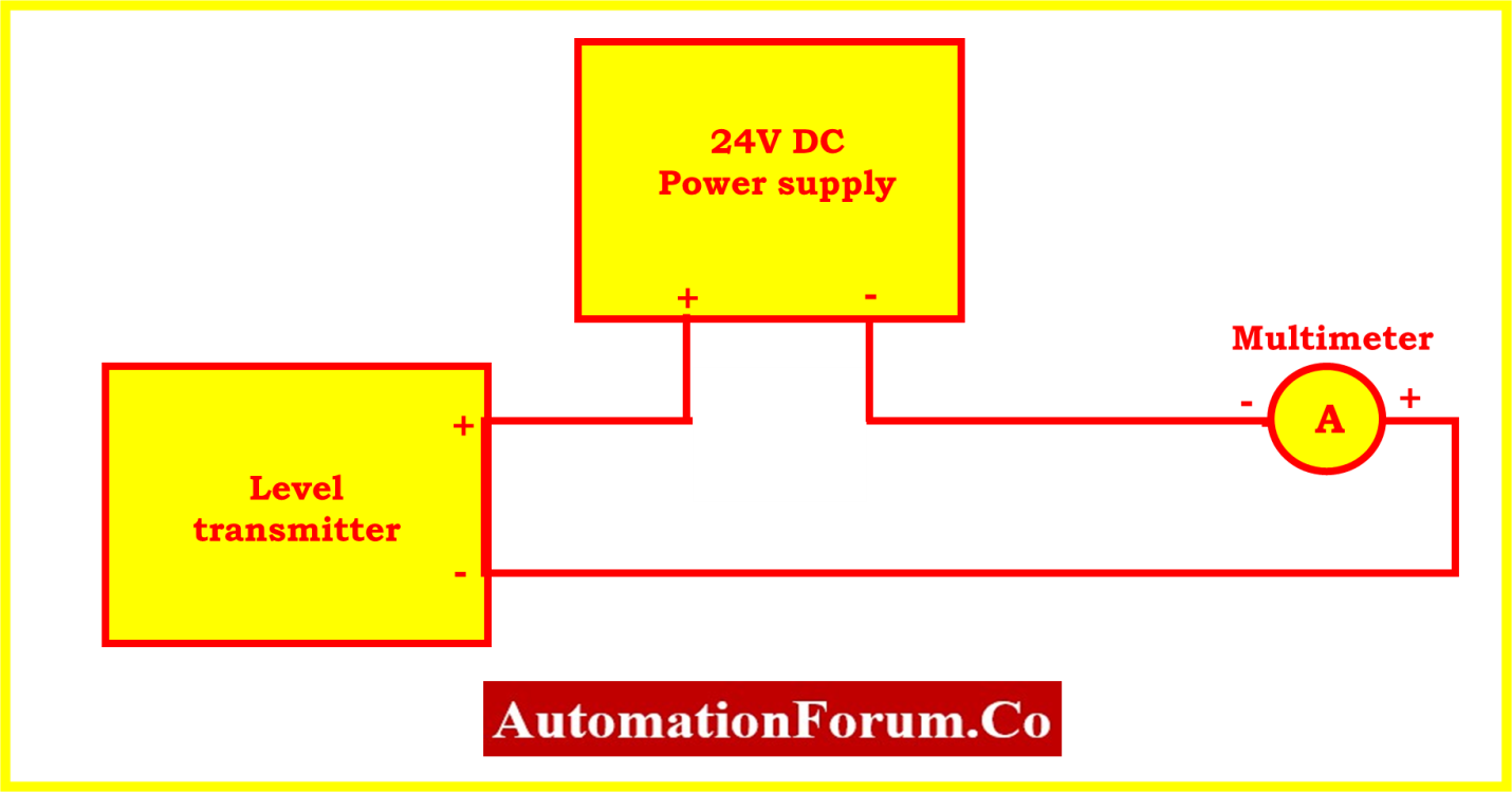
- Connect the 24 VDC power to the appropriate polarity (+ve and ve) for the input power.
- The output may be examined by connecting the multimeter in series as shown below. This loop-powered transmitter can be linked to a PLC or a process controller.
- The transmitter is factory calibrated, so it doesn’t need to be calibrated, but if it does, follow the steps below.
How do you troubleshoot a level transmitter?
Troubleshooting of capacitance type level transmitter:
Here is some of the common troubleshooting guideline for a capacitance type level transmitter
1. When the tank level is low or empty, the output value remains over 20.0 mA.
| S.no | Possible cause | Action required |
|---|---|---|
| 1 | Inadequate range selection. | Check that the device is set to the appropriate range. Examine the area for the presence of water and remove it if it is found. |
| 2 | An issue with the transmitter | Replace out the faulty electronic component with a functional one. |
| 3 | There was moisture in the probe’s conduit. | Examine the area for the presence of water and remove it if it is found. |
| 4 | Insulation slits cut into the probe | Inspect the insulation of the probe for any rips, cuts, or worn patches; if you find any, replace it with a new probe. |
2. When the level is increasing, the unit won’t detect any material, or the output doesn’t move sufficiently.
| S.no | Possible cause | Action required |
|---|---|---|
| 1 | Inadequate range selection. | Check that the device is set to the appropriate range. Examine the area for the presence of water and remove it if it is found. |
| 2 | An issue with the transmitter | Replace out the faulty electronic component with a functional one. |
3. One of the alert conditions is shown by the output (3.6 or 21 mA)
| S.no | Possible cause | Action required |
|---|---|---|
| 1 | Short circuit between the banana connection and the housing or in the probe. | Verify the probe’s connection to the board. Change the probe. |
| 2 | Conductive link between the probe and the vessel wall. | Remove any debris in order to eliminate the bridge between the probe and the vessel wall. |
| 3 | Inadequate range selection. | Check that the device is set to the appropriate range. Examine the area for the presence of water and remove it if it is found. |
| 4 | Insulation slits cut into the probe | Inspect the insulation of the probe for any rips, cuts, or worn patches; if you find any, replace it with a new probe. |
4. Unstable output
| S.no | Possible cause | Action required |
|---|---|---|
| 1 | Poor connection to the earthing terminals | Establishing an accurate ground connection. |
| 2 | Radio frequency interference | Ensure that the housing covers are secured by tightening them all the way. |
| 3 | The presence of waves or agitation in fluids | When agitation or wave action is stopped, the output should be steady. If the output is consistent, install the stilling well for the probe. |
5. No output
| S.no | Possible cause | Action required |
|---|---|---|
| 1 | Check the power supply | Ensure that the power supply to the level transmitter is stable and within the specified range. |
| 2 | Check the wiring | Ensure that the wiring is correct and securely connected to the level transmitter and control room |
6. Erratic or incorrect readings
| S.no | Possible cause | Action required |
|---|---|---|
| 1 | Conductive liquid that is not grounded, contained inside a fiberglass vessel. | There is a possibility that the process has to be grounded. A dual probe or concentric shield could be necessary. |
| 2. | Temperature fluctuations during the manufacturing process, which cause damage to the dielectric. | Check the working conditions, and if necessary, communicate to the manufacturer about it. Also refer the instrument working condition in the instrument specification and ensure that the temperature and humidity conditions are within the specified range for the level transmitter to work properly. |
7. Output reading 3.6 mA
| S.no | Possible cause | Action required |
|---|---|---|
| 1 | In the probe head, there is a wiring short circuit from the shield to the ground. | Wiring should be examined and corrected. |
| 2 | Wire connection is not connected to the transmitter is the probe. | It is necessary to create a good connection between the probe and the transmitter. |
8. Transmitter reading 5% or more in inaccuracy in output
| S.no | Possible cause | Action required |
|---|---|---|
| 1 | Accumulation of conductive particles on the probe. | Probe must be inspected, and then cleaned. |
| 2 | An issue with the transmitter | Replace the electronic transmitter with a new one. |
9. After installing the Concentric Shield probe, readings were found to be inaccurate.
| S.no | Possible cause | Action required |
|---|---|---|
| 1 | If the probe makes contact with the wall of the concentric shield, then some of the material in the shield may bridge or partly plug. | Place the probe in the middle of the circular shield (may require probe centering adapter). |
| 2 | There is an issue with the calibration. | Re-calibrate transmitter. |
| 3 | Vent holes of concentric shield may be sealed | Remove any debris from the probe, then reinstall it.Remove any debris from the holes, and check to make sure there aren’t any blockages |