
- What is a Loop Folder in Instrumentation?
- Why Is a Loop Folder Required for Commissioning?
- Instrument Loop Folder Documents and Contents
- Typical Loop Folder Documents and Their Purpose
- P and ID vs Instrument Location Drawing in a Loop Folder
- Pressure Transmitter Loop Folder Example
- Control Valve Loop Folder Example
- How to Prepare an Instrument Loop Folder for Commissioning
- How is a Loop Folder Used During Loop Checking?
- Common Loop Folder Problems Found During Commissioning
- Instrument Loop Folder Acceptance Checklist
- How Loop Folders Are Used Throughout the Project Lifecycle
- Digital Instrument Loop Folders in EPC Projects
- Instrument Loop Folders for Brownfield and Revamp Projects
- Relationship Between Instrument Loop Documents
- What Makes a Good Instrument Loop Folder?
- Frequently Asked Questions About Instrument Loop Folders
- Conclusion: Instrument Loop Folder
A loop folder is a controlled documentation package prepared for an individual instrumentation or control loop. It brings together the engineering documents, installation records, calibration evidence, wiring information, test results and commissioning records required to prove that the loop has been correctly installed, tested and accepted.
For an instrumentation engineer, the value of the package is not the number of documents inside it. Its real value is traceability from the process connection and field instrument through the cable system and control system to the final control function.
The exact contents vary according to project specifications, client requirements, instrument type, control system and commissioning procedure.
What is a Loop Folder in Instrumentation?
What Does an Instrument Loop Folder Contain?
An instrument loop folder provides one controlled location for information associated with a specific loop.
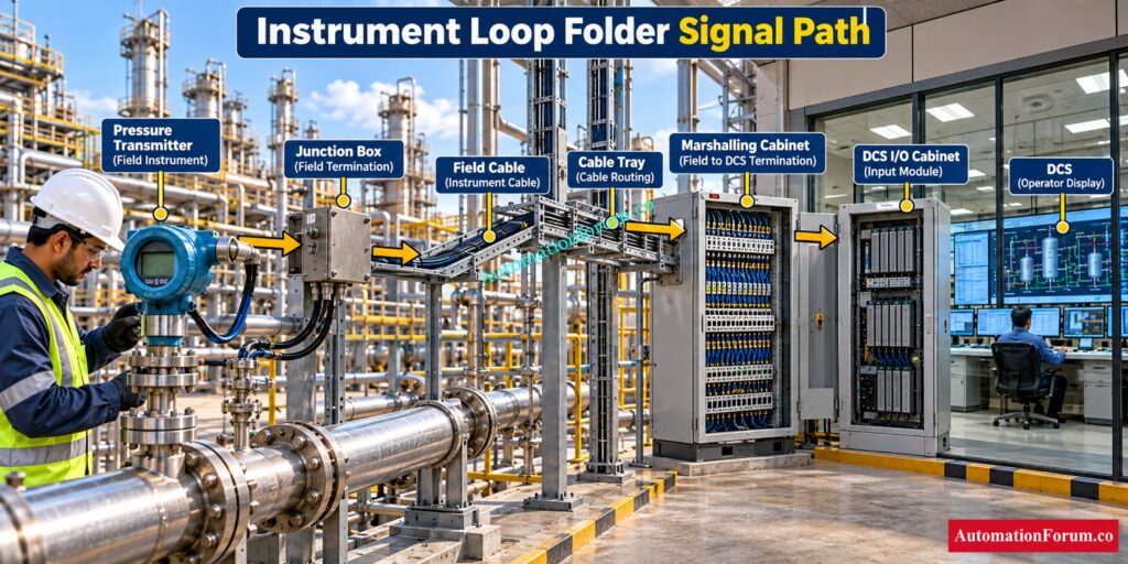
For a pressure measurement loop, the documentation can connect the pressure connection, transmitter, field cable, junction box, marshalling cabinet, I O channel and DCS display. For a control valve loop, it can extend from the DCS output through wiring, positioner and actuator to the valve and its process response.
What Is the Signal Path Covered by a Loop Folder?
A typical signal path may include the following:
- Primary process element
- Field instrument
- Junction box
- Field cable
- Marshalling cabinet
- Interposing component where applicable
- PLC, DCS or SIS I O
- Control system configuration
- Final control element where applicable
The folder connects these engineering points with actual inspection and test evidence.
Refer the below link for the Loop Checking Field vs Control Room Reading Mismatch Explained
Why Is a Loop Folder Required for Commissioning?
Why is a loop folder Required?
A loop folder is used throughout an EPC project rather than only during commissioning.
It helps engineers verify design information, installation, cable termination, calibration, loop continuity, signal transmission, control system configuration and functional response.
Instrument Commissioning Documentation
During QA QC review, it provides evidence that required inspections and tests have been completed. During commissioning, it allows the engineer to work from approved information instead of searching through multiple document registers.
It also supports punch clearance, client inspection, system handover, as built documentation, troubleshooting, maintenance and future plant modifications.
IEC 62382:2024 defines electrical and instrumentation loop check procedures for activities between completed loop construction and the beginning of cold commissioning, including new installations and revamp work.
Calculate Junction Box Loading Before Field Installation: Junction Box Load Calculator
Instrument Loop Folder Documents and Contents
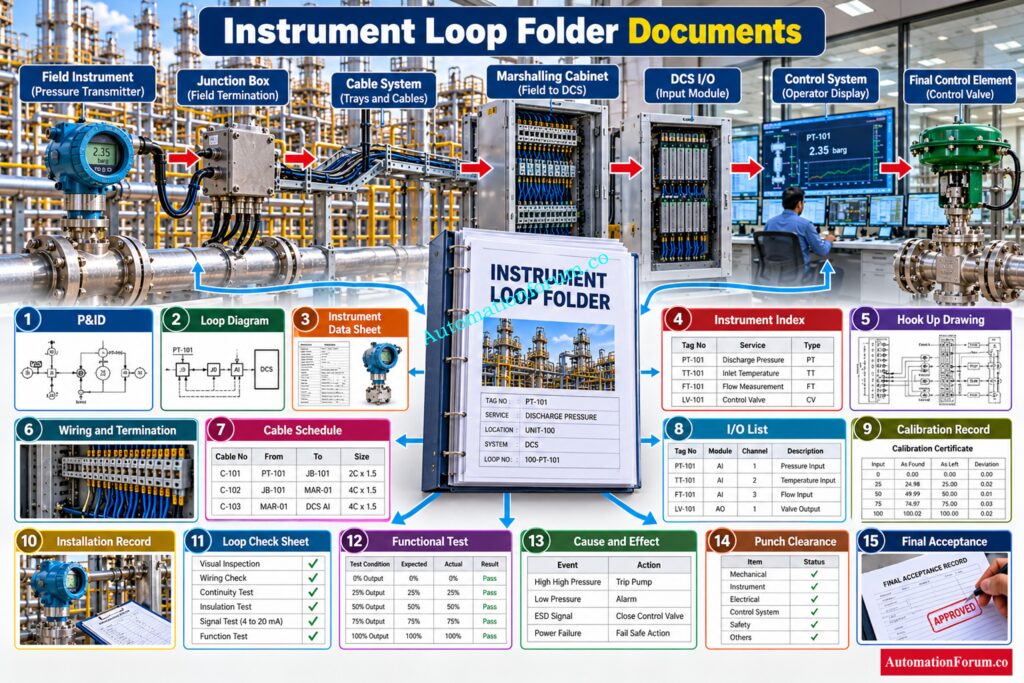
The exact document list is project specific. A typical package may contain:
- Loop folder cover sheet
- Instrument loop diagram
- P and ID (Piping and Instrumentation Diagram) extract
- Instrument data sheet
- Instrument index reference
- Instrument specification
- Hook up drawing
- Wiring diagram
- Termination diagram
- Junction box termination information
- Cable schedule
- Cable routing information
- Instrument location drawing
- Installation detail or elevation drawing
- I O list
- Calibration certificate
- Calibration report
- Installation inspection record
- Cable continuity report
- Insulation resistance report where applicable
- Pre loop check record
- Loop check sheet
- Functional test record
- Alarm and trip test record where applicable
- Interlock test record where applicable
- Cause and Effect reference where applicable
- Punch list
- Punch clearance record
- Configuration information where applicable
- Final commissioning or acceptance record
Not every loop requires every document. A temperature transmitter, control valve, motor operated valve and safety instrumented function can have significantly different documentation requirements.
Verify Instrument Range Before Calibration And Loop Testing: Instrument Range Calculator | Calculate Span, Rangeability, Turndown Ratio & Calibration Range
Typical Loop Folder Documents and Their Purpose
| Document | What it verifies | How it is used during commissioning |
| P and ID extract | Process connection and tag relationship | Confirms the correct process loop |
| Loop diagram | Signal path and connections | Used for field to system verification |
| Data sheet | Instrument specification and range | Confirms device configuration |
| Hook up drawing | Physical installation | Verifies mounting and connections |
| Cable schedule | Cable identification | Confirms cable routing and termination |
| I O list | System channel assignment | Confirms correct PLC or DCS channel |
| Calibration record | Measurement accuracy | Confirms instrument calibration |
| Installation record | Physical installation | Confirms construction completion |
| Loop check sheet | Complete signal path | Records loop test results |
| Functional test | Operational response | Confirms required control action |
| Cause and Effect | Logic relationship | Verifies alarm, trip or interlock action |
Follow This Proven Pressure Transmitter Loop Testing Method: Method Statement for Loop Checking of Pressure Transmitter Loop
P and ID vs Instrument Location Drawing in a Loop Folder
These documents answer different engineering questions.
| Document | Main Purpose | Information Provided |
| P and ID | Shows the process and instrumentation relationship | Equipment, piping, process connections, instrument tags and control functions |
| Instrument Location Drawing | Shows the physical installation location | Instrument position, mounting arrangement, physical location and elevation |
For example, a pressure transmitter may be shown on the P and ID as part of a pressure control loop. The location drawing can show its actual field position, mounting arrangement and elevation.
Using both documents during field verification prevents an engineer from confirming the correct tag while overlooking an incorrect physical installation.
Discover The Correct MOV Loop Testing Procedure: How to do loop checking of Motor operated valve?
Pressure Transmitter Loop Folder Example
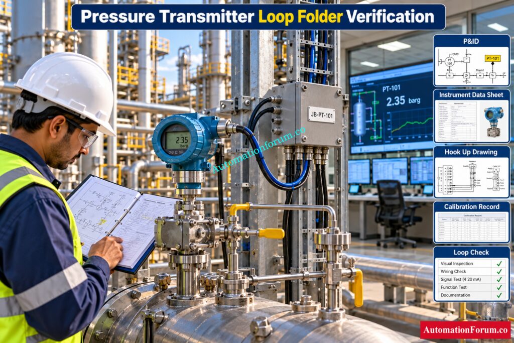
Consider a pressure transmitter connected to a process vessel.
- The engineer first verifies the process connection and transmitter tag against the P and ID and data sheet.
- The hook up drawing then confirms the installation configuration.
- The field cable number and termination are verified against the loop diagram and cable schedule.
- First inspect the junction box terminals then the marshaling cabinet.
- The I O list specifies which DCS channel to use.
- During loop checking a suitable test signal is applied and the engineer checks that the DCS receives the proper signal and the desired process value is displayed.
- The alarm response is validated to the permitted setup or test process if applicable.
- The loop check result is then recorded in the appropriate test record. This creates a traceable path from the field device to the operator display.
Fix These Instrument Loop Problems Before Startup: Common Instrument Loop Check Problems During Startup
Control Valve Loop Folder Example
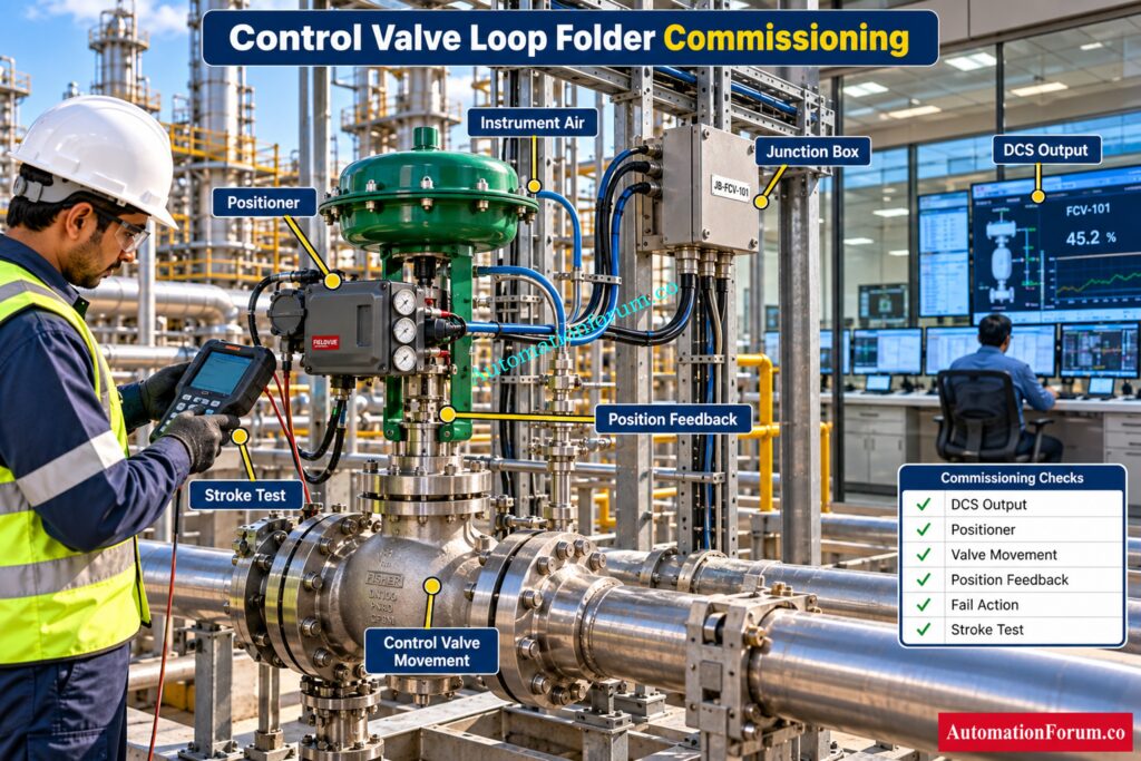
A control valve package requires additional checks because it includes a final control element.
- The engineer verifies the valve tag, valve specification, actuator, positioner, air supply and signal wiring.
- The DCS output channel is checked against the permitted loop information.
- During testing the command signal is applied and the movement of the valve is checked.
- Position feedback is examined if available.
- The required fail action is verified against the approved engineering information and applicable test procedure.
- Calibration and stroke testing records provide evidence that the valve responds correctly.
- This documentation becomes particularly useful when a valve does not reach the required position during commissioning.
- Engineers can trace the problem through configuration, wiring, positioner, air supply, actuator and mechanical movement instead of troubleshooting by guesswork.
Verify Live 4 To 20 mA Signals Safely: Live Signal Verification 4 to 20 mA Loop Standard Operating Procedure (SOP)
How to Prepare an Instrument Loop Folder for Commissioning
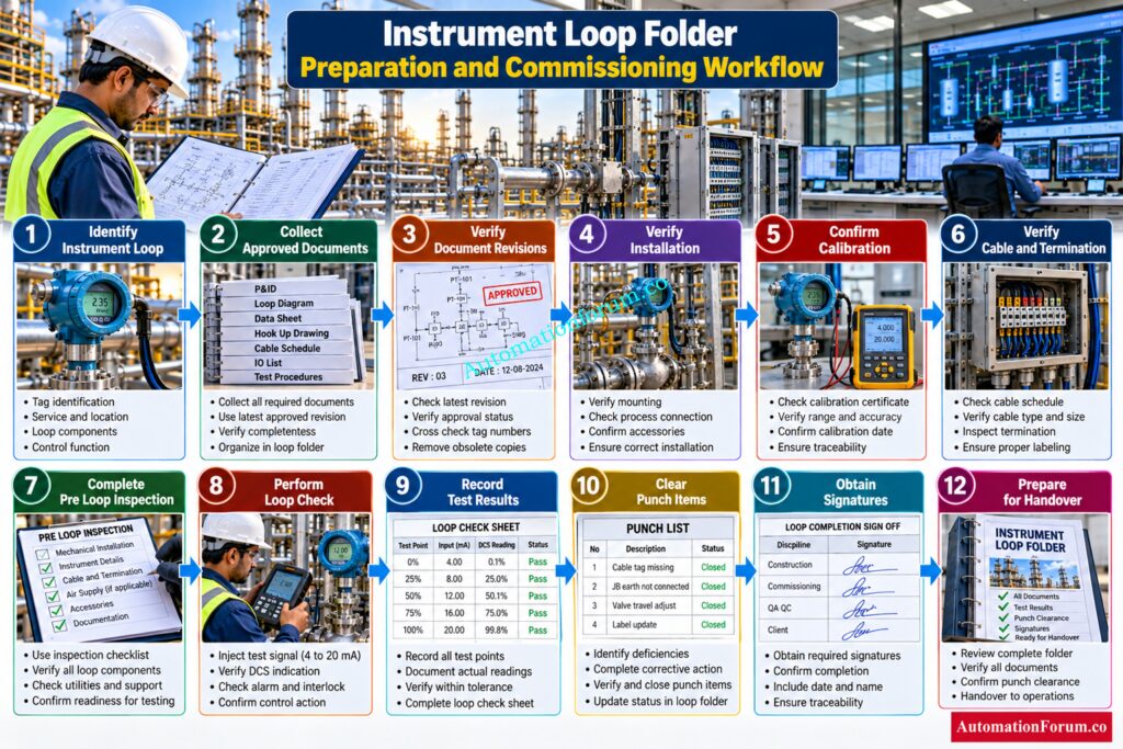
A practical preparation sequence is:
- Identify the instrument loop and confirm its tag.
- Obtain the latest approved engineering documents.
- Collect the documents applicable to that loop.
- Check document revision numbers.
- Confirm physical installation status.
- Confirm calibration status.
- Verify cable identification and termination.
- Review continuity and insulation testing where applicable.
- Complete the pre loop inspection.
- Perform the loop check.
- Record actual test results.
- Record abnormalities and punch items.
- Fixed noted issues.
- Run the necessary tests again after rectification.
- Obtain required signatures.
- Update the loop status.
- Prepare the completed package for review and handover.
This sequence is more effective when documentation is built progressively during construction and pre commissioning rather than assembled at the end of the project.
Refer the below link for the Cold and Hot Loop Checking in Automation: Key Differences and Step-by-Step Procedures
How is a Loop Folder Used During Loop Checking?
During loop checking, the folder becomes the working reference for the commissioning engineer.
- Suppose a pressure transmitter is installed and calibrated.
- The engineer confirms the transmitter details, checks the cable connection, verifies the junction box termination and follows the signal through marshalling to the DCS I O channel.
- A test signal is then simulated.
- The engineer compares the DCS indication with the intended value and confirms alerts, control functions as relevant.
- IEC loop check guidance also emphasizes documenting loop check results and maintaining updated information that reflects the completed installation.
A good loop folder therefore provides both the reference information and the documentary evidence for the test.
Check Instrument Loop Current Without Creating Dangerous Faults: How to Safely Check the mA Current of an Instrument Loop Using a Multimeter
Common Loop Folder Problems Found During Commissioning
- Outdated drawing revision: There could be an old drawing that is not the latest approved revision in the loop folder.
- Incorrect instrument tag: The instrument tag in the documentation does not correspond with the instrument installed in the field.
- Missing calibration certificate: The loop may be ready for inspection but the necessary calibration certificate may be absent.
- Wrong cable number: The cable number in the loop folder may not correspond to the cable actually attached to the instrument.
- Incorrect termination reference: The field ending may not correspond to the terminal numbers in the document papers.
- Missing hook up drawing: Without the hook up drawing it can be difficult to verify that the instrument was placed appropriately.
- Range and DCS mismatch: Instrument range may not match the range defined in the DCS.
- Incorrect I O channel: The instrument is linked to a different I O channel than shown in the documents.
- Incomplete loop check sheet: Some of the test data are missing from the loop check sheet.
- Unsigned test record: Records of completed inspections or tests may lack required signatures.
- Open punch item: The loop may have some open punch item that needs to be cleared.
- P and ID mismatch: The approved P and ID could be based on a different condition than discovered in the field.
- Incorrect valve fail action: The specified fail action of the control valve might not be the actual field condition.
- Document and field mismatch: The engineering documents, field installation and test results should all match before final acceptance.
- Incorrect final status: The loop folder should clearly show whether the loop is ready for commissioning, handover or further corrective action.
Find And Fix Control Valve DCS Loop Problems: Checklist for Troubleshooting Control Valve in DCS Loop
Instrument Loop Folder Acceptance Checklist
Before submitting a loop package for client review, confirm:
- Correct instrument tag
- Correct document revision
- Complete applicable documentation
- Calibration completed
- Installation completed
- Wiring verified
- Continuity verified where applicable
- Loop check completed
- Functional testing completed where applicable
- Alarm or trip verification completed where applicable
- Punch items addressed
- Required signatures completed
- Final loop status updated
- As built changes incorporated where required
Know Exactly When Loop Checks Become Functional Tests: Loop Check vs Functional Test in Instrumentation Commissioning
How Loop Folders Are Used Throughout the Project Lifecycle
| Project stage | How the documentation is used |
| Engineering | Defines the intended loop arrangement |
| Construction | Guides installation and termination |
| Pre commissioning | Confirms readiness for testing |
| Commissioning | Supports loop and functional testing |
| Start up | Provides verified loop information |
| Handover | Provides traceable acceptance evidence |
| Maintenance | Supports troubleshooting and future work |
ISA describes loop diagrams as useful across design, construction, startup, operation, maintenance and modification activities.
Check Barrier Earth Fault Risks Before Energizing Loops: IS Barrier Earth Fault Current Calculator | Intrinsic Safety Loop Design Tool
Digital Instrument Loop Folders in EPC Projects
Many projects now manage loop documentation electronically through controlled document systems.
A digital loop package can provide revision control, searchable records, electronic approvals, punch tracking, commissioning progress information and controlled as built records.
The important principle remains the same. Digital storage does not replace engineering control. The latest approved document, correct instrument tag and verified test evidence still need to be maintained.
Solve Difficult 4 To 20 mA Loop Faults Faster: How to do troubleshooting of a 4-20mA loop?
Instrument Loop Folders for Brownfield and Revamp Projects
Brownfield projects require particular attention because existing documentation may not match field conditions.
An engineer may encounter an existing loop, a modified loop, a newly installed loop or a decommissioned loop. Field verification is therefore essential before preparing the final documentation package.
Where the field differs from the existing drawing, the discrepancy should be investigated, documented and resolved through the project change and document control process.
Master Control Valve Stroke Testing Before Commissioning: Control Valve Stroke Checking -Complete Procedure, Errors, Setup, and FAQ
Relationship Between Instrument Loop Documents
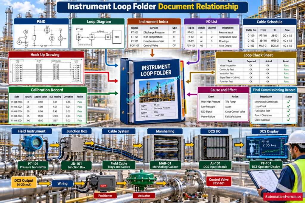
The loop folder acts as the controlled package that connects several individual documents.
- The P and ID explains the process relationship.
- The loop diagram explains the signal and physical connections.
- The instrument index identifies the instrument.
- The I O list identifies the control system channel.
- The cable schedule identifies the cable.
- The hook up drawing explains installation.
- The calibration record proves measurement verification.
- The loop check sheet proves signal path testing.
- The Cause and Effect document supports applicable alarm, trip and interlock testing.
Together, these records provide a much clearer engineering picture than any individual document can provide.
Understand FAT SAT And SIT Testing Before Handover: FAT vs SAT vs SIT: Three Critical Tests
What Makes a Good Instrument Loop Folder?
A good loop folder should be complete, traceable, correct, current, consistent and easy to review.
Every record should relate to the correct instrument tag. Test results should be supported by actual evidence and required signatures. Open issues should be clearly identified and controlled.
Find Out Why Your Pressure Transmitter Hits 22 mA: Why Is My Pressure Transmitter Showing 22 mA? Complete Troubleshooting Guide for Instrument Engineers
Frequently Asked Questions About Instrument Loop Folders
What is a loop folder in instrumentation?
A loop folder is a controlled documentation package containing the engineering, installation, calibration, testing and commissioning records for an instrument loop.
It gives engineers a clear traceable record from field installation through loop checking, commissioning and final handover.
What documents are included in a loop folder?
A typical loop folder may include the P and ID, loop diagram, instrument data sheet, hook up, wiring details, calibration records and loop check sheet.
The exact document list depends on the project specification, instrument type and client requirements.
Why is a loop folder required for commissioning?
It gives commissioning engineers the approved drawings and records needed to verify the complete instrument loop.
It also provides documented evidence that installation, calibration, wiring and functional testing have been completed.
Understand Where Signals Really Connect In Control Systems: Marshalling Panel vs Junction Box vs System Cabinet
What is the difference between a loop folder and a loop diagram?
A loop diagram shows the signal path and physical connections between the field instrument and control system.
A loop folder contains the loop diagram together with the engineering, inspection, calibration and commissioning records for that loop.
Who prepares the loop folder?
Loop folder preparation normally involves engineering, construction, QA QC, pre commissioning and commissioning teams.
Responsibilities are normally defined by the project documentation and commissioning responsibility matrix.
Verify Intrinsic Safety Parameters Before Final Loop Design: Intrinsic Safety Entity Parameter Calculator for Reliable Hazardous Area Loop Design
When should a loop folder be prepared?
Loop documentation should be developed progressively as installation, inspection, calibration and testing activities are completed.
Preparing it early helps the commissioning team identify missing records before the loop is ready for testing.
What is checked during loop folder review?
How is a loop folder used during loop checking?
The engineer uses the folder to trace the signal from the field instrument through cables, junction boxes and I O to the control system.
Expected values and responses are compared with actual test results and recorded in the loop check documentation.
What is included in a digital loop folder?
A digital loop folder can contain controlled drawings, instrument certificates, calibration records, inspection reports and commissioning test results.
It can also provide electronic approvals, revision control, punch tracking and final as built documentation.
How are loop folders used during plant maintenance?
Maintenance engineers use loop documentation to identify instrument specifications, signal paths, cable connections, calibration information and control system channels.
This makes troubleshooting, replacement, calibration and future modification work easier and more traceable.
Follow This Complete Instrument Loop Checking Procedure: Loop checking & Procedure
What is a loop in a P and ID?
What is a loop diagram in instrumentation?
A loop diagram shows the detailed physical and electrical connections associated with an instrumentation loop.
It can show the field instrument, cable, junction box, marshalling, I O channel and control system connections.
What is loop checking in instrumentation?
Loop checking verifies that an installed instrument loop is correctly connected and that the expected signal reaches the PLC, DCS or other control system.
It can include field checks, wiring verification, signal simulation, control system indication checks and functional testing.
Test Your Loop Diagram Knowledge With This Quiz: Instrument Loop Diagram Preparation Quiz for EPC Engineering
What is a controlled variable in an instrument loop?
The controlled variable is the process variable that the control system measures and regulates to maintain the required operating condition.
Common examples include pressure, temperature, flow and level in process control applications.
What is instrument loop testing and what is its purpose?
Instrument loop testing verifies the complete signal path from the field instrument through the cable and I O system to the control system.
It confirms correct installation, signal transmission, indication and applicable control, alarm or trip response before commissioning.
Calculate HART Loop Performance Before Commissioning Begins: Advanced HART Loop Calculator for Reliable 4 to 20 mA and HART Communication
Conclusion: Instrument Loop Folder
A loop folder is much more than a collection of instrumentation documents. It is the traceable record connecting engineering design, field installation, calibration, wiring verification, loop checking, functional testing, commissioning and final handover.
For EPC and commissioning teams, a properly controlled package reduces uncertainty during testing and makes troubleshooting faster. For operations and maintenance teams, it provides valuable information long after project completion.
The most important measure of a loop folder is therefore not how many documents it contains. It is whether the package accurately proves the complete condition and test history of the individual loop.
Projects should always follow their approved document control procedure, commissioning procedure and client requirements because the exact loop folder contents can vary between oil and gas, refinery, petrochemical, chemical, power, fertilizer, pharmaceutical and water treatment applications.
Refer the below link for How to simulate 4-20ma signal with Loop Calibrator ?
