
- What Is PID Tuning for Pressure Control in Process Plants?
- How Does an Industrial Pressure Control Loop Work?
- PID Controller Formula and Parameters for Pressure Control
- PID Tuning Methods Used in Industrial Pressure Control Systems
- Step by Step PID Tuning Procedure for Pressure Controllers
- Ziegler Nichols PID Tuning Calculation with Practical Example
- Industrial Applications of PID Pressure Control in Process Plants
- Pressure Control Loop Troubleshooting and PID Tuning Problems
- Best Practices for PID Tuning During Plant Commissioning
- Frequently Asked Questions About PID Tuning for Pressure Control
- Conclusion: Achieving Stable Pressure Control Through Proper PID Tuning
What Is PID Tuning for Pressure Control in Process Plants?
PID tuning is the process of adjusting Proportional, Integral and Derivative parameters to achieve stable and accurate pressure control in industrial process plants.
A properly tuned pressure control loop maintains the required pressure set point while responding to process disturbances. Incorrect PID tuning can cause pressure fluctuations, excessive overshoot, slow response, continuous control valve movement and unstable process operation.
The three important control variables are Process Variable (PV), Set Point (SP) and Controller Output (CO). The Pressure Indicating Controller (PIC) compares the measured pressure with the set point and adjusts its output to minimize the difference.
How Does an Industrial Pressure Control Loop Work?
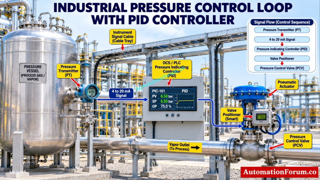
An industrial pressure control loop generally consists of a Pressure Transmitter (PT), Pressure Indicating Controller (PIC) and Pressure Control Valve (PCV).
The pressure transmitter measures the process pressure and sends a 4 to 20 mA signal to the controller. The PIC compares the measured pressure with the set point and calculates the required controller output. The PCV then adjusts its opening to maintain the required pressure.
Pressure Transmitter (PT) and 4 to 20 mA Signal Scaling
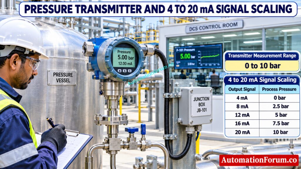
A pressure transmitter measures the pressure inside a vessel or pipeline and converts the measurement into a proportional 4 to 20 mA electrical signal.
For example, consider a pressure transmitter with a measuring range of 0 to 10 bar.
| Transmitter Output | Measured Pressure |
| 4 mA | 0 bar |
| 8 mA | 2.5 bar |
| 12 mA | 5 bar |
| 16 mA | 7.5 bar |
| 20 mA | 10 bar |
The PIC receives this signal and displays the measured pressure as its process variable.
Think You Understand PID? Prove Your Engineering Skills Now: Advanced PID Tuning Quiz for Process Industries: Test Your Industrial Process Control Expertise
Pressure Indicating Controller (PIC) and Set Point Control
The PIC compares the measured pressure with the required set point.
For example, if the pressure set point is 5 bar and the measured pressure increases to 6 bar, the controller identifies a pressure deviation and adjusts its output according to the configured PID parameters.
The controller output determines the required action of the final control element.
Direct Acting and Reverse Acting PID Controller
Controller action determines how the controller output changes when the measured pressure changes.
In direct acting configuration, the controller output increases when the measured process variable increases, assuming the same controller scaling and configuration.
In reverse acting configuration, the controller output decreases when the measured process variable increases.
The correct controller action depends on the control valve arrangement, valve fail position and process requirements. During commissioning, verify the complete loop response to ensure that the valve moves in the correct direction when pressure deviates from the set point.
Pressure Control Valve (PCV) and Final Control Element
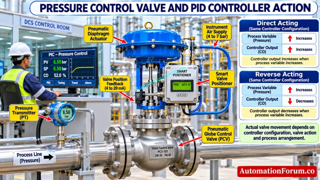
The PCV receives the controller output through a valve positioner or an appropriate I/P arrangement and adjusts its opening.
Depending on the process design, the control valve may be installed on the gas inlet, vapor outlet or another process connection.
For direct vessel pressure regulation, a vapor outlet or gas inlet control arrangement is commonly considered. A liquid outlet valve can influence vessel pressure indirectly, but it should not automatically be treated as a direct vapor pressure control arrangement.
The valve fail position, controller action and operating philosophy must be selected according to the process requirements and safety design.
Stop Confusing Automation Hardware With Essential Control Algorithms: What is the difference between PLC and PID controller?
Pressure Control Loop Signal Flow from PT to PCV
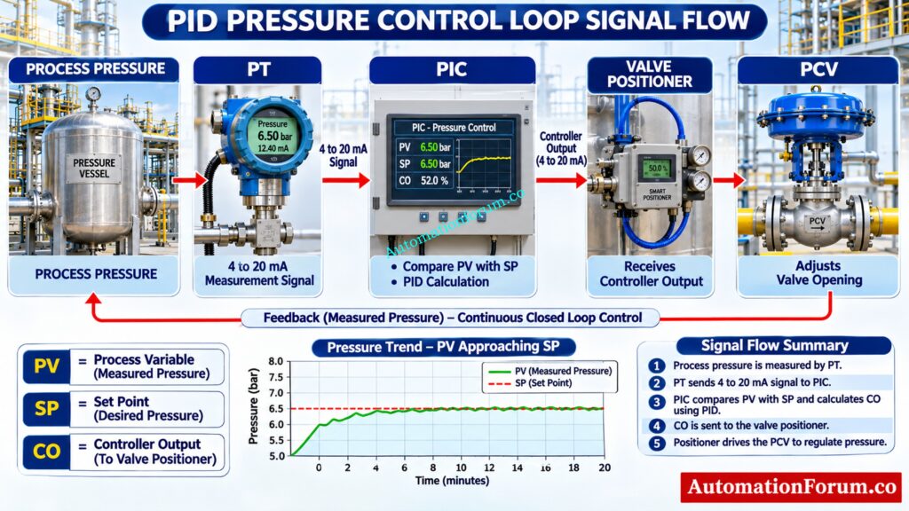
The typical pressure control signal sequence is:
Pressure Measurement → PT → 4 to 20 mA Signal → PIC → Controller Output → Valve Positioner → PCV.
The actual signal architecture depends on the selected DCS or PLC system and final control element.
Refer the below link for the Best PID Controller Tuning Simulation Tool for Engineers
PID Controller Formula and Parameters for Pressure Control
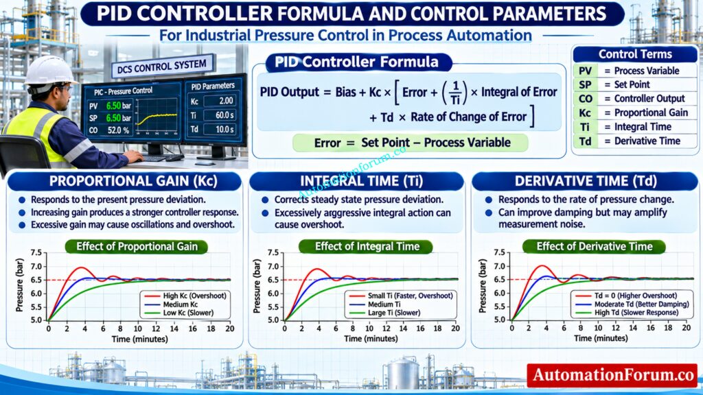
PID Control Formula for Industrial Pressure Applications
The PID controller uses three control actions: Proportional, Integral and Derivative.
The standard ideal PID controller formula is:
PID Output = Bias + Kc × [Error + (1/Ti) × Integral of Error + Td × Rate of Change of Error]
Where:
Kc = Proportional gain
Ti = Integral time in seconds
Td = Derivative time in seconds
Error = Set Point minus Process Variable
Bias = Controller output offset or reset value
The controller uses these three actions to calculate the output required to maintain the process at its set point.
In many industrial controllers, derivative action is applied to the measured process variable instead of the error. This helps prevent sudden controller output changes during set point adjustments.
The actual PID algorithm depends on the DCS or PLC configuration. Always verify the controller algorithm, parameter units and scaling before entering tuning values.
Understand Real Controller Behavior Through Practical Mechanical Applications: PID controller tuning – With motor and gear example
Proportional Gain (Kc) in Pressure Control
Proportional action responds to the difference between the set point and measured pressure.
Increasing proportional gain makes the controller respond more strongly. However, excessive gain can cause pressure fluctuations, overshoot and sustained oscillations.
Integral Time (Ti) and Pressure Deviation Correction
Integral action continuously accumulates the controller error and helps eliminate steady state pressure deviation.
A very short integral time can cause excessive controller action and pressure overshoot. A longer integral time generally produces slower correction.
Derivative Time (Td) and Pressure Response
Derivative action responds to how quickly the measured pressure changes.
It can improve damping and reduce overshoot, but excessive derivative action can amplify measurement noise. Many industrial pressure control loops operate effectively using PI control without derivative action.
In practical DCS and PLC applications, derivative action is often applied to the measured process variable rather than the controller error. This helps avoid derivative kick when the set point changes suddenly.
Avoid Costly Automation Mistakes When Selecting Output Modules: PLC Relay Output vs Transistor Output: Differences, Selection Guide and Applications
PID Tuning Methods Used in Industrial Pressure Control Systems
Ziegler Nichols Closed Loop PID Tuning Method
The Ziegler Nichols closed loop method uses two important values:
Ultimate Gain (Ku) = Proportional gain at which sustained oscillations occur.
Ultimate Period (Pu) = Time required to complete one oscillation cycle in seconds.
The classic PID tuning formulas are:
Proportional Gain:
Kc = 0.6 × Ku
Integral Time:
Ti = 0.5 × Pu
Derivative Time:
Td = 0.125 × Pu
Calculate Dangerous Pressure Surges Before Instruments Suffer Damage: Pressure Transmitter Overrange Protection Calculator: Calculate Pressure Surge and Overpressure Risk
Ziegler Nichols Open Loop PID Tuning Method
The Ziegler Nichols open loop method uses a process reaction curve obtained by applying a controlled step change to the controller output while observing the process response.
From the response curve, engineers determine the process gain, process dead time and process time constant. These values are then used to calculate the initial PID controller settings.
Kprocess = Process gain, calculated as the change in process variable divided by the change in controller output during the step test.
L = Process dead time in seconds
T = Process time constant in seconds
The controller gain formula is:
Kc = (1.2 × T) / (Kprocess × L)
Integral Time:
Ti = 2 × L
Derivative Time:
Td = 0.5 × L
These equations assume a first order process with dead time and compatible input and output scaling. The process gain must be calculated using consistent engineering units.
Find Why Automatic Operation Triggers Unexpected Valve Oscillations: Why Control Valve Hunts in AUTO but Runs Smoothly in MANUAL
Tyreus Luyben PID Tuning Method
The Tyreus Luyben method provides an alternative closed loop tuning approach. It generally produces less aggressive settings than classic Ziegler Nichols tuning.
For PID control, the formulas are:
Proportional Gain:
Kc = Ku / 2.2
Integral Time:
Ti = 2.2 × Pu
Derivative Time:
Td = Pu / 6.3
The proportional gain of 0.31 × Ku sometimes shown in tuning tables belongs to the Tyreus Luyben PI tuning rule, not its PID rule.
For applications requiring more robust control, Internal Model Control (IMC) and other model based tuning methods can also be considered.
Refer the below link for the PID controller tuning methods
Step by Step PID Tuning Procedure for Pressure Controllers
The following procedure explains how to perform PID tuning during an approved commissioning or maintenance activity.
- Verify pressure transmitter calibration and measurement range.
- Check the pressure control valve, actuator and positioner operation.
- Confirm controller configuration and direct or reverse acting control.
- Establish stable and suitable process operating conditions.
- Use proportional only control for the selected ultimate gain method.
- Determine ultimate gain and oscillation period if the approved test permits.
- Calculate the required PID parameters.
- Enter the calculated values into the PIC or DCS.
- Monitor pressure response and make controlled adjustments.
Uncover Mechanical Problems That Destroy Accurate Valve Positioning: Top Common Causes of Hysteresis in Control Valve in Process Plants
Ziegler Nichols PID Tuning Calculation with Practical Example
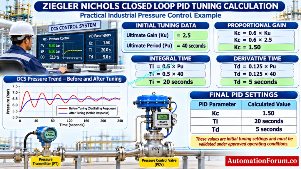
Consider the following values obtained during an approved Ziegler Nichols closed loop tuning test.
Ultimate Gain (Ku) = 2.5
Ultimate Period (Pu) = 40 seconds
Incorrect Actuator Settings Can Ruin Your Control Performance: Why is Control Valve Actuator Bench Set Important ?
Calculate Proportional Gain Using Ultimate Gain
Formula:
Kc = 0.6 × Ku
Substitute the values:
Kc = 0.6 × 2.5
Kc = 1.50
Calculate Integral Time Using Ultimate Period
Formula:
Ti = 0.5 × Pu
Substitute the values:
Ti = 0.5 × 40
Ti = 20 seconds
Calculate Derivative Time Using Ultimate Period
Formula:
Td = 0.125 × Pu
Substitute the values:
Td = 0.125 × 40
Td = 5 seconds
Solve Persistent Actuator Problems Before They Affect Production: Common Challenges and Solutions for Industrial Control Valve Actuators
Final PID Controller Settings for Pressure Control
| PID Parameter | Calculated Value |
| Proportional Gain (Kc) | 1.50 |
| Integral Time (Ti) | 20 seconds |
| Derivative Time (Td) | 5 seconds |
These are initial tuning values and are not guaranteed final operating settings.
For a DCS using the ideal PID algorithm with gain and time settings, enter Kc as 1.50, Ti as 20 seconds and Td as 5 seconds.
If the controller uses proportional band instead of proportional gain, the equivalent proportional band is:
PB = 100 / Kc
PB = 100 / 1.50
PB = 66.67%
This proportional band conversion assumes a normalized controller gain based on percentage input and output scaling. Actual proportional band configuration may vary depending on the DCS or PLC controller algorithm. Always verify the manufacturer’s controller documentation before entering the calculated value.
Never Ignore Abnormal Current Signals During Pressure Measurement: Why Is My Pressure Transmitter Showing 22 mA? Complete Troubleshooting Guide for Instrument Engineers
Industrial Applications of PID Pressure Control in Process Plants
PID tuning is important in several process automation applications.
- Pressure Vessel Control: Maintains vapor space pressure within the required operating range.
- Reactor Pressure Control: Regulates pressure during chemical processing.
- Compressor Discharge Pressure Control: Maintains the required compressor discharge pressure.
- Steam Header Pressure Control: Balances steam supply and downstream demand.
- Gas Distribution Systems: Maintains stable pressure across distribution networks.
- Filter and Pipeline Pressure Control: Controls pressure during filtration and fluid transportation.
- Backpressure Control: Maintains upstream pressure by regulating downstream flow.
Vessel volume, process dead time, valve characteristics, process gain, measurement noise and operating conditions influence the final PID tuning parameters.
Two Pressure Readings Disagree? Identify the Actual Problem: Pressure Gauge vs Pressure Transmitter: When Readings Don’t Match, Who Should You Trust?
Pressure Control Loop Troubleshooting and PID Tuning Problems
| Problem | Possible Cause and Engineering Check |
| Continuous pressure fluctuations | Excessive controller gain, aggressive integral action or process disturbances. Review PID settings and process trends. |
| Pressure overshoot | Excessive integral action or unsuitable tuning. Check integral time and controller response. |
| Slow pressure response | Low proportional gain or excessive integral time. Review process dynamics. |
| Control valve hunting | Poor tuning, positioner problems, stiction or incorrect valve sizing. |
| Transmitter signal fluctuations | Electrical interference, impulse line problems or unstable process pressure. |
| Controller output saturation | Valve capacity limitation or insufficient actuator authority. Check output limits. |
| Integral windup | Integral action continues during output saturation. Verify anti windup configuration. |
| Incorrect controller action | Incorrect direct or reverse acting configuration. Verify the complete loop response. |
| Valve stiction and deadband | Mechanical friction, actuator problems or positioner issues. Inspect valve performance. |
| Incorrect PID configuration | Wrong algorithm, units, proportional band or integral time settings. Verify controller documentation. |
Prevent Dangerous Measurement Errors During Boiler Drum Commissioning: Commissioning Procedure for Differential Pressure Transmitters in Pressurized Boiler Steam Drums
Best Practices for PID Tuning During Plant Commissioning
Before finalizing PID tuning, instrumentation and control engineers should verify the following points:
- Complete pressure transmitter calibration and loop checking.
- Confirm correct control valve sizing and characteristics.
- Verify controller action and signal direction.
- Configure anti windup protection.
- Apply suitable derivative filtering where required.
- Establish appropriate controller output and rate limits.
- Evaluate normal operating conditions and process disturbances.
- Verify coordination with alarms and independent protection systems.
- Record final PID parameters and the tuning methodology.
- Monitor controller performance after commissioning.
Normal PID tuning must remain separate from safety instrumented functions. Never change safety trip settings as part of routine pressure controller tuning.
Avoid Incorrect Connections During Critical Instrument Calibration Work: Wiring Diagram for Pressure Transmitter Calibration in Workbench using HART
Frequently Asked Questions About PID Tuning for Pressure Control
What Is the Best PID Tuning Method for Pressure Control?
The best tuning method depends on process dynamics, pressure stability requirements and operating conditions. IMC and Ziegler Nichols are commonly considered, but Ziegler Nichols can produce an aggressive response.
How Do You Calculate PID Parameters Using Ziegler Nichols?
First, determine the ultimate gain (Ku) and ultimate period (Pu) through an approved tuning test. Calculate Kc = 0.6 × Ku, Ti = 0.5 × Pu and Td = 0.125 × Pu.
Never Miss These Essential Checks Before Plant Startup: Pressure Transmitter Commissioning Checklist
What Is Ultimate Gain in PID Tuning?
Ultimate gain (Ku) is the proportional gain at which the control loop produces continuous, sustained oscillations. It is used to calculate the initial PID controller settings using the Ziegler Nichols closed loop method.
What Is the Ultimate Period in Pressure Control?
Ultimate period (Pu) is the time taken to complete one full cycle of sustained pressure oscillation. It is measured in seconds and used to calculate the integral and derivative times.
What Happens When Proportional Gain Is Too High?
When proportional gain is too high, the controller reacts excessively to small pressure deviations. This can result in pressure fluctuations, overshoot and continuous control valve movement.
Why Does a Pressure Control Valve Continuously Hunt?
Continuous valve hunting can result from aggressive PID settings, valve stiction, positioner problems or unstable transmitter signals. Check the controller output trend and actual valve position before changing the tuning parameters.
Should Derivative Action Be Used in Pressure Control?
Derivative action can improve damping when pressure changes rapidly and the process benefits from predictive control. However, it can amplify measurement noise, so PI control is often sufficient for many pressure applications.
How Often Should PID Tuning Be Checked in Process Plants?
Check PID performance during commissioning and whenever process conditions, equipment or control valve characteristics change. Regularly reviewing pressure trends helps identify problems that may require retuning.
Discover Critical Leakage Problems Before They Become Expensive: Control Valve Leakage Testing, Types, and Calculation Standards
What Is PID Tuning?
PID tuning is the process of adjusting proportional, integral and derivative parameters to achieve stable process control. Proper tuning helps maintain the required set point while minimizing overshoot and unwanted process fluctuations.
How Do You Tune a PID System?
Start by checking the transmitter, controller configuration and control valve operation before adjusting any parameters. Apply an approved tuning method, calculate the PID settings and verify the process response under controlled operating conditions.
What Is the Difference Between PID Tuning and Instrument Calibration?
Instrument calibration verifies the accuracy of the pressure transmitter, while PID tuning adjusts controller parameters to achieve stable process control. Both activities are important during commissioning, but they serve different engineering purposes.
What Are the Tuning Parameters of a PID Controller?
The three main PID tuning parameters are proportional gain (Kc), integral time (Ti) and derivative time (Td). They determine how strongly and how quickly the controller responds to process errors.
Identify the Real Reasons Behind Repeated Valve Oscillations: What are the main causes of control valve hunting?
What Are the Common PID Controller Algorithm Forms?
Common PID algorithm forms include ideal, parallel and series configurations. Their parameter definitions and tuning values can differ depending on the controller implementation.
What Is the Difference Between PI and PID Control?
PI control uses proportional and integral actions to maintain the required process set point. PID control includes an additional derivative action to improve damping and response where required.
Never Miss These Essential Checks Before Plant Startup: Pressure Transmitter Commissioning Checklist
Conclusion: Achieving Stable Pressure Control Through Proper PID Tuning
Proper PID tuning for pressure control is essential for stable process operation, reliable control valve performance and consistent pressure regulation.
Instrumentation and control engineers should verify the pressure transmitter, controller configuration, control valve characteristics and process dynamics before changing PID parameters. Calculated tuning settings must always be validated under approved operating conditions before being accepted as final plant settings.
Refer the below link for the Control Valve Hunting Due to PID Controller: Causes, Effects, Root Analysis and Complete Troubleshooting
