
- What Is an RFI or Inspection Request in Instrumentation Projects?
- Why is an RFI Important in Instrumentation and Control Projects?
- RFI Inspection Request Procedure and Workflow
- What Happens When an Instrumentation RFI Is Rejected?
- RFI Acceptance, Closure and QA/QC Documentation
- Practical Instrumentation RFI Example: Pressure Transmitter Installation
- RFI Checklist for Instrumentation and E&I QA/QC
- Final Instrumentation RFI Readiness Check
- Common Instrumentation RFI Mistakes That Cause Inspection Rejection
- RFI vs ITP vs Method Statement vs Inspection Checklist
- Best Practices for E&I RFI Management in EPC Projects
- Instrumentation RFI Troubleshooting and Site Scenarios
- Frequently Asked Questions About Instrumentation RFI and QA/QC
- Conclusion: RFI Inspection Request Procedure for Instrumentation Projects
A Request for Inspection, commonly called an RFI, is not simply a form submitted to the client when construction work is completed. In a well controlled EPC project, an RFI is the formal quality control step that connects completed construction work with approved engineering documents, the Inspection and Test Plan, internal QA/QC verification, client inspection and final quality records.
The basic sequence is simple: complete the work, verify the work internally, confirm the applicable documents and inspection requirements, raise the RFI, conduct the required inspection, record the result and close the inspection record. The practical value comes from how carefully each stage is controlled. Pasted markdown
An RFI raised before the work is genuinely ready can result in rejected inspections, repeated client visits, rework and loss of confidence in the contractor.
What Is an RFI or Inspection Request in Instrumentation Projects?
What Is an RFI in QA/QC?
An RFI is a formal notification to the designated inspecting party that a defined item of work has been completed and is ready for inspection or verification according to approved project requirements.
How Does an RFI Provide Instrumentation Quality Traceability?
The exact RFI process depends on the project specification, contract, client procedure and approved ITP. However, the underlying purpose remains the same: provide a controlled opportunity to verify that the completed work satisfies the applicable requirements and that objective inspection evidence is generated.
In practical EPC execution, an RFI connects construction completion with quality acceptance.
Why is an RFI Important in Instrumentation and Control Projects?
Instrumentation work contains many details that may become difficult or expensive to correct after subsequent activities are completed.
An RFI may be required for activities such as instrument installation, cable installation, cable termination, junction box installation, instrument tubing, impulse tubing, control valve installation, instrument calibration, instrument air installation, earthing, panel installation, marshalling cabinet installation and testing.
For example, an incorrectly installed pressure transmitter may appear acceptable visually but could have an incorrect tag, wrong orientation, unsuitable accessibility, incorrect impulse tubing arrangement or missing calibration documentation.
The RFI process provides traceability between the installed equipment, approvedengineering documents, inspection results and final QA/QC dossier.
Refer the below link for the Vendor Document for Project Systems Architecture: Complete Engineering Guide for Instrumentation, Automation and Control
RFI Inspection Request Procedure and Workflow
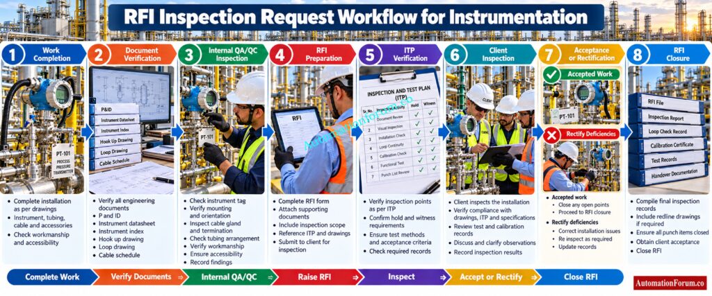
A practical RFI workflow normally follows this sequence:
Work completion → Document verification → Internal QA/QC inspection → RFI preparation → ITP inspection point verification → Client inspection → Acceptance or rectification → RFI closure → QA/QC dossier update
The important point is that the RFI should come after technical readiness, not before it.
Step 1: Verify Instrumentation Work Readiness
The QA/QC inspector should first confirm that the work is actually complete.
Check the approved drawing, instrument tag, material, installation location, accessibility, installation condition, cable and tubing installation, termination, labelling, identification, workmanship and housekeeping.
Confirm that prerequisite activities are complete. If calibration is required, verify that the applicable calibration record is available. If testing is required before inspection, confirm that the required test has been completed and recorded.
Construction pressure should never be the reason for raising an RFI. The correct question is whether the work can withstand a detailed technical inspection.
Select the correct cable gland before installation begins: Instrument Cable Gland Selector Calculator Guide
Step 2: Verify Approved Engineering Documents
Document control is one of the most important parts of RFI preparation.
The inspector should verify the latest approved revision of applicable documents such as:
| Document | Typical verification |
| IFC drawing | Correct revision and installation details |
| P and ID | Correct instrument identification and process connection |
| Instrument datasheet | Range, service and equipment details |
| Instrument index | Tag and service confirmation |
| Cable schedule | Cable number and routing information |
| Hook up drawing | Mounting and tubing arrangement |
| Loop drawing | Signal and connection details |
| Junction box drawing | Termination and cable information |
| Wiring drawing | Correct electrical connection |
| Installation specification | Applicable workmanship requirements |
| Method Statement | Approved installation procedure |
| ITP | Inspection point and acceptance requirements |
| Calibration certificate | Calibration status and traceability |
| Test records | Required testing evidence |

Using a superseded drawing can create a serious inspection problem because theinstallation may appear correct against an old revision while being incorrect against the current approved design.
Verify field instruments thoroughly before raising your RFI: Checklist for Installation of Local Instruments – Complete Guide for EPC, QA/QC and Commissioning
Step 3: Perform Internal Instrumentation QA/QC Inspection

Internal inspection should happen before the client or consultant is invited.
For an instrumentation installation, the inspector should verify the tag number, nameplate, mounting arrangement, orientation, accessibility, cable routing, cable gland, termination, tubing, tube supports, earthing, calibration status, continuity and workmanship.
The inspection should also confirm that the physical installation agrees with the approved engineering documents.
This internal inspection is where many potential client comments should be identified and corrected. A strong QA/QC team does not use the client inspection as the first detailed inspection of the work.
Choose compliant Ex zone cables before field installation: What Cables to Use in Ex Zones: Complete Guide for Instrumentation & Control Engineers
Step 4: Prepare the Instrumentation RFI
The RFI should contain enough information for the inspecting party to understand exactly what is ready for inspection.
Typical information includes project, area, system, subsystem, location, tag number, activity description, drawing reference, specification reference, ITP reference, inspection checklist, inspection date, inspection point and supporting documents.
The contractor QA/QC representative should also be identified according to the project procedure.
Incorrect tag numbers, locations or drawing references can create unnecessary delays even when the physical installation is satisfactory.
Improve industrial signal reliability with proper cable selection: Twisted Pair Cable in Industrial Signal Transmission: The Essential Guide for 4-20 mA
Step 5: Verify ITP Inspection Points
The Inspection and Test Plan establishes what is inspected, when it is inspected, who participates and what evidence is retained. Current industry guidance similarly describes the ITP as the document that connects inspection activities, acceptance criteria, responsibilities and quality records.
Hold Point
Witness Point
A Witness Point gives the designated party an opportunity to witness an inspection or test. Whether work may proceed without attendance depends on the approved ITP and project procedure.
Review Point
A Review Point generally involves review of documents, records, certificates or other evidence. It should not automatically be treated as a physical inspection or release unless the project documents define it that way.
Surveillance Point
A Surveillance Point allows the designated party to monitor work during execution. It is normally associated with ongoing observation rather than a single formal inspection event.
These definitions can vary between projects, so the approved ITP and contract requirements always take precedence.
Trace instrument signals correctly before starting loop checks: Instrument Loop Diagrams
Step 6: Conduct Client or Consultant Inspection
During client inspection, the contractor should present the completed work, approved drawings, inspection checklist and applicable test records.
The inspector may verify the physical installation, compare it with drawings, examine equipment identification, review supporting records and request demonstrations or additional checks.
Being physically present with completed equipment is not the same as being inspection ready. The contractor should be able to explain what was installed, which requirement applies, how it was verified and where the supporting evidence is recorded.
Fix shutdown documentation gaps before safety reviews begin: Shutdown Philosophy: Engineering Documentation for Process Safety and Emergency Shutdown Systems

What Happens When an Instrumentation RFI Is Rejected?
An RFI rejection should be treated as a technical quality issue rather than simply changing an administrative status.
The normal process is to identify the issue, determine the applicable requirement, correct the work, verify the correction internally and arrange reinspection according to the project procedure.
An NCR may be required when the condition meets the project’s nonconformance criteria.
For example, suppose a pressure transmitter has been installed with an incorrect tag. The contractor should correct the identification, verify the tag against the approved instrument index and drawing, confirm that associated records are also correct and then request reinspection.
The same principle applies to incorrect cable termination, missing glands, incorrect tubing connections, missing calibration records, wrong installation orientation or incomplete testing.
Stop incorrect shield grounding from causing signal problems: Where Should You Terminate Cable Shields in Instrumentation and Control Systems?
RFI Acceptance, Closure and QA/QC Documentation
After successful inspection, the required acceptance, signatures and status updates should be completed.
The inspection checklist, test records, punch information and supporting documents should be linked to the RFI. The closed RFI should then be filed within the project QA/QC records.
These records eventually contribute to the final quality dossier and handover documentation.
A closed RFI therefore provides more than evidence that someone inspected the work. It provides traceability showing what was inspected, against which requirement, when it was inspected and what evidence supported acceptance.
Practical Instrumentation RFI Example: Pressure Transmitter Installation
Consider an RFI for a newly installed pressure transmitter.
First, construction completes the mounting, process connection, impulse tubing and cable connection.
The QA/QC inspector verifies the transmitter tag against the instrument index and approved drawing. The datasheet is checked for service and range. The mounting arrangement and accessibility are inspected. The impulse tubing and manifold arrangement are compared with the approved hook up drawing.
The cable number and termination are checked against the cable schedule and loop drawing. The calibration certificate is verified. The applicable ITP inspection point is then confirmed.
After internal QA/QC inspection is satisfactory, the RFI is prepared with the correct tag, location, drawing references, ITP reference and supporting records.
The client inspects the installation. If accepted, the inspection record is signed and closed. If a problem is found, it is corrected and internally verified before reinspection.
This is how an RFI becomes part of the engineering quality control process rather than simply becoming another document in the project file.
Prevent PLC trip documentation errors before commissioning: PLC Alarm and Trip Documentation Procedure – EPC PLC Automation Engineer Guide
RFI Checklist for Instrumentation and E&I QA/QC
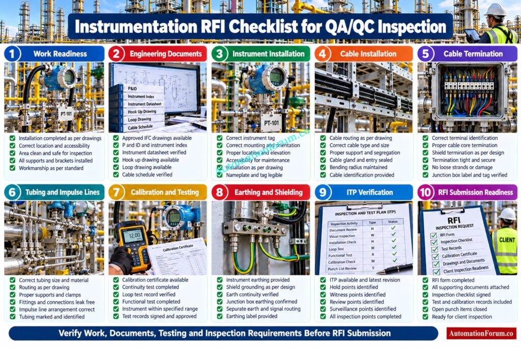
Before submitting an RFI, the QA/QC inspector should verify the complete physical installation, engineering documentation, testing status, inspection requirements and supporting records. The following detailed checklist can be used as a practical pre inspection readiness check.
| Inspection Category | Detailed Verification Point | What the QA/QC Inspector Should Check | Typical Evidence or Reference | Status |
| Work Readiness | Work completely installed | Confirm that the defined instrumentation or E&I scope is physically complete and no major installation activity remains outstanding. | Approved drawing, construction completion record | Confirm |
| Work Readiness | Installation ready for inspection | Ensure the equipment is physically accessible and can be inspected without additional construction work. | Site inspection | Confirm |
| Work Readiness | Previous activities completed | Verify that all prerequisite construction, mechanical or electrical activities required before the inspection are complete. | Approved ITP and work sequence | Confirm |
| Engineering Documents | Latest approved drawing | Confirm that the installation has been executed using the latest approved drawing revision. | IFC drawing | Confirm |
| Engineering Documents | Drawing revision | Check that the drawing revision mentioned in the RFI matches the current approved revision. | Document control system | Confirm |
| Engineering Documents | Instrument index | Verify the instrument tag, service and location against the approved instrument index. | Instrument index | Confirm |
| Engineering Documents | Instrument datasheet | Confirm instrument type, range, process connection and other applicable details. | Instrument datasheet | Confirm |
| Engineering Documents | P and ID | Verify the instrument identification and process connection against the approved P and ID. | Approved P and ID | Confirm |
| Engineering Documents | Hook up drawing | Verify mounting, tubing, manifold, fittings and installation arrangement. | Approved hook up drawing | Confirm |
| Engineering Documents | Loop drawing | Confirm signal wiring, terminals and loop connections where applicable. | Approved loop drawing | Confirm |
| Engineering Documents | Cable schedule | Verify cable number, source, destination and applicable cable information. | Approved cable schedule | Confirm |
| Engineering Documents | Termination drawing | Confirm that field and panel terminations match the approved termination details. | Termination drawing | Confirm |
| Engineering Documents | Junction box drawing | Verify junction box identification, terminals, cable entries and connections. | Junction box drawing | Confirm |
| Material Verification | Instrument model | Confirm that the installed instrument matches the approved equipment specification. | Datasheet and material record | Confirm |
| Material Verification | Material identification | Verify equipment identification and applicable material requirements. | Material documentation | Confirm |
| Material Verification | Nameplate | Check instrument nameplate details against the approved datasheet and tag. | Physical inspection | Confirm |
| Material Verification | Certificates | Verify applicable material, conformity or manufacturer documentation where required. | Approved certificates | Confirm |
| Instrument Installation | Instrument tag | Confirm that the physical tag matches the approved instrument index and drawings. | Instrument index and field inspection | Confirm |
| Instrument Installation | Installation location | Verify that the instrument is installed at the correct location shown in the approved engineering documents. | Layout drawing and field inspection | Confirm |
| Instrument Installation | Mounting arrangement | Check mounting supports, brackets, bolts and mechanical stability. | Hook up drawing and site inspection | Confirm |
| Instrument Installation | Orientation | Verify that the instrument orientation is suitable for the application and matches the approved installation arrangement. | Hook up drawing and manufacturer information | Confirm |
| Instrument Installation | Accessibility | Confirm that the instrument can be safely accessed for operation, calibration and maintenance. | Site inspection | Confirm |
| Instrument Installation | Environmental protection | Check that the installation provides the required protection from the surrounding process environment. | Project specification and site inspection | Confirm |
| Cable Installation | Cable identification | Verify cable number and identification against the cable schedule. | Cable schedule | Confirm |
| Cable Installation | Cable routing | Check that cable routing follows the approved route and applicable installation requirements. | Cable routing drawing and site inspection | Confirm |
| Cable Installation | Cable support | Verify that cables are properly supported and mechanically protected. | Installation specification | Confirm |
| Cable Installation | Cable gland | Confirm correct gland type, size, installation and tightening. | Cable schedule and installation specification | Confirm |
| Cable Installation | Cable entry | Verify that cable entry into the instrument or junction box is correct and properly sealed. | Site inspection | Confirm |
| Cable Termination | Terminal identification | Confirm field terminals match the approved termination drawing. | Termination drawing | Confirm |
| Cable Termination | Core identification | Verify individual cable cores and wire numbers. | Wiring and termination drawing | Confirm |
| Cable Termination | Termination quality | Check that terminals are secure, correctly terminated and free from visible workmanship defects. | Visual inspection | Confirm |
| Cable Termination | Shield connection | Verify shield termination according to the approved project philosophy. | Wiring diagram and project specification | Confirm |
| Tubing Installation | Tubing size | Confirm tubing size and material against the approved hook up drawing and specification. | Hook up drawing | Confirm |
| Tubing Installation | Tubing routing | Check tubing routing, support and protection from mechanical damage. | Site inspection | Confirm |
| Tubing Installation | Tube support | Verify adequate support and acceptable installation arrangement. | Installation specification | Confirm |
| Tubing Installation | Fittings | Check tube fittings, connections and mechanical integrity. | Hook up drawing and visual inspection | Confirm |
| Impulse Tubing | Impulse line arrangement | Verify impulse tubing arrangement against the approved hook up drawing. | Hook up drawing | Confirm |
| Impulse Tubing | Slope | Where applicable, verify that impulse lines have the required slope for the measurement service. | Project specification and hook up drawing | Confirm |
| Impulse Tubing | Connection integrity | Check all connections for correct assembly and visible leakage or workmanship concerns. | Visual inspection and applicable test record | Confirm |
| Control Valve | Valve identification | Verify valve tag, size and specification against approved documents. | Valve datasheet and P and ID | Confirm |
| Control Valve | Actuator installation | Verify actuator mounting, orientation and mechanical arrangement. | Approved drawing and manufacturer information | Confirm |
| Control Valve | Positioner | Confirm positioner installation, tubing and signal connection. | Hook up and loop drawings | Confirm |
| Control Valve | Accessories | Verify solenoid valves, air filter regulator and other applicable accessories. | Valve datasheet and hook up drawing | Confirm |
| Calibration | Calibration status | Confirm that required instruments have been calibrated before inspection where applicable. | Calibration certificate | Confirm |
| Calibration | Calibration range | Verify that the calibration range corresponds with the approved instrument requirements. | Datasheet and calibration certificate | Confirm |
| Calibration | Calibration result | Check that recorded calibration results satisfy the applicable project acceptance requirements. | Calibration certificate | Confirm |
| Calibration | Certificate traceability | Verify instrument tag, serial number and calibration identification. | Calibration certificate | Confirm |
| Testing | Continuity test | Confirm required continuity testing has been completed where applicable. | Continuity test record | Confirm |
| Testing | Insulation testing | Verify applicable insulation testing has been completed and recorded according to project requirements. | Test record | Confirm |
| Testing | Loop testing | Confirm required loop testing has been completed where the inspection stage requires it. | Loop test record | Confirm |
| Testing | Functional testing | Verify required functional tests have been completed. | Functional test record | Confirm |
| Testing | Instrument response | Confirm instrument response is satisfactory where functional verification is applicable. | Test record | Confirm |
| Earthing | Instrument earthing | Verify required instrument earthing connections. | Earthing drawing and site inspection | Confirm |
| Earthing | Cable shield grounding | Confirm shield grounding arrangement according to the approved project philosophy. | Wiring diagram | Confirm |
| Earthing | Panel or junction box earthing | Verify applicable protective earthing connections. | Electrical drawing and site inspection | Confirm |
| ITP Verification | Applicable ITP | Confirm that the correct approved ITP applies to the activity. | Approved ITP | Confirm |
| ITP Verification | Inspection point | Identify whether the activity is subject to Hold Point, Witness Point, Review Point or Surveillance Point requirements. | Approved ITP | Confirm |
| ITP Verification | Acceptance criteria | Verify that the inspection will be performed against the applicable acceptance requirements. | ITP and specification | Confirm |
| Inspection Checklist | Checklist availability | Confirm that the correct approved inspection checklist is available. | Approved checklist | Confirm |
| Inspection Checklist | Checklist completion | Complete all applicable inspection points before requesting client inspection. | Inspection checklist | Confirm |
| Inspection Checklist | Inspector verification | Ensure required internal inspection signatures or approvals are completed according to project procedure. | QA/QC inspection record | Confirm |
| Supporting Documents | Calibration certificates | Attach required calibration certificates. | Calibration records | Confirm |
| Supporting Documents | Test records | Attach applicable test and verification records. | Test documentation | Confirm |
| Supporting Documents | Material records | Provide applicable material or equipment documentation where required. | Material documentation | Confirm |
| Supporting Documents | Previous inspection records | Verify relevant previous inspection or prerequisite records where applicable. | QA/QC records | Confirm |
| RFI Details | Project information | Confirm project name, area and system information. | RFI form | Confirm |
| RFI Details | Instrument tag | Verify the exact field tag number. | RFI and instrument index | Confirm |
| RFI Details | Location | Confirm the physical location matches the RFI description. | RFI and site inspection | Confirm |
| RFI Details | Activity description | Clearly describe the specific work being offered for inspection. | RFI form | Confirm |
| RFI Details | Drawing reference | Enter the correct approved drawing number and revision. | RFI and document register | Confirm |
| RFI Details | ITP reference | Enter the applicable ITP reference and inspection point. | Approved ITP | Confirm |
| Site Condition | Accessibility | Ensure the client inspector can safely access the equipment. | Site inspection | Confirm |
| Site Condition | Housekeeping | Confirm that the inspection area is clean and free from unnecessary materials or obstruction. | Site inspection | Confirm |
| Site Condition | Identification | Ensure instrument and equipment identification is clearly visible. | Field inspection | Confirm |
| Site Condition | Safety readiness | Confirm that the inspection can be conducted under the applicable site safety requirements. | Project safety procedure | Confirm |
| Internal QA/QC | Internal inspection completed | Confirm that the contractor QA/QC inspector has already inspected the work. | Internal inspection record | Confirm |
| Internal QA/QC | Deficiencies corrected | Verify that identified construction deficiencies have been corrected before RFI submission. | Punch or observation record | Confirm |
| Internal QA/QC | Documentation reconciled | Confirm physical installation and engineering documentation are consistent. | Drawings, index and field inspection | Confirm |
| Final RFI Readiness | Client inspection readiness | Confirm that the complete inspection package is ready before inviting the client or consultant. | RFI package | Confirm |
| Final RFI Readiness | No open critical issues | Verify that no unresolved issue can reasonably prevent acceptance. | Punch and observation records | Confirm |
| Final RFI Readiness | RFI submitted correctly | Confirm all required RFI fields and attachments are complete before submission. | Completed RFI | Confirm |
Verify critical alarm settings before plant startup: Alarm & Trip Setpoint List in Instrumentation Engineering
Final Instrumentation RFI Readiness Check
Before submitting the RFI, the QA/QC inspector should be able to answer yes to the following questions:
| Final Question | Required Condition | Status |
| Is the instrumentation work physically complete? | No outstanding construction activity within the inspection scope | Confirm |
| Is the latest approved engineering documentation available? | Correct revision verified | Confirm |
| Is the instrument tag correct? | Field tag matches approved project documentation | Confirm |
| Has internal QA/QC inspection been completed? | Installation already checked by contractor QA/QC | Confirm |
| Are calibration records available? | Required calibration evidence is complete and traceable | Confirm |
| Are required tests complete? | Applicable testing has been completed and recorded | Confirm |
| Is the applicable ITP point identified? | Correct inspection point confirmed | Confirm |
| Is the inspection checklist complete? | All applicable checks have been performed | Confirm |
| Are supporting documents ready? | Required records are available for inspection | Confirm |
| Is the installation accessible? | Client or consultant can inspect the work safely | Confirm |
| Is the area clean and properly identified? | Housekeeping and equipment identification are satisfactory | Confirm |
| Is the RFI information accurate? | Tag, location, drawing and ITP references are correct | Confirm |
The key principle is simple: an RFI should be submitted only when the work, documentation and inspection evidence are all ready for formal verification. This is the practical quality control approach emphasized in the source prompt, where work readiness, document verification, internal QA/QC inspection and ITP compliance are treated as prerequisites to client inspection.
Protect your PLC records before final project handover: PLC System Documentation Guide: Essential Records for Industrial Automation
Common Instrumentation RFI Mistakes That Cause Inspection Rejection
Raising an RFI before work completion can cause immediate rejection.
Using superseded drawings can result in technically incorrect acceptance decisions.
Missing calibration certificates or test records can prevent acceptance even when the physical installation appears correct.
Calling the client before internal inspection wastes inspection time and increases repeated visits.
Ignoring ITP inspection points can create a serious procedural nonconformance.
Poor housekeeping, inaccessible equipment and incomplete documentation also make the installation appear unprepared for formal inspection.
The best approach is simple: correct the work and documentation before inviting the client.
Discover the engineering documents successful projects cannot ignore: 82 Essential Drawings and Documents for Instrumentation and Control Engineers
RFI vs ITP vs Method Statement vs Inspection Checklist
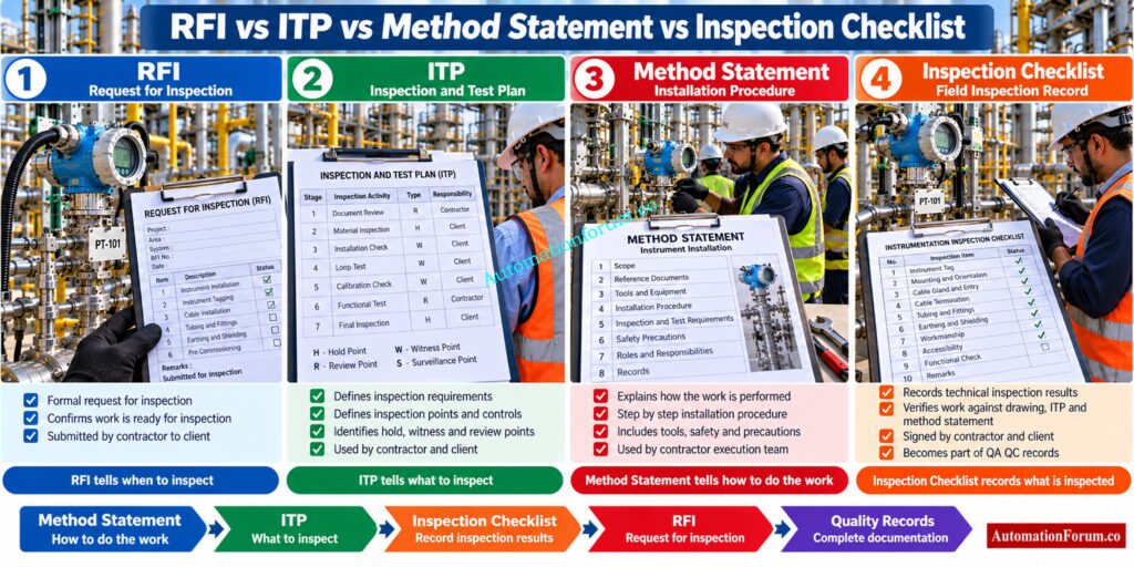
| Document | Primary purpose |
| Method Statement | Explains how the work will be performed |
| ITP | Defines what is inspected, when it is inspected and applicable inspection controls |
| RFI | Formally notifies the designated party that defined work is ready for inspection |
| Inspection Checklist | Records the checks performed and their results |
These documents work together. One does not replace another.
Download practical templates and eliminate documentation delays: Downloadable Engineering Documentation Instrumentation and Control Templates
Best Practices for E&I RFI Management in EPC Projects
Strong RFI management starts before the inspection request is created.
Maintain strict drawing revision control. Use accurate instrument tag information. Link RFIs to the applicable ITP and inspection checklist. Maintain clear supporting records and ensure inspection areas remain accessible.
Digital RFI systems can improve status tracking, document attachment, inspection scheduling and traceability when properly configured.
Most importantly, construction, engineering and QA/QC should communicate before an RFI is submitted. Many rejected inspections are not caused by difficult technical requirements. They are caused by poor coordination, incomplete documentation or insufficient readiness.
Refer the below link for the Types of Engineering Drawings and Documents used in Instrumentation
Instrumentation RFI Troubleshooting and Site Scenarios
Scenario 1: Calibration Certificate Missing Before RFI
Scenario 2: Instrument Tag Does Not Match the Drawing
The inspection should be stopped and the discrepancy investigated. The tag, instrument index, drawing and physical installation must be reconciled before acceptance.
Scenario 3: Cable Termination Does Not Match the Approved Drawing
The incorrect termination should be rectified, followed by internal verification against the approved termination drawing. Reinspection should only be requested after the correction is confirmed.
Catch signal mismatches before they disrupt commissioning: Loop Checking Field vs Control Room Reading Mismatch Explained
Frequently Asked Questions About Instrumentation RFI and QA/QC
What is an RFI request for instrumentation inspection?
An instrumentation RFI formally notifies the client or consultant that defined E&I work is ready for inspection.
It provides traceability between the completed installation, approved documents, inspection results and acceptance.
What is the RFI procedure in instrumentation and control projects?
The typical procedure includes work completion, document verification, internal QA/QC inspection, RFI submission, client inspection, rectification and closure.
The exact process depends on the approved project procedure, ITP, contract and client requirements.
What are the seven steps in an instrumentation inspection process?
The seven practical steps are work completion, document verification, internal inspection, RFI preparation, client inspection, rectification or acceptance and RFI closure.
These steps help control installation quality and maintain proper inspection traceability.
Generate accurate instrument indexes faster from P and IDs: Comparison of Top Automated Tools for Instrument Index Generation from P&IDs in EPC Engineering
What is a QA/QC checklist for instrumentation work?
An instrumentation QA/QC checklist records the required checks for installation, identification, workmanship, testing, calibration and documentation.
It helps the inspector confirm that the work satisfies the applicable project requirements before RFI submission.
What is an RFI in E&I QA/QC?
An RFI in E&I QA/QC is a formal request for inspection of completed electrical and instrumentation work.
It allows the designated inspecting party to verify the work against approved drawings, specifications, ITP requirements and supporting records.
What is an RFI procedure for instrumentation installation?
The procedure normally starts with installation completion and internal verification before the contractor submits the inspection request.
Client inspection, acceptance or rectification is then recorded and the approved RFI becomes part of the project quality documentation.
When should an instrumentation RFI be raised?
An RFI should be raised after the defined instrumentation activity is complete and internally verified.
Required drawings, checklists, calibration records, test results and other supporting documents should be available when required.
What information should an instrumentation RFI contain?
An instrumentation RFI normally includes the project, area, location, instrument tag, activity description, drawing reference and applicable ITP inspection point.
Supporting checklists, calibration certificates, test records and other required documents should also be included.
What is the difference between an RFI and an ITP for instrumentation?
The ITP defines the inspection and testing requirements, inspection points and applicable quality controls for the work.
The RFI formally requests inspection when the defined instrumentation activity has reached the required inspection stage.
What is the difference between an RFI and an inspection checklist?
The RFI is the formal notification requesting inspection of completed work by the designated inspecting party.
The inspection checklist records the individual technical checks performed during the inspection.
What is a Hold Point in an instrumentation ITP?
A Hold Point normally means that work cannot proceed beyond a defined stage until the required inspection or release is completed.
The actual release requirements must be confirmed from the approved project ITP and contract requirements.
Create EPC instrument indexes without tedious manual work: Instrument Index Generator for EPC Instrumentation Projects
What is a Witness Point in an instrumentation ITP?
A Witness Point provides the designated client or inspection party an opportunity to witness a defined inspection or test.
Whether work can continue without attendance depends on the approved ITP and project inspection procedure.
What happens if an instrumentation RFI is rejected?
The identified deficiency should be recorded, corrected and internally verified before reinspection is requested.
An NCR or other formal quality record may be required when the condition meets the project’s nonconformance requirements.
Prevent cable termination mistakes before client inspection: Method Statement for Instrumentation Cable Termination
Who prepares and approves an instrumentation RFI?
Can an RFI be raised before instrumentation work is complete?
An RFI should not normally be raised when the defined inspection scope or required supporting documentation is incomplete.
Premature requests can result in rejection, repeated inspections, rework and unnecessary project delays.
What documents should be verified before raising an instrumentation RFI?
The QA/QC inspector should verify approved drawings, instrument datasheets, instrument index, hook up drawings, loop drawings, cable schedules and the applicable ITP.
Calibration certificates, test records and installation checklists should also be verified where required.
What causes instrumentation RFI rejection?
Catch dangerous cable termination defects before project acceptance: Checklist for Cable Glanding & Termination
How is an instrumentation RFI closed after inspection?
After acceptance, the inspection result, required signatures, checklist and supporting records are completed according to the project procedure.
The closed RFI is then retained within the QA/QC documentation and final project dossier.
Why is an RFI important for instrumentation commissioning?
RFI records provide evidence that instrumentation installation activities were inspected before progressing to subsequent testing and commissioning stages.
They also help establish traceability between field installation, engineering documents, inspection results and project handover records.
Know the loop checking differences before field testing: Cold and Hot Loop Checking in Automation: Key Differences and Step-by-Step Procedures
Conclusion: RFI Inspection Request Procedure for Instrumentation Projects
A good RFI Inspection Request Procedure is fundamentally a quality control workflow. The strongest EPC teams do not measure RFI performance by how many requests they submit. They measure it by inspection readiness, first time acceptance, traceability and the quality of the final project records.
For instrumentation and E&I work, the most effective approach is to verify the physical installation, approved engineering documents, ITP requirements, testing, calibration and supporting records before inviting the client.
When the RFI is treated as the final verification gate between construction completion and quality acceptance, repeated inspections decrease, rework is reduced and the final QA/QC dossier becomes much more reliable. Pasted markdown
Refer the below link for the Method Statement for Loop Checking of Pressure Transmitter Loop
