The simplest kind of symbolic representation of an electric power system is known as a single-line diagram (SLD), which is also sometimes referred to as a one-line diagram.
The single-line diagram provides specific information regarding the facility’s electrical distribution system’s layout as well as its design.
What is single-line diagram meaning?
A single-line diagram (SLD), commonly referred to as a one-line diagram, is the most basic symbolic representation of an electric power system in power engineering.
The single-line diagram is the plan for how to analyze an electrical system. It is the first step in making a critical response plan and lets you get to know the layout and design of your facility’s electrical distribution system. Whether your facility is new or old, the single-line diagram is the most important plan for all future testing, service, and maintenance activities. In this way, the single-line diagram is like a balance sheet for your facility and gives you a snapshot of your facility at a particular point in time. It will also examine the significance and necessity of updating or revising electrical installation drawings on a regular basis for the objectives of reliability, operation, and electrical safety.
Why are single-line diagrams important?
Single-line diagrams are important in electrical power systems because they provide a simple and clear representation of the system’s electrical components and their interconnections. They typically show the distribution of power from the utility source to the loads being served, including switchgear, transformers, generators, motors, and other electrical devices.
Here are some reasons why single-line diagrams are important:
- Visualization of the electrical system: Single-line diagrams provide an easy-to-understand visual representation of the electrical system, allowing engineers, technicians, and operators to easily understand the system’s layout and interconnections.
- Troubleshooting: When an electrical system fails, the single-line diagram can be used to quickly locate the problem and determine which components are involved in the fault. This saves time and reduces downtime.
- Safety: Single-line diagrams can help identify potential safety hazards and assist in the development of safe work practices. For example, they can be used to ensure that electrical equipment is properly grounded, and that appropriate protective devices are installed and operational.
- Planning and design: Single-line diagrams are an essential tool for the planning and design of electrical systems. They allow engineers to easily analyze the system’s performance, identify potential issues, and make design changes as needed.
Single-line diagrams are a vital tool for understanding, designing, and maintaining electrical power systems. They provide a clear and concise view of the system, allowing operators and engineers to quickly and accurately identify potential issues and take appropriate action to address them.
Where is single-line diagram used?
An updated single-line diagram is important for many service activities, such as:
- Short circuit calculations
- Coordination activities
- Load flow calculations
- evaluation of safety
- Engineering activities
- preparation of Electrical safety procedures
- Efficient maintenance activities
What is the information a single-line diagram includes?
A single line diagram includes the following information
- Incoming line size and voltages.
- Incoming main/tie breakers, fuses, cutouts and switches
- Power transformers with rating, winding connection and grounding condition
- Type and rating of feed breakers and fused switches
- Type, function of used relays
- Current and potential transformers with size, type and ratio
- Rating of Control transformers
- Main cable and cable wire runs, along with their associated isolating switches
- All substations, including built-in relays and main panels showing the total load of each feeder and each substation
- Essential equipment voltage and size (UPS, battery, generator, power distribution, transfer switch, computer room air conditioning)
- Voltage and size specifications for critical equipment (UPS, battery, generator, power distribution, transfer switch, and air conditioning in the computer room)
- An overview of the LT switchgear panel’s load schedule.
- A load schedule for each panel and board of distribution
- The rating and size of the bus bar.
- All cables going out, including their size and type, as well as the rating and type of their isolating switches (like a circuit breaker)
- Length and drop in voltage of all cables going out.
- PFI, changeover, ATS, generators, and associated protection and isolating switch ratings
- Rating for all earthing cables (size, type etc.)
- All of the connected loads have their own load capacities.
- All spare switches (incoming circuit breakers) must be listed.
- Earthing system dimensions, boring, earth electrode size, earth lead, and ECC cable size and type must all be included.
What is the main purpose of a single-line diagram?
Single-line Diagrams are useful to
- Helps figure out when to do troubleshooting and makes the process easier.
- Accurate single-line diagrams will further ensure the safety of employees at work.
- complies with all regulations and standards
- Make sure the facility works more safely and reliably.
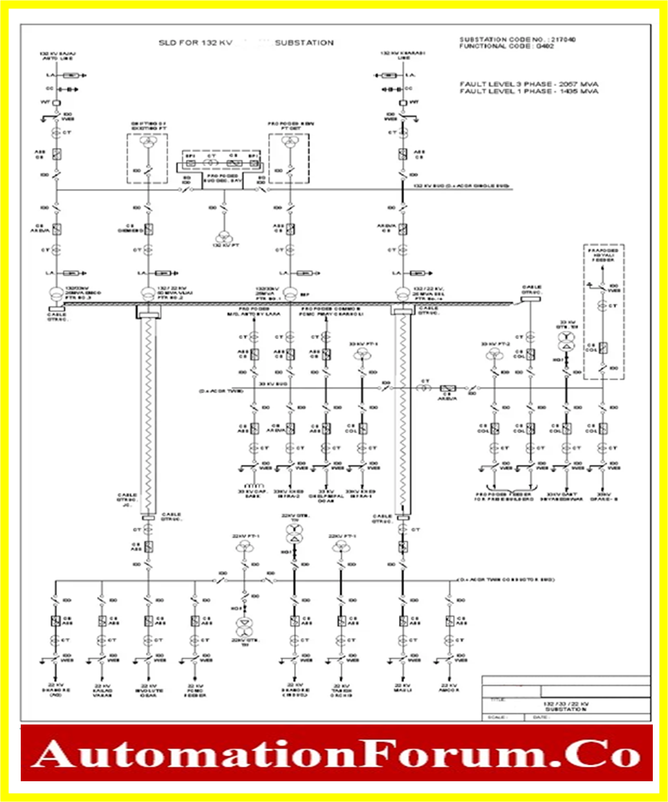
Example single line diagram (SLD) is shown below
How do you read a Single Line Drawing?
Reading a single-line drawing requires a basic understanding of electrical symbols and how they represent different components in an electrical system. Here are some general steps to follow when reading a single-line drawing:
- Start by identifying the power source and the loads being served. This will typically be shown at the top and bottom of the diagram.
- Follow the path of the electrical current through the diagram, from the power source to the loads. The electrical components and their interconnections will be represented by symbols such as switches, transformers, generators, motors, and other devices.
- Pay attention to the direction of the electrical current flow. In a single-line diagram, the electrical current typically flows from left to right, but this can vary depending on the specific diagram.
- Look for any protective devices, such as fuses or circuit breakers, that are installed in the system to protect against overloads and short circuits.
- Identify any control circuits or communication links that are used to operate and control the electrical system.
- Pay attention to any notes or labels that are included on the drawing. These can provide important information about the system, such as operating parameters, component ratings, and other details.
- Finally, use the single-line diagram to help troubleshoot the system if problems arise. By following the electrical current flow and identifying the various components, you can pinpoint the location of faults and take appropriate corrective action.
In summary, reading a single-line drawing requires knowledge of electrical symbols, an understanding of the path of the electrical current, and careful attention to the details included on the drawing.
How do you analyze a single-line diagram?
Listed here are 20 SLD symbols for the most important electrical and electronic engineering components.

Learn how to read a single-line diagram by looking at the example and explanation below.
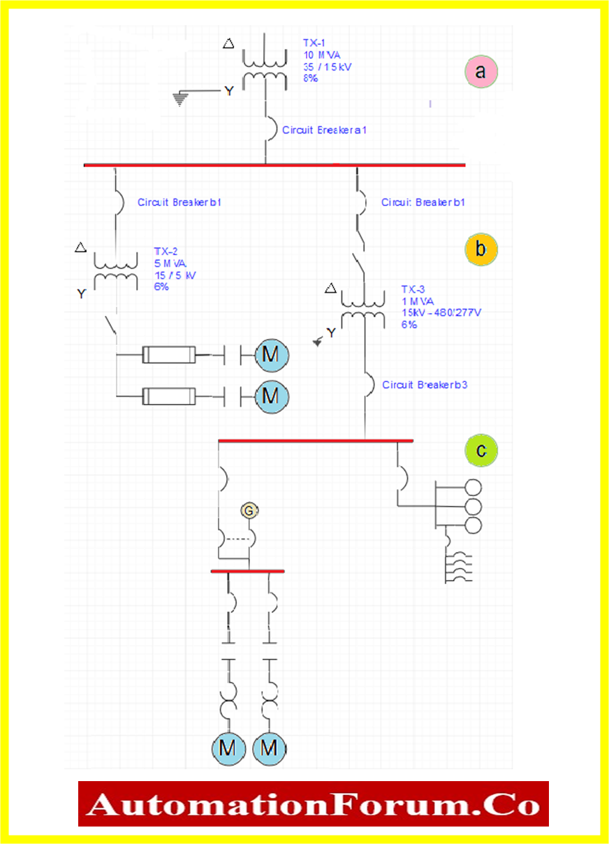
Section “a” in SLD represents
Starting at the top, you will see that a transformer is giving power to the whole system. The numbers next to the transformer symbol show that the transformer lowers the voltage from 35kV to 15kV.
After the voltage has been stepped down, a removable circuit breaker (a1) is found. Do you know what the symbol for a removable circuit breaker means? Since this circuit breaker is connected to the 15kV side of the transformer and the one-line doesn’t say anything different, you can assume it can handle 15kV.
After the transformer’s draw out circuit breaker (A1), it is connected to a heavier, horizontal line. This horizontal line is an electrical bus. An electrical bus is a way to get electricity to other places or circuits.
Section “b” in SLD represents
You’ll see that two more removable circuit breakers (b1 and b2) are connected to the bus and feed other 15kV circuits since there have been no signs that the system’s voltage has changed. A step-down transformer is connected to the removable circuit breaker (b1) to lower the voltage in that part of the system from 15kV to 5kV.
On the 5kV side of this transformer, a disconnect switch can be seen. The disconnect is used to connect or detach the equipment below it from the transformer. As there is no indication to the contrary, the equipment below the disconnect is 5kV. Do you know that the two pieces of equipment attached to the switch’s lower side are two medium-voltage motor starters? Depending on the needs of the system, more than one starter could be connected.
Find the second circuit breaker that can be taken out (b2). This circuit breaker is connected to a fused disconnect switch and a step-down transformer. Notice that all the equipment below the transformer is now considered low-voltage equipment because the voltage has been stepped down to 600 volts or less.
In the middle of the diagram, the last piece of electrical equipment is another circuit breaker (b3). The symbol shows that the circuit breaker this time is a fixed low-voltage circuit breaker. As you move to the bottom of the one-line, you’ll see that the middle circuit breaker (b3) is connected to the bottom bus.
Section “c” in SLD represents
Another fixed circuit breaker, which is at the bottom left and connected to the bus. Look carefully at the next group of symbols. Do you know the sign for an automatic transfer switch?
Also, notice that a circle symbol for an emergency generator is attached to the automatic transfer switch. This part of the one-line tells us that it’s important for the equipment connected below the automatic transfer switch to keep running even if the power from the bus goes out. If the power from the bus went out, the automatic transfer switch would hook up the emergency generator to the circuit to keep the equipment running.
A low-voltage bus connects the automatic transfer switch to a low-voltage motor control circuit. Be sure you know what these signs mean. Even though we don’t know what the low-voltage motor control in this circuit is for, it is clear that it is important to keep the equipment running. Usually, the details of the application would be written down in a specification.
Another fixed circuit breaker is connected to the bus on the right side of the third area. It is connected to a meter center, which is shown by the three-circle symbol. This means that the electric company uses these meters to keep track of how much power the equipment below the center of the meter uses.
Below the center of the meter, there is a load center or panel board that supplies power to several smaller circuits. This could be a building’s load center, which gives power to the lights, AC, heat, and any other electrical equipment in the building.
This oversimplified look at a one-line diagram will give you an idea of what these kinds of diagrams can tell you about the connections and equipment in an electrical system. Just remember that even though some one-line diagrams may look complicated because of their size and the number of different pieces of equipment they show, they can all be analyzed in the same step-by-step way.