
- What Software is Used for Instrumentation and Control Engineering?
- Instrumentation Engineering Software Comparison
- SmartPlant Instrumentation for Detailed Instrumentation Engineering
- AVEVA Instrumentation for Instrumentation Engineering
- Siemens COMOS for Instrumentation and Control Engineering
- Engineering Base for Instrumentation Detailed Engineering
- AutoCAD for Instrumentation Engineering
- AutoCAD Electrical for Instrumentation and Control Engineering
- EPLAN for Instrumentation and Control Engineering
- MicroStation for Instrumentation and EPC Engineering
- AVEVA Diagrams for P and ID and Instrumentation Engineering
- SmartPlant 3D for Instrumentation and Plant Design
- PDS for Plant and Instrumentation Engineering
- Microsoft Excel for Instrumentation Engineering
- SmartPlant Instrumentation vs AVEVA Instrumentation vs COMOS vs Engineering Base
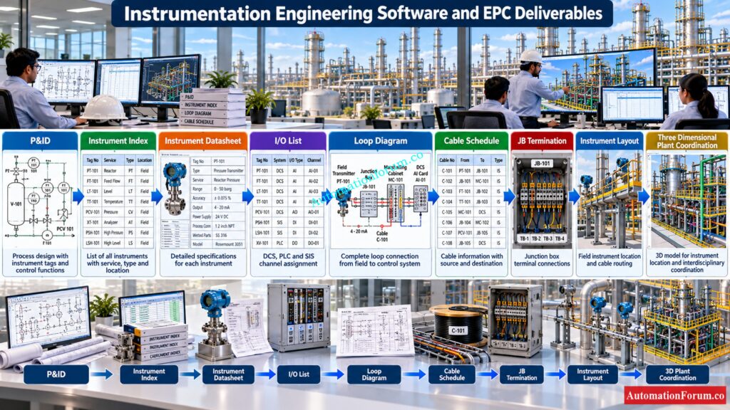
- Software Used for Instrumentation Engineering Deliverables
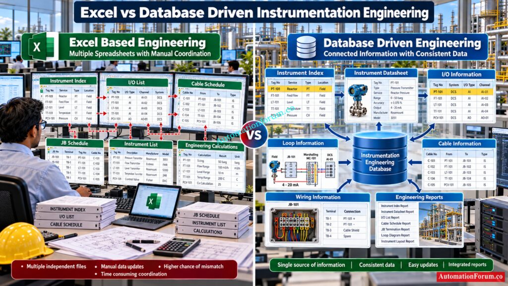
- Excel vs Database Driven Instrumentation Engineering Software
- How Instrumentation Engineering Software Supports an EPC Project
- Excel or Database Driven Software?
- Practical Instrumentation Software Workflow for Pressure Transmitter PT 101
- Common Instrumentation Engineering Software Problems
- Best Practices for Using Instrumentation Engineering Software
- Which Instrumentation Software Should an Engineer Learn?
- Frequently Asked Questions About Instrumentation Engineering Software
The software tools used in instrumentation and control detailed engineering are therefore more than drafting programs. Modern engineering platforms can manage instrument data, generate engineering documents, connect multidisciplinary information and support controlled engineering changes.
The main software categories include instrumentation database systems, integrated plant engineering platforms, CAD systems, electrical design software, three dimensional plant design systems and spreadsheet based engineering tools.
The actual software used depends on EPC standards, client requirements, project size, existing engineering systems, licenses and project execution methodology.
What Software is Used for Instrumentation and Control Engineering?
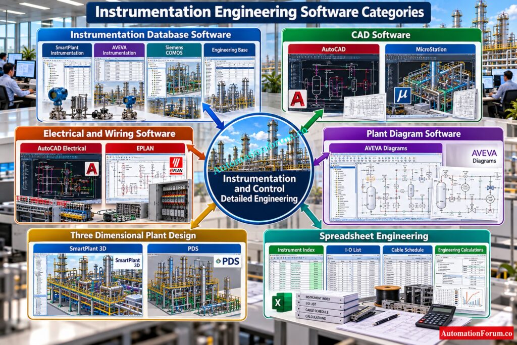
Common software used in EPC instrumentation engineering includes SmartPlant Instrumentation, AVEVA Instrumentation, Siemens COMOS, Engineering Base, AutoCAD, AutoCAD Electrical, EPLAN, MicroStation, AVEVA Diagrams, SmartPlant 3D, PDS and Microsoft Excel.
The important point is that these products serve different engineering purposes.
SmartPlant Instrumentation, AVEVA Instrumentation, COMOS and Engineering Base are particularly relevant when engineering data needs to be structured and connected.
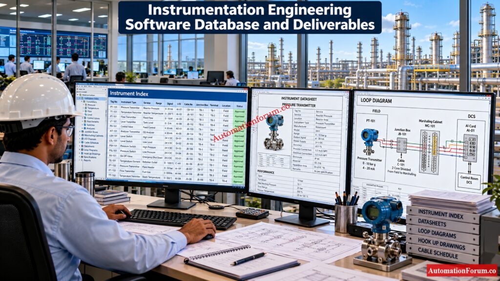
AutoCAD and MicroStation are primarily useful for engineering drawings. AutoCAD Electrical and EPLAN provide more specialized electrical and wiring documentation capabilities.
SmartPlant 3D and other plant design systems support spatial coordination between instrumentation and other plant disciplines.
Master Advanced Control Valve Sizing Tools Before Selecting Valves: Top 10 Control Valve Sizing Software Used in Process Industries
Instrumentation Engineering Software Comparison
| Software | Main category | Primary engineering purpose | Data management | Drawing capability | Typical EPC use |
| SmartPlant Instrumentation | Instrumentation database | Instrumentation detailed engineering | High | High | Large process and EPC projects |
| AVEVA Instrumentation | Instrumentation engineering | Instrument data and deliverables | High | High | Large integrated plant projects |
| Siemens COMOS | Integrated engineering platform | Multidiscipline plant engineering | High | High | Complex multidisciplinary projects |
| Engineering Base | Data centric engineering | Detailed plant engineering | High | High | Instrumentation, electrical and automation |
| AutoCAD | CAD | Engineering drafting | Low | High | Instrument drawings and layouts |
| AutoCAD Electrical | Electrical CAD | Wiring and electrical documentation | Medium | High | Panels, terminals and wiring |
| EPLAN | Electrical engineering | Electrical and control documentation | High | High | Control panels and wiring |
| MicroStation | CAD | Engineering drawings | Low | High | Plant layouts and multidisciplinary drawings |
| AVEVA Diagrams | Intelligent diagrams | Plant diagrams and engineering data | High | High | P and ID and diagram engineering |
| SmartPlant 3D | 3D plant design | Plant model coordination | High | High | Large EPC plant design |
| PDS | 3D plant design | Plant modelling | High | High | Plant design and coordination |
| Excel | Spreadsheet | Engineering data and schedules | Medium | Low | Indexes, lists, schedules and calculations |
SmartPlant Instrumentation for Detailed Instrumentation Engineering
What Is SmartPlant Instrumentation?
Its importance in an EPC environment comes from treating instrumentation information as engineering data rather than simply individual drawing files. Hexagon describes Smart Instrumentation as providing a single source of instrumentation information and using that information to create different engineering deliverables.
What Is SmartPlant Instrumentation Used For?
Typical project applications can include Instrument Index management, instrument specifications, datasheets, I O information, loop documentation, wiring information, cable information, hook ups and engineering reports.
An instrumentation engineer may create a pressure transmitter in the database and associate its service, signal, location and control system information with the instrument.
The same engineering information can then support downstream documentation depending on the project configuration.
SmartPlant Instrumentation in EPC Projects
SmartPlant Instrumentation can become a central instrumentation engineering environment between P and ID information and downstream documentation.
Actual functionality depends on the installed version, modules, configuration, project templates and EPC implementation.
Refer the below link for the 11 Best P&ID Software Tools for Process Design Engineers
AVEVA Instrumentation for Instrumentation Engineering
What Is AVEVA Instrumentation?
AVEVA Instrumentation is another major instrumentation engineering software category used for structured instrumentation design and documentation.
What Is AVEVA Instrumentation Used For?
One important advantage of a data centric approach is that engineers do not need to manually recreate the same instrument information in every document.
AVEVA Instrumentation for EPC Projects
For large projects, the ability to connect instrumentation information with wider plant engineering data can be important.
The engineer still needs to verify the generated documents because correct software output depends on correct engineering input, templates, rules and project configuration.
Unlock Critical HART Configuration Practices For Reliable DCS: Best Practices for Configuring HART Parameters in DCS Software
Siemens COMOS for Instrumentation and Control Engineering
What Is Siemens COMOS?
Siemens COMOS is an integrated plant engineering platform rather than a simple instrumentation drafting program.
Siemens describes COMOS as an object oriented platform with a consistent database connecting engineering, operations and modernization. Its portfolio includes process, automation, engineering and multidisciplinary plant design capabilities.
What Is COMOS Used for in Instrumentation?
COMOS can be used to connect instrumentation information with process, electrical and automation engineering.
This can include instrument objects, engineering data, I O information, control system engineering, documentation and lifecycle information depending on the configured modules.
COMOS also provides interfaces and data access mechanisms for engineering information and document management.
Explore Essential HMI Platforms For Modern Industrial Automation: Top HMI Software in Industrial Automation
Engineering Base for Instrumentation Detailed Engineering
What Is Engineering Base?
Engineering Base is a data centric engineering platform developed by AUCOTEC for plant engineering.
Engineering Base for Instrumentation Engineering
AUCOTEC specifically describes instrumentation workflows involving predefined specifications, typicals and generation of associated engineering objects and documentation.
Engineering Base can also connect process, electrical and automation information through a common data model. Its detailed engineering functions include plant infrastructure, cables, devices, loop typicals, PLC functions, control system data exchange and terminal documentation.
This makes it particularly relevant to projects where instrumentation cannot be separated from electrical and automation engineering.
Improve Calibration Control With Smarter Digital Management: Best Calibration Management Software
AutoCAD for Instrumentation Engineering
What Is AutoCAD Used for in Instrumentation?
AutoCAD remains important because many EPC projects require conventional engineering drawings.
Instrumentation engineers and designers can use AutoCAD for hook up drawings, instrument installation details, layouts, cable block diagrams, loop drawings and other project specific drawings.
AutoCAD is primarily a drafting environment. It does not automatically provide the same level of centralized instrumentation data management as a dedicated instrumentation engineering database.
This distinction is important.
An engineer can produce an excellent drawing in AutoCAD while still having inconsistent information between the drawing, Instrument Index and I O List.
Discover Free SCADA Platforms For Industrial Automation Projects: Best 12 Free SCADA Software for Industrial Automation
AutoCAD Electrical for Instrumentation and Control Engineering
AutoCAD Electrical is more specialized toward electrical control documentation.
It can support schematic documentation, wiring, terminals, panel documentation and engineering reports.
For instrumentation projects, it can be useful when control panels, marshalling panels, terminal connections and electrical interfaces must be documented.
Its value is strongest when instrumentation and electrical documentation overlap.
Choose Powerful PLC Programming Tools For Automation Engineering: Top 22 PLC programming software available in market?
EPLAN for Instrumentation and Control Engineering
EPLAN is an engineering software environment widely associated with electrical design and documentation.
For instrumentation and control projects, EPLAN can support wiring documentation, terminal connections, cable information, control panels and electrical interfaces.
It becomes particularly useful when the project contains significant control panel and electrical documentation in addition to conventional instrumentation drawings.
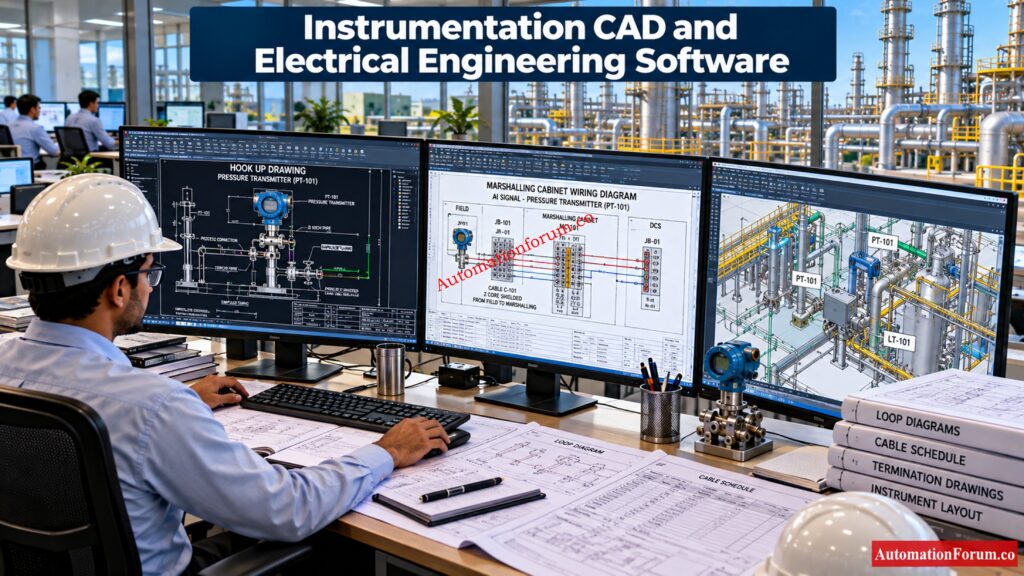
The engineer should understand that EPLAN and instrumentation database systems may perform complementary roles rather than being direct substitutes.
Test Your Knowledge Of Advanced DCS Documentation Practices: Advanced DCS Documentation Quiz for Process Industries with Answers and Explanations
MicroStation for Instrumentation and EPC Engineering
MicroStation is a CAD platform used for engineering drawing and design work.
Within EPC projects, it can be used for layouts, plant drawings and other engineering documentation depending on company standards.
Instrumentation designers may encounter MicroStation when working with multidisciplinary plant drawings prepared by piping, structural or civil engineering teams.
The important skill is therefore not simply knowing how to draw. Engineers need to understand how instrumentation information relates to the overall plant layout.
Strengthen PLC Alarm And Trip Documentation Before Commissioning: PLC Alarm and Trip Documentation Procedure – EPC PLC Automation Engineer Guide
AVEVA Diagrams for P and ID and Instrumentation Engineering
AVEVA Diagrams supports intelligent diagram based engineering within the wider AVEVA environment.
For EPC projects, diagram based engineering can connect process and plant information with engineering data.
This is particularly relevant for P and ID based workflows where instrumentation information originates from process diagrams and then moves into detailed engineering.
The advantage of intelligent diagramming is that the drawing can become part of the engineering data environment rather than remaining an isolated graphical document.
Refer the below link for the 82 Essential Drawings and Documents for Instrumentation and Control Engineers
SmartPlant 3D for Instrumentation and Plant Design
SmartPlant 3D is a three dimensional plant design environment.
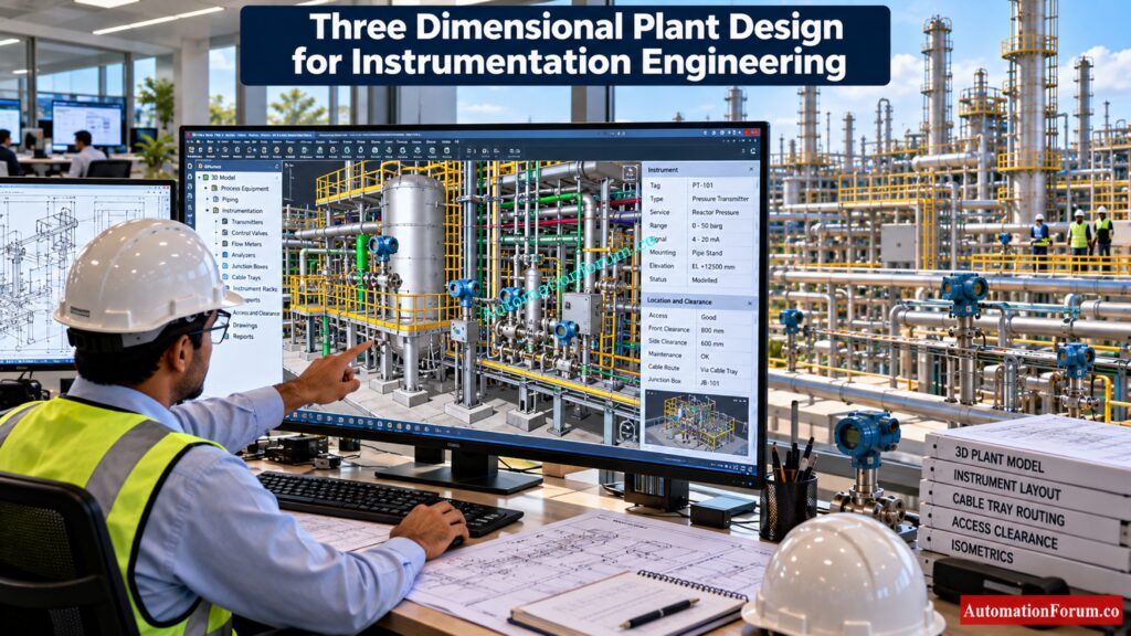
Instrumentation engineers may interact with three dimensional plant models when reviewing instrument locations, control valves, junction boxes, analyzer installations, instrument racks and access requirements.
The instrumentation engineer normally does not use three dimensional modelling in isolation. The work must be coordinated with piping, equipment, electrical and structural disciplines.
Three dimensional review can identify practical problems such as inaccessible transmitters, insufficient maintenance space or unsuitable cable routing locations before construction.
Understand Shutdown Documentation Before Designing Emergency Systems: Shutdown Philosophy: Engineering Documentation for Process Safety and Emergency Shutdown Systems
PDS for Plant and Instrumentation Engineering
PDS is another plant design system encountered in EPC environments.
It supports three dimensional plant design and multidisciplinary engineering coordination.
Instrumentation engineers may use information from the plant model to verify instrument locations, installation arrangements and physical coordination with equipment and piping.
Its relevance therefore extends beyond drawing production into physical plant coordination.
Build Complete PLC Documentation For Reliable Plant Operations: PLC System Documentation Guide: Essential Records for Industrial Automation
Microsoft Excel for Instrumentation Engineering
Excel remains one of the most widely used engineering tools because it is flexible and easy to exchange.
Instrumentation engineers commonly use Excel for Instrument Indexes, I O Lists, cable schedules, junction box schedules, instrument lists, engineering registers and calculations.
Excel is particularly practical for small and medium engineering activities.
The limitation appears when many engineers maintain independent copies of the same information.
For example, an instrument tag can have one cable number in an Excel cable schedule and another number in a manually prepared loop drawing. A database driven system can reduce this type of disconnected information when properly implemented.
Test Your Expertise In Instrumentation I O Documentation: Quiz on Instrumentation I/O List Engineering Documentation
SmartPlant Instrumentation vs AVEVA Instrumentation vs COMOS vs Engineering Base
| Engineering factor | SmartPlant Instrumentation | AVEVA Instrumentation | Siemens COMOS | Engineering Base |
| Main focus | Instrumentation engineering | Instrumentation and electrical engineering | Integrated plant engineering | Multidiscipline data centric engineering |
| Instrument database | Yes | Yes | Yes | Yes |
| Instrument Index | Yes | Yes | Yes | Yes |
| Instrument datasheets | Yes | Yes | Yes | Yes |
| I O engineering | Yes | Yes | Yes | Yes |
| Loop engineering | Yes | Yes | Yes | Yes |
| Cable information | Yes | Yes | Yes | Yes |
| Wiring information | Yes | Yes | Yes | Yes |
| Multidiscipline integration | Project dependent | Strong integration options | Strong | Strong |
| Three dimensional integration | Project dependent | Available through wider AVEVA environment | Available | Available depending on implementation |
| Typical application | Instrumentation detailed engineering | Integrated instrumentation and electrical engineering | Complete plant lifecycle engineering | Integrated detailed plant engineering |
| Main engineering concept | Instrument database | Data centric engineering | Object based plant engineering | Shared engineering data model |
The capabilities shown are general software capabilities. Actual functionality depends on product version, modules, licenses, project configuration, templates and EPC implementation.
Download Practical Engineering Templates For Faster Project Execution: Downloadable Engineering Documentation Instrumentation and Control Templates
Software Used for Instrumentation Engineering Deliverables
| Engineering deliverable | Common software approach |
| Instrument Index | Excel, SmartPlant Instrumentation, AVEVA Instrumentation, COMOS, Engineering Base |
| I O List | Excel, COMOS, Engineering Base, instrumentation databases |
| Instrument Datasheet | SmartPlant Instrumentation, AVEVA Instrumentation, COMOS, Engineering Base |
| Loop Diagram | Instrumentation databases, AutoCAD |
| Hook Up Drawing | AutoCAD, MicroStation, instrumentation systems |
| Cable Schedule | Excel, instrumentation databases, Engineering Base |
| JB Termination | Excel, AutoCAD Electrical, instrumentation systems |
| Wiring Drawing | AutoCAD Electrical, EPLAN, instrumentation systems |
| Instrument Layout | AutoCAD, MicroStation, plant design systems |
| Three Dimensional Coordination | SmartPlant 3D and other plant design systems |
Excel vs Database Driven Instrumentation Engineering Software
| Software | Primary use | Instrumentation application | Electrical application | 2D drawings | 3D capability | Typical user |
| AutoCAD | General CAD drafting | Hook ups, layouts, diagrams | Basic | Yes | Limited depending on workflow | Instrument designer |
| AutoCAD Electrical | Electrical CAD | Control interfaces | Wiring, terminals and panels | Yes | Limited | Electrical and control engineer |
| EPLAN | Electrical engineering | Instrument wiring interfaces | Wiring, terminals and panels | Yes | Project dependent | Electrical and automation engineer |
| MicroStation | Engineering CAD | Plant layouts and drawings | Multidiscipline drawings | Yes | Yes through associated products | EPC designer |
How Instrumentation Engineering Software Supports an EPC Project
A typical workflow starts with P and ID review and instrument identification.
- The engineering team develops the Instrument Index and instrument specifications. Datasheets are prepared and I O information is developed.
- The control system engineer then works with PLC, DCS or SIS allocation. Instrument designers develop hook ups, loop diagrams and installation information.
- Cable schedules, junction box schedules and termination information are developed as the physical signal architecture becomes clearer.
- Three dimensional plant design is used for location and access coordination.
- During procurement, instrumentation software supports technical information and vendor document review. During construction, drawings and schedules support installation.
- During commissioning, loop diagrams, termination drawings, I O information and instrument datasheets become important field documents.
- Finally, engineering changes identified during construction and commissioning must be incorporated into the final as built documentation.
Build Accurate Instrument Indexes From Engineering Data: Instrument Index: Definition, Example, Template and How to Create One
Excel or Database Driven Software?
Excel is flexible and inexpensive compared with specialized engineering systems. It is suitable when the engineering data volume and project complexity are manageable.
Database driven software becomes more valuable when the project contains thousands of instruments and complex relationships between instruments, loops, cables, I O points, terminals and drawings.
The key question is not whether Excel is good or bad.
The real question is whether the project can maintain one controlled and reliable source of engineering information.
Practical Instrumentation Software Workflow for Pressure Transmitter PT 101
Consider pressure transmitter PT 101.
The P and ID identifies PT 101. The Instrument Index stores its tag and service. The instrumentation database can hold its specification and signal information.
The I O List assigns the DCS channel. The cable schedule identifies the field cable. The junction box schedule defines the terminal. The loop diagram represents the complete signal path.
The hook up defines physical installation while the plant model or layout verifies location and access.
If PT 101 changes from one DCS channel to another, the engineering team must identify every affected document.
This is where connected engineering software provides a significant workflow advantage. The purpose is not simply to generate drawings faster. The purpose is to maintain engineering consistency.
Understand Vendor Documentation Requirements Before Systems Integration: Vendor Document for Project Systems Architecture: Complete Engineering Guide for Instrumentation, Automation and Control
Common Instrumentation Engineering Software Problems
- Another problem occurs when engineers assume that automatically generated documents are automatically correct.
- Software follows its database, rules, templates and configuration. If the engineering data is wrong, the generated documents can also be wrong.
- Engineering review therefore remains essential.
Control Alarm And Trip Settings With Better Engineering Records: Alarm & Trip Setpoint List in Instrumentation Engineering
Best Practices for Using Instrumentation Engineering Software
- Start with approved project templates.
- Maintain controlled tag numbering.
- Use consistent engineering data across Instrument Index, I O List, datasheets and drawings.
- Control revisions carefully.
- Validate I O allocation before issuing control system documentation.
- Check cable and termination information before construction release.
- Review vendor documents before importing information into the engineering database.
- Perform multidisciplinary reviews with process, piping, electrical, mechanical and control system teams.
- Update engineering information after commissioning changes.
- Maintain accurate as built information.
Master Engineering Drawing Requirements For Instrumentation Projects: Types of Engineering Drawings and Documents used in Instrumentation
Which Instrumentation Software Should an Engineer Learn?
- A fresh engineer should first learn instrumentation fundamentals, P and IDs, signal types, I O concepts, loop diagrams and engineering standards.
- Excel and AutoCAD provide useful foundations for understanding engineering documentation.
- An EPC instrumentation designer should develop strong drafting and documentation skills.
- An instrumentation engineer should learn the database driven platform used by the organization, such as SmartPlant Instrumentation, AVEVA Instrumentation, COMOS or Engineering Base.
- A control system engineer should understand I O databases, PLC, DCS and SIS engineering.
- A commissioning engineer should be comfortable reading loop diagrams, termination drawings, I O Lists and cable schedules.
- Senior engineers should understand not only software operation but also data relationships, engineering change control, multidisciplinary interfaces and project standards.
The most valuable skill is not knowing the largest number of software packages. It is understanding instrumentation engineering well enough to know whether the software output is technically correct.
Calculate Junction Box Loading Before Finalizing Field Design: Junction Box Load Calculator
Frequently Asked Questions About Instrumentation Engineering Software
What software is best for instrumentation engineers?
There is no single best software because the choice depends on the EPC project and engineering workflow. SmartPlant Instrumentation, AVEVA Instrumentation, COMOS and Engineering Base are widely used for structured instrumentation engineering.
Which software is used for MEP?
What software tools are commonly used by instrumentation engineers?
Common tools include SmartPlant Instrumentation, AVEVA Instrumentation, COMOS, Engineering Base, AutoCAD, EPLAN and Excel. Control system engineering may also require PLC, DCS, SIS and configuration software.
What are the basic tools used in instrumentation?
Basic instrumentation tools include a multimeter, loop calibrator, pressure calibrator, temperature source and HART communicator. Engineers also use engineering drawings, datasheets, calibration documents and software tools for design and commissioning.
What are some software engineering tools?
Software engineering commonly uses tools for coding, version control, testing, debugging, documentation and project management. Examples include Git, Visual Studio Code, Jira, GitHub and various programming and testing platforms.
What software is commonly used for instrumentation engineering?
SmartPlant Instrumentation, AVEVA Instrumentation, COMOS, Engineering Base, AutoCAD, EPLAN, AutoCAD Electrical and Excel are commonly encountered in EPC projects. The selected tools depend on project standards, client requirements and engineering scope.
What is SmartPlant Instrumentation used for?
What is AVEVA Instrumentation used for?
AVEVA Instrumentation supports structured instrumentation engineering and management of instrument data. It can also connect instrumentation information with broader data centric plant engineering workflows.
What is COMOS used for in instrumentation?
COMOS provides an integrated engineering environment connecting instrumentation and automation information with wider plant engineering data. It supports consistent engineering information across multiple disciplines and project stages.
What is Engineering Base used for?
Engineering Base supports process, instrumentation, electrical and automation engineering using a common engineering data model. It helps engineers create and manage detailed engineering information within an integrated environment.
Is AutoCAD important for instrumentation engineers?
Yes, AutoCAD remains useful for creating and modifying many instrumentation engineering drawings. It is commonly used for hook ups, layouts, installation drawings and project specific documentation.
Which software is used for instrument datasheets?
Database driven platforms such as SmartPlant Instrumentation, AVEVA Instrumentation, COMOS and Engineering Base can support structured instrument datasheet engineering. Excel may also be used when project requirements are simpler.
Which software is used for I O Lists?
Excel is widely used for preparing and managing I O lists on many projects. Integrated platforms such as COMOS, Engineering Base and dedicated instrumentation systems can maintain I O information within a larger engineering database.
Is Excel enough for an EPC instrumentation project?
Excel can be sufficient for smaller projects and individual engineering activities. Large EPC projects usually benefit from centralized engineering databases that provide better data consistency, revision control and relationships between deliverables.
What software should a new instrumentation engineer learn?
A new instrumentation engineer should begin with Excel and CAD fundamentals before learning specialized instrumentation software. The next step should be the instrumentation database, plant design or control system software used by the target EPC organization.
Refer the below link for the Instrument Index Generator for EPC Instrumentation Projects
