
- Why Correct Radar Beam Angle Is Important for Instrumentation Engineers
- What Is the Beam Angle of a Radar Level Transmitter?
- Why Is Beam Angle Important in Radar Level Measurement?
- Relationship Between Radar Frequency and Beam Angle
- How Antenna Size Affects Radar Level Transmitter Beam Angle
- Wide Beam Angle Versus Narrow Beam Angle in Radar Level Transmitters
- Effect of Radar Beam Angle on Tank Wall Reflections
- Radar Beam Angle and Tank Internal Obstructions
- Radar Beam Angle and Nozzle Installation
- 26 GHz Versus 80 GHz Radar Level Transmitter Beam Angle
- Does a Narrower Radar Beam Angle Always Mean Better Accuracy?
- How to Select the Correct Beam Angle for a Radar Level Transmitter
- Common Radar Level Transmitter Beam Angle Selection Mistakes
- Radar Level Transmitter Beam Angle Practical Example
- Radar Beam Angle During Level Transmitter Commissioning
- Radar Beam Angle Troubleshooting Guide
- Frequently Asked Questions About Radar Level Transmitter Beam Angle
- Final Engineering Takeaway on Beam Angle of Radar Level Transmitter
Why Correct Radar Beam Angle Is Important for Instrumentation Engineers
Imagine a radar level transmitter installed on a process vessel where the liquid level is actually stable, but the DCS indication keeps moving. The transmitter itself may be healthy. The problem could be that the radar signal is reflecting from an agitator, tank wall, heating coil, internal pipe, ladder, or another obstruction before the transmitter receives the actual product surface echo.
This is where the importance of beam angle of a radar level transmitter becomes clear. Beam angle determines how widely the radar energy spreads inside the vessel and therefore influences what the radar can encounter before reaching the product surface.
For instrumentation engineers, beam angle should be considered during transmitter selection, nozzle design, installation, commissioning, and troubleshooting. It should never be evaluated separately from frequency, antenna design, tank geometry, internal equipment, and process conditions.
What Is the Beam Angle of a Radar Level Transmitter?
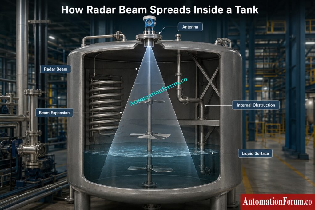
How Does a Radar Level Transmitter Beam Spread Inside a Tank?
The beam angle of a radar level transmitter describes the angular spread of the electromagnetic energy emitted from its antenna. The radar signal does not travel downward as an infinitely narrow line. Instead, it spreads through the vessel as it moves toward the product surface.
What Determines the Beam Angle of a Radar Level Transmitter?
As the distance from the antenna increases, the area covered by the radar beam also becomes larger. This means an obstruction that is outside the beam close to the transmitter can potentially fall inside the beam farther down in the vessel.
Why Does Radar Beam Width Increase With Measuring Distance?
The actual beam pattern depends on several factors, including radar frequency, antenna aperture, antenna type, and transmitter construction. Therefore, engineers should always use the manufacturer’s published beam angle rather than trying to calculate the exact value from frequency alone.
Refer the below link for the Radar Level Transmitter False Echo Troubleshooting Guide
Why Is Beam Angle Important in Radar Level Measurement?
How Beam Angle Affects Radar Level Measurement Accuracy
Beam angle is important because the radar signal needs a reasonably clear path between the antenna and the product surface.
Consider a vessel containing an agitator, heating coil, and internal support structure. If the radar beam intersects these objects, each one can produce a reflection. The transmitter may then receive several echoes instead of one clear surface echo.
How Beam Angle Helps Prevent False Radar Echoes
The unwanted reflection can appear as a false echo or interfere with the actual product surface signal. The result may be an unstable level indication, incorrect level, multiple echoes, or occasional loss of measurement.
The same principle applies to tank walls, ladders, dip pipes, baffles, internal nozzles, support beams, and other metallic structures.
Why Proper Radar Installation Matters More Than Signal Processing
Modern radar transmitters have advanced signal processing and false echo handling capabilities. However, signal processing should not be considered a replacement for proper mechanical installation. A good installation gives the transmitter a much better starting point.
Fix unstable radar readings with proven troubleshooting methods: Step by Step Guide to Troubleshooting Radar Level Transmitters
Relationship Between Radar Frequency and Beam Angle
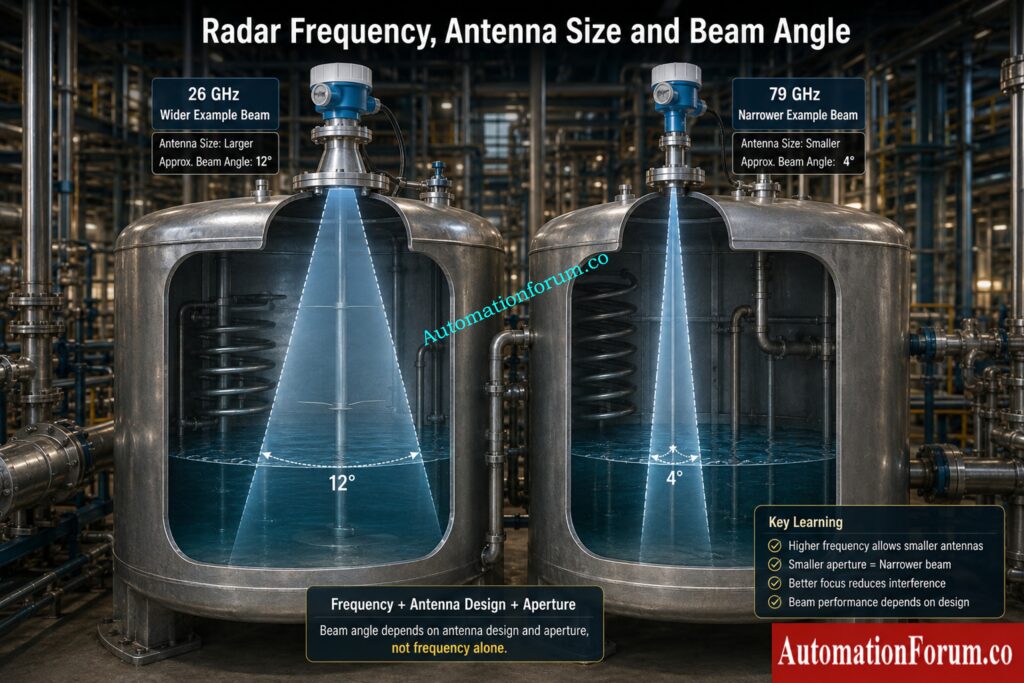
How Radar Frequency Affects Beam Angle
For example, a radar transmitter operating around 26 GHz with an antenna aperture of approximately 80 mm can have a beam angle of approximately 12 degrees. A transmitter operating around 79 GHz with a similar antenna aperture can have a beam angle of approximately 4 degrees.
These values should be treated only as engineering examples. They are not universal specifications for every 26 GHz or 79 GHz radar transmitter.
Why Radar Frequency Alone Cannot Determine Beam Angle
The actual beam angle depends on antenna design, aperture, frequency, and transmitter construction. This is why the manufacturer’s technical data should always be checked during instrument selection.
The important engineering principle is that frequency, wavelength, and antenna aperture work together to determine how strongly the radar signal can be focused.
Calculate tank level accurately before selecting radar settings: Radar Level Transmitter Calculator for Tank Level Measurement
How Antenna Size Affects Radar Level Transmitter Beam Angle
How Antenna Aperture Controls Radar Beam Focusing
Antenna aperture has a major influence on radar beam focusing. For a given frequency, increasing the effective antenna aperture generally allows the radar energy to be concentrated into a narrower beam.
This becomes useful when the transmitter must measure inside a narrow vessel or when internal equipment is present. A more focused beam can make it easier to position the radar so that the main signal avoids unwanted structures.
Horn Antenna Versus Lens Antenna Beam Angle
Horn antennas and lens antennas can have different beam characteristics even when used at similar frequencies. The physical antenna design therefore matters just as much as the nominal radar frequency.
How to Select the Correct Radar Antenna for Beam Angle
Engineers should not select an antenna based only on the smallest available beam angle. The antenna must also suit the process, nozzle dimensions, measuring range, product characteristics, and installation arrangement.
Catch critical radar installation mistakes before commissioning begins: Radar Level Measurement Performance Checklist
Wide Beam Angle Versus Narrow Beam Angle in Radar Level Transmitters
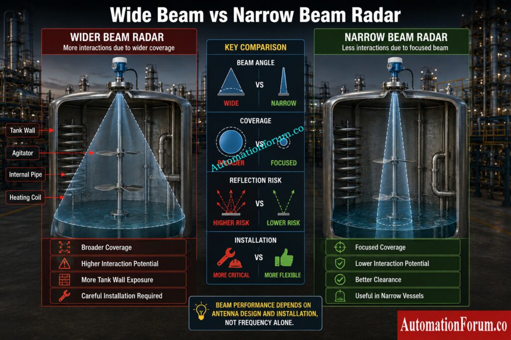
| Parameter | Wider Beam Angle | Narrower Beam Angle |
| Radar coverage | Larger coverage area | More focused coverage area |
| Tank wall interaction | Higher possibility in narrow vessels | Lower possibility when correctly positioned |
| Internal structures | Greater possibility of interaction | Easier to avoid when correctly positioned |
| Narrow vessels | Requires careful installation | Often advantageous |
| Measurement area | Broader area | More concentrated area |
| Installation | Requires attention to surrounding geometry | Can provide greater flexibility in some applications |
Wide Beam Angle Versus Narrow Beam Angle Comparison
A wider beam is not automatically a problem. There are applications where broader coverage of the product surface can be useful. If the vessel is relatively open and there are no significant obstructions, a wider beam may work perfectly well.
Does a Narrower Radar Beam Always Give Better Measurement?
A narrow beam can be advantageous when the vessel contains internal equipment or when the transmitter has limited space between the mounting location and tank wall.
However, one point should always be remembered.
A narrower beam angle does not automatically mean higher measurement accuracy.
Beam angle mainly describes the spread of radar energy. Actual measurement performance depends on the complete application.
Solve difficult guided wave radar measurement problems faster: Guided Wave Radar Level Transmitters Troubleshooting Guide
Effect of Radar Beam Angle on Tank Wall Reflections
How Tank Walls Create Unwanted Radar Echoes
Tank wall reflection is an important consideration when installing radar level transmitters.
If the transmitter is mounted close to the vessel wall and the radar beam is relatively wide, part of the signal may strike the wall. The reflected signal can return toward the antenna and appear as an unwanted echo.
How Tank Welds and Internal Features Affect Radar Echoes
The situation can become more complicated because tanks may contain welds, structural features, internal coatings, buildup, or other reflective surfaces.
This does not mean that the radar beam must always be completely isolated from every part of the tank. The acceptable installation depends on the transmitter design and manufacturer’s installation recommendations.
The practical objective is to position the radar so that the main measurement beam has the clearest practical path toward the product surface.
Verify guided wave radar installation details before startup: Guided Wave Radar Level Transmitter Installation Checklist
Radar Beam Angle and Tank Internal Obstructions
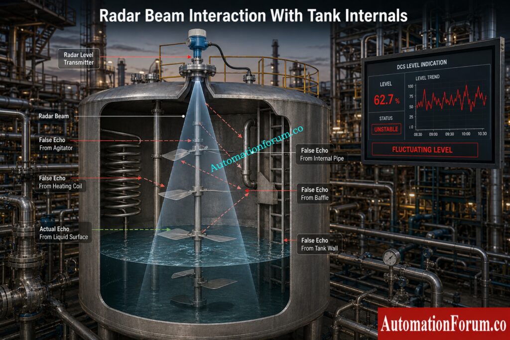
- Before selecting a radar level transmitter, the engineer should review the vessel drawing and identify the internal equipment.
- Important items include agitators, heating coils, ladders, dip pipes, baffles, support beams, internal pipes, internal nozzles, and other metallic structures.
- An agitator requires special attention because its position and movement can create changing reflection conditions. A radar signal may appear stable when the agitator is stopped and become unstable when the agitator operates.
- Heating coils can also create strong reflections because they may extend across a significant part of the vessel.
- The engineer should therefore examine the complete radar beam path at the expected measuring distance rather than looking only at the area immediately below the antenna.
Avoid costly level transmitter selection mistakes during EPC: Level Transmitter Selection Checklist for EPC Engineers
Radar Beam Angle and Nozzle Installation
- Nozzle geometry can significantly influence radar installation.
- The engineer should check nozzle diameter, nozzle length, nozzle height, antenna position, antenna extension, and the internal geometry around the nozzle.
- A long or narrow nozzle can introduce unwanted reflections or restrict the radar signal before it enters the main vessel.
- The transmitter should also be correctly aligned. Poor alignment can direct the radar beam toward a tank wall or internal structure.
- This is why transmitter selection should be based on the actual mechanical installation rather than simply choosing a transmitter with the highest operating frequency.
Discover how tank geometry silently affects measurement accuracy: Effect of Tank Design on Accuracy of Level Measurement
26 GHz Versus 80 GHz Radar Level Transmitter Beam Angle
- From a beam angle perspective, higher frequency radar can provide a narrower beam when the antenna aperture and design are comparable.
- A 26 GHz radar has a longer wavelength than an approximately 80 GHz radar. With suitable antenna construction, the higher frequency can provide stronger beam focusing.
- This can be useful in narrow vessels or applications where the radar must avoid internal structures.
- However, 80 GHz radar is not automatically the best choice for every application. A proper selection must consider vessel geometry, measuring range, antenna design, nozzle arrangement, product characteristics, surface behaviour, internal equipment, and required measurement performance.
- The earlier example of approximately 12 degrees at 26 GHz and approximately 4 degrees at 79 GHz illustrates the engineering principle rather than establishing a universal specification.
Refer the below link for the Calibration Procedures for Level Measurement Devices
Does a Narrower Radar Beam Angle Always Mean Better Accuracy?
No.
Beam angle describes the angular spread of the radar energy. It does not independently determine measurement accuracy.
Radar level measurement performance can also be affected by transmitter design, antenna design, signal processing, product dielectric characteristics, surface condition, tank geometry, mounting position, echo quality, calibration, foam, vapour, agitation, condensation, and buildup.
Why Narrow Beam Angle Does Not Guarantee Better Accuracy
A narrower beam can reduce unwanted reflections in some applications, which may improve measurement stability. However, a narrow beam directed toward an unsuitable part of the vessel will not automatically produce a better measurement.
The correct approach is to evaluate beam angle as one part of the complete radar measurement system.
Master industrial level measurement before choosing the right technology: Mastering Level Measurement Technologies
How to Select the Correct Beam Angle for a Radar Level Transmitter
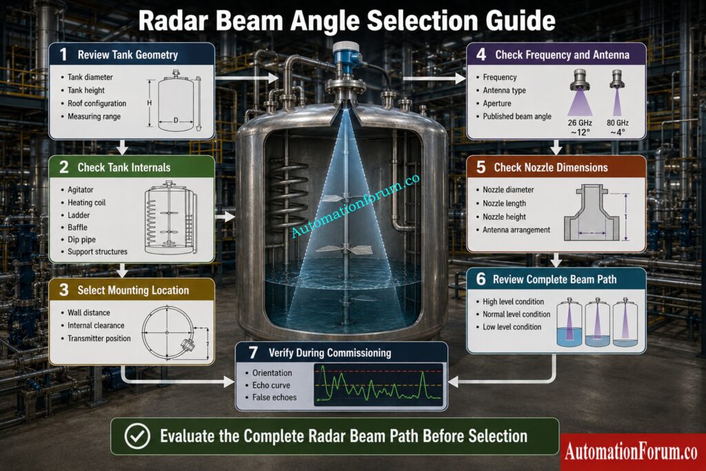
Step 1: Review Tank Geometry
Determine the tank diameter, tank height, roof configuration, measuring range, and expected product levels. The beam footprint becomes larger as the radar travels farther, so the available clearance must be considered throughout the measurement range.
Step 2: Check Tank Internal Structures
Identify agitators, heating coils, ladders, dip pipes, baffles, support structures, and internal pipes. Determine whether any of these objects could fall inside the radar beam.
Discover practical submersible level measurement solutions for industry: Submersible Level Transmitters Applications and Working Principles
Step 3: Select the Radar Mounting Location
Evaluate the distance from the antenna to the tank wall and nearby internal equipment. Sometimes changing the mounting location is a better solution than replacing the transmitter.
Step 4: Check Radar Frequency and Antenna Type
Review operating frequency, antenna aperture, antenna type, and manufacturer’s published beam angle. These parameters should be evaluated together.
Step 5: Check Radar Nozzle Dimensions
Verify nozzle diameter, nozzle length, nozzle height, and antenna arrangement. Make sure the transmitter is suitable for the actual nozzle rather than relying on general assumptions.
Step 6: Review the Complete Radar Beam Path
The most important question is simple: what will the radar signal encounter between the antenna and the product surface?
Review the beam path at high level, normal operating level, and low level. An obstruction that is harmless at one level may become important at another.
Fix closed tank DP level measurement problems faster: Closed Tank DP Level Transmitter Troubleshooting Guide
Step 7: Verify the Radar Installation During Commissioning
Check the transmitter orientation, antenna installation, mounting location, echo curve, false echoes, actual level, signal stability, and measuring range.
See when capacitance and radar work better together: Hybrid Level Measurement Capacitance and Guided Wave Radar
Common Radar Level Transmitter Beam Angle Selection Mistakes
- Selecting radar based only on frequency is a common mistake. Frequency matters, but it does not tell the engineer everything about beam behaviour.
- Ignoring antenna aperture can also result in incorrect expectations about beam focusing.
- Another common mistake is failing to review tank internals. An instrument specification may look excellent on paper, but the radar beam can still intersect an agitator or heating coil.
- Mounting too close to the tank wall is another problem that deserves attention, especially in narrow vessels.
- Ignoring nozzle geometry can also create installation difficulties.
- Some engineers assume that a narrow beam will solve every radar measurement problem. It will not. Surface turbulence, foam, vapour, condensation, poor installation, and unsuitable process conditions can still affect measurement.
- Finally, relying completely on signal processing to compensate for poor installation can create unnecessary troubleshooting work later.
Calculate open tank level values quickly and accurately: Open Tank Level Transmitter Calculator
Radar Level Transmitter Beam Angle Practical Example
Consider a vertical process vessel containing an agitator and an internal heating coil. A radar transmitter is installed on the vessel roof.
During normal operation, the actual liquid level remains relatively steady. But once in a while the DCS indication goes up and down without any matching process change.
The instrumentation engineer reviews the echo curve first. Several echoes are visible. The actual surface echo is present, but additional reflections are also appearing.
The engineer then reviews the transmitter mounting location and vessel drawing. The radar beam is found to pass close to the agitator and heating coil.
The next step is not necessarily to replace the transmitter.
The engineer checks whether the transmitter can be repositioned. The nozzle dimensions are checked and the beam angle is compared with the actual internal arrangement.
If repositioning is not practical, a transmitter with a more focused beam may be considered if it is suitable for the application.
This approach is more reliable than changing instruments without first identifying the physical source of the unwanted echo.
Access powerful level measurement calculators for engineers: Level Measurement Calculators for Industrial Instrumentation
Radar Beam Angle During Level Transmitter Commissioning
During commissioning, the engineer should verify that the installed arrangement matches the design assumption.
Check the transmitter orientation, nozzle arrangement, antenna installation, mounting position, tank internals, echo curve, false echoes, actual level, signal stability, and measurement range.
Where practical, observe the radar signal at different product levels. This is particularly useful in vessels where internal structures are located at different distances from the antenna.
If an agitator is present, compare radar behaviour when the agitator is stopped and when it is operating.
A commissioning engineer should not immediately adjust damping or false echo settings simply because the level signal is unstable. The physical beam path should be investigated first.
Radar Beam Angle Troubleshooting Guide
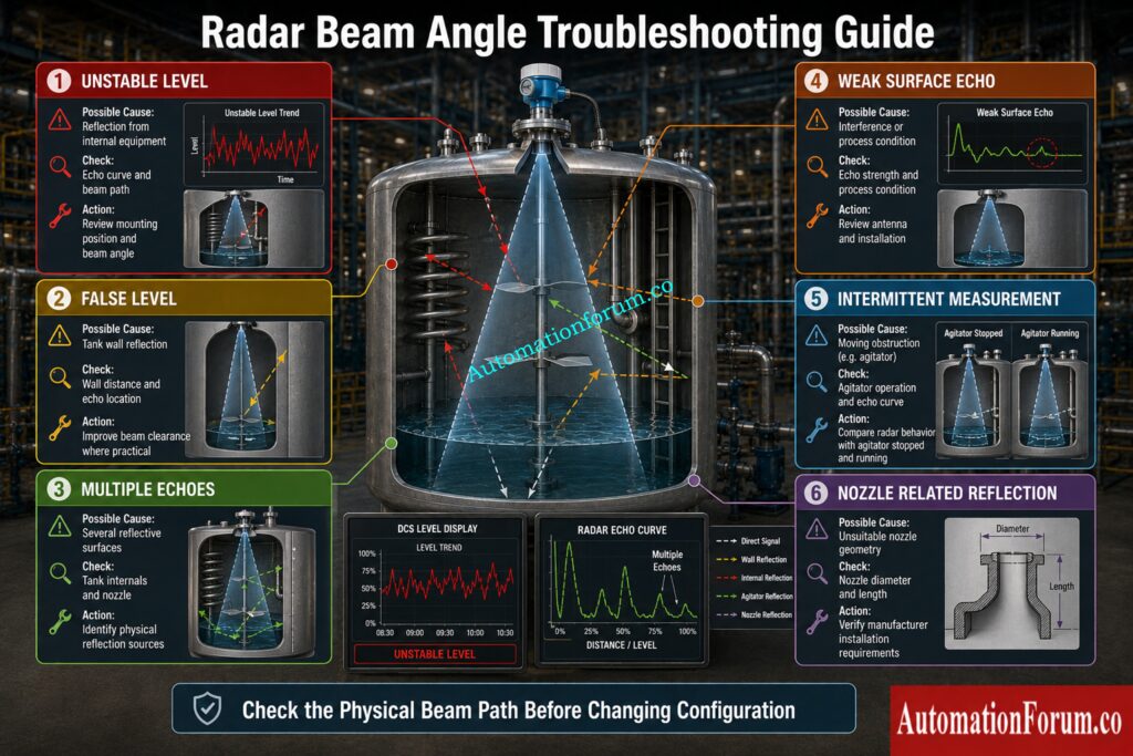
| Observed Problem | Possible Beam Related Cause | What to Check | Recommended Engineering Action |
| Unstable level | Reflection from internal equipment | Echo curve and beam path | Review mounting position and beam angle |
| False level | Tank wall reflection | Wall distance and echo location | Improve beam clearance where practical |
| Multiple echoes | Several reflective surfaces | Tank internals and nozzle | Identify physical sources before configuration changes |
| Weak surface echo | Interference or process condition | Echo strength and process condition | Review antenna and installation |
| Intermittent measurement | Moving obstruction | Agitator operation and echo curve | Compare operation with agitator stopped and running |
| Low level error | Bottom or internal reflection | Beam footprint at low level | Review tank geometry and transmitter position |
| Echo loss | Poor signal path or process condition | Echo curve and surface condition | Investigate installation and process conditions |
| Nozzle related reflection | Unsuitable nozzle geometry | Nozzle diameter and length | Check manufacturer installation requirements |
Test your closed tank measurement troubleshooting knowledge: Closed Tank Level Measurement Troubleshooting Quiz
Frequently Asked Questions About Radar Level Transmitter Beam Angle
What is beam angle in a radar level transmitter?
The beam angle is the spread in angle of the energy radiated by the radar antenna in the electromagnetic spectrum. The wider the beam , the more space inside the vessel it will cover . The narrower the beam , the more the radar energy is concentrated in a tiny region .
Why is beam angle important in radar level measurement?
The beam angle impacts the probability that the radar radiation will impact the tank walls and internal structures. By selecting the proper one, undesired reflections can be reduced, and the transmitter can receive a louder and more dependable echo from the product surface.
What determines radar beam angle in a radar level transmitter?
The beam angle is affected by radar frequency, wavelength, antenna aperture, antenna type and antenna structure. This should be taken from the technical documentation of the manufacturer, not approximated from frequency alone.
Does higher frequency mean a narrower radar beam of level transmitter?
If the antenna size and design are comparable , increasing the frequency usually shortens the wavelength , which can allow a narrower beam . But frequency alone is not enough to fix the exact beam angle of a transmitter.
How does antenna size affect beam angle for radar level transmitter?
For a given frequency, a larger effective antenna aperture generally produces a more focused radar beam. The antenna must also be suitable with the vessel nozzle, process circumstances, measuring range and design of the transmitter.
What happens if the radar beam hits the tank wall?
The wall of the tank can cause an undesirable reflection. This reflection may appear as a false echo or interfere with the real product surface echo, depending on the geometry and signal strength.
What beam angle of radar level transmitter is suitable for a narrow tank?
A narrower beam is often useful in narrow tanks because it can reduce interaction with the tank wall and internal structures. The correct selection depends on tank diameter, measuring distance, antenna design, and mounting position.
Is a narrower radar beam always more accurate in a radar level transmitter?
No. The beam angle is merely one component influencing radar measurement. Accuracy and stability are also dependent on antenna design, transmitter performance, product qualities, surface condition, tank shape, installation, echo quality and process circumstances.
How does beam angle affect tank internal reflections?
The wider beam is more likely to interact with interior structures. A narrower beam can reduce this interaction when correctly positioned, but the vessel drawing and actual radar beam path must still be reviewed.
How should engineers select radar beam angle in a radar level transmitter?
Engineers should review vessel geometry, tank internals, mounting location, nozzle dimensions, measuring range, frequency, antenna type, antenna aperture, product characteristics, and manufacturer recommendations before selecting the beam angle.
Troubleshoot capacitance level instruments before accuracy deteriorates: Capacitance Level Transmitter Installation and Troubleshooting
Final Engineering Takeaway on Beam Angle of Radar Level Transmitter
The best radar level transmitter is not simply the transmitter with the highest frequency or the narrowest beam. It is the transmitter whose beam characteristics, antenna design, installation position, and signal processing are appropriate for the actual vessel geometry and process conditions.
During radar selection, instrumentation engineers should consider frequency, wavelength, antenna aperture, antenna type, beam angle, tank diameter, tank height, nozzle geometry, tank internals, mounting location, product characteristics, surface condition, and required measurement performance.
The most useful approach is to think about the complete radar beam path before selecting the transmitter. Ask what the radar will see between the antenna and the product surface. Check whether the beam can encounter a wall, agitator, heating coil, pipe, ladder, baffle, nozzle, or support structure.
A technically advanced radar can still provide poor results when it is installed in an unsuitable location. Good radar level measurement begins with selecting the right instrument for the actual vessel and then giving that instrument a suitable measurement path.
Refer the below link for the DP Type Level Transmitter Troubleshooting
