- Introduction to Closed Tank DP Level Transmitter Troubleshooting
- Why a Closed Tank DP Level Transmitter Gives Wrong Readings
- Safety First Before Troubleshooting a DP Level Transmitter
- Step 1: Verify the Actual Tank Level
- Step 2: Check Power Supply and Loop Integrity
- Step 3: Verify Wiring from Field to PLC/DCS
- Step 4: Check PLC / DCS Configuration and Scaling
- Step 5: Check Manifold Valve Position
- Step 6: Inspect the Impulse Lines
- Step 7: Check Wet Leg and Dry Leg Condition
- Step 8: Check Density or Specific Gravity Changes
- Step 9: Verify Calibration, Zero and Span
- Step 10: Check Transmitter Hardware
- Step 11: Check Smart Communication and Diagnostics
- Diagnose DP Level Transmitter Problems by Symptom
- Final Troubleshooting Checklist for Closed Tank DP Level Transmitter
- FAQs on Closed Tank DP Level Transmitter Troubleshooting
- Conclusion: Key Takeaways for Reliable DP Level Measurement
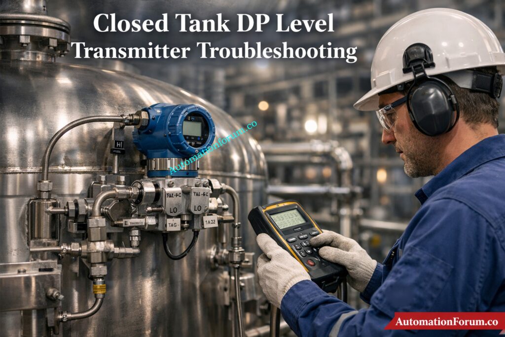
Introduction to Closed Tank DP Level Transmitter Troubleshooting
A closed tank DP level transmitter can show wrong, unstable, or fixed readings due to wet leg issues, dry leg problems, impulse line blockage, manifold valve errors, wiring faults, or PLC/DCS scaling mistakes. This step-by-step guide explains how to troubleshoot the problem in the correct order, starting from the process side and moving toward the transmitter and control system.
Troubleshoot Radar Level Issues Quickly: Step-by-Step Guide for Troubleshooting Radar Level Transmitters
Why a Closed Tank DP Level Transmitter Gives Wrong Readings
When a closed tank DP level transmitter gives a wrong reading, the problem is usually not “the transmitter” alone. In field practice, the fault can sit in the impulse lines, wet leg, dry leg, manifold valves, wiring, PLC/DCS scaling, analog input card, or transmitter configuration. That is why troubleshooting must follow a fixed sequence. A random approach often wastes time and creates new errors.
The safest and fastest method is to start from the process side, then move to the electrical side, then to the control system, and only after that suspect the transmitter hardware.
Master DP Calibration Like a Pro: Field Calibration Procedure for DP Level Transmitter
Safety First Before Troubleshooting a DP Level Transmitter
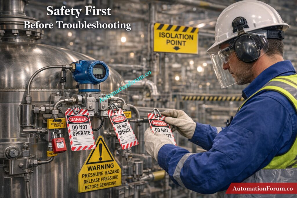
Before any inspection, isolate the loop and make the area safe.
- Apply LOTO.
- Confirm whether the tank is under pressure or vacuum.
- Depressurize impulse lines slowly.
- Open vent and drain points only after confirming safe conditions.
- Wear PPE suitable for the service fluid.
- Check whether the process contains hot, toxic, corrosive, or flammable material.
This step is important because many impulse line systems retain pressure even when the transmitter appears inactive. A wrong opening sequence can cause spray, exposure, or a sudden pressure release.
Fix DP Level Errors Fast: Troubleshooting of DP Type Level Transmitter
Step 1: Verify the Actual Tank Level
Do not trust the transmitter until you confirm the real process condition.
Methods to Confirm Actual Tank Level
Check the tank level using:
- sight glass
- local gauge
- dip measurement
- independent backup transmitter
- operator observation if available
Then compare the actual level with the DCS indication and the transmitter local display.
Sight Glass and Local Gauge Verification
Look at the nature of the error:
- always high
- always low
- fluctuating
- frozen
- slowly drifting
- reversing direction
Comparing DCS vs Field Indication
This first comparison tells you where the fault is likely sitting.
- Local display correct, DCS wrong → likely PLC/DCS, wiring, or analog input issue.
- Both local and DCS wrong → likely process side, manifold, impulse line, or transmitter issue.
- Reading changes only after maintenance → likely valve lineup, calibration, or wet leg problem.
Decode Boiler Drum Level Measurement: Understanding Boiler Drum Level Transmitters: Accurate DP Measurement Explained
Step 2: Check Power Supply and Loop Integrity
A DP transmitter cannot work correctly without a stable loop.
Power Supply and Loop Inspection Checklist
Inspect the following:
- 24 V DC supply
- loop continuity
- fuse or breaker status
- terminal tightness
- reverse polarity
- cable damage
- shield grounding
- moisture inside the junction box
- corrosion on terminals
- loose ferrules or broken conductors
Refer the below link for the Level Transmitter Selection Checklist for EPC Engineers – Step-by-Step Guide
24V DC Supply and Continuity Check
Typical symptoms help narrow it down:
- 0 mA output: Usually power loss, open loop, broken wire, reversed wiring, or transmitter electronics failure.
- 4 mA fixed output: May indicate no actual DP, equalizing valve open, or output held by configuration.
- 20 mA fixed output: This can mean saturation, the improper range, or a high DP condition.
- Unstable output: This is usually caused by weak wiring, a short circuit that happens sometimes, noise, or bad grounding.
Field tip: Check the loop current at the transmitter and see how it compares to the value in the control room. If the values don’t match, the problem is in the path that connects them.
Calibrate Level Devices With Confidence: Calibration Procedures for Level Measurement Devices
Step 3: Verify Wiring from Field to PLC/DCS
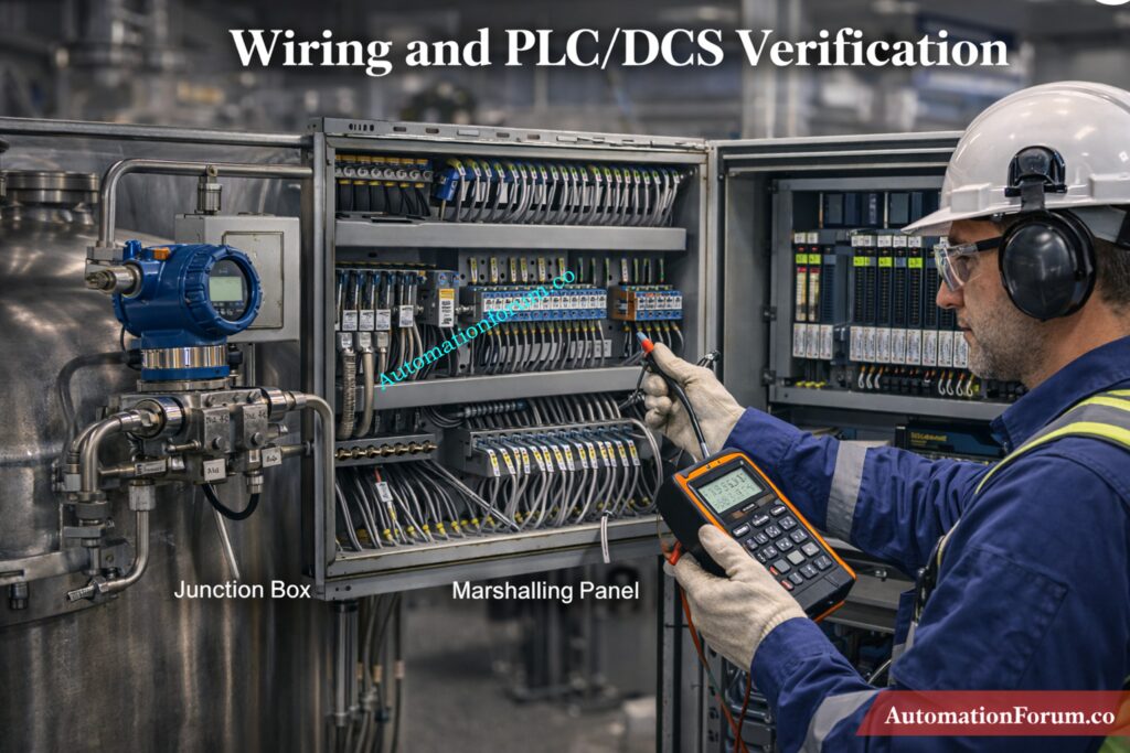
A large number of “instrument faults” are actually wiring or control system problems.
Complete Signal Path Verification
Trace the full signal chain:
- transmitter terminals
- junction box
- cable run
- marshalling cabinet
- barrier or isolator
- analog input module
- PLC or DCS tag
- SCADA or historian display
Junction Box to Marshalling Panel Checks
Check for these common issues:
- wrong terminal connection
- swapped polarity
- open circuit in cable
- short circuit between cores
- shield grounded at both ends incorrectly
- wrong cable pair used
- corroded terminal block
- damaged gland or water ingress
- wrong barrier wiring
- loose connection at marshalling
- analog input channel wired to the wrong transmitter
Common Wiring and Signal Issues in DP Transmitters
- Field transmitter reading is correct, PLC value is wrong
This usually means scaling, input card setup, or tag mapping error. - The output of the transmitter varies, but the PLC value stays the same.
- There could be a problem with the AI module, a broken loop, or the improper channel assignment.
Likely input module issue, grounding problem, or electrical noise entering the signal path. - No response in PLC even though transmitter is active
Check if the channel is mapped correctly and whether the I/O is healthy.
Stop Failures with PM Procedures: Collection of Preventive Maintenance (PM) Procedures for Instrumentation and Control Systems
Step 4: Check PLC / DCS Configuration and Scaling
If the wiring is healthy, the next suspect is the control system configuration.
Correct Analog Input and Scaling Configuration
Confirm the following:
- correct analog input channel
- correct tag name
- correct transmitter range
- correct LRV and URV
- correct engineering units
- proper 4–20 mA scaling
- no accidental reverse action
- no square root function enabled by mistake
- no simulation mode active
- no manual override or forced value
- AI card status is healthy
- no bad quality flag from the module
4-20 mA Scaling and Signal Conversion
- 4–20 mA transmitter configured as 0–10 V input
- mA input scaled as pressure instead of level
- wrong decimal placement
- wrong tank range entered
- tag linked to another transmitter
- output forced in the logic
- historian or SCADA showing old data
- filtering or damping too high
- bad raw count conversion
Raw Count vs Engineering Value Analysis
Look at both raw counts and engineering value.
- If raw counts change but the engineering value does not, the scaling logic is wrong.
- If raw counts do not change, the issue is probably wiring, input card, or transmitter output.
Unlock 15+ Level Calculators Now: 15+ Collection of Level Measurement Calculators for Industrial Instrumentation
Step 5: Check Manifold Valve Position
The manifold must be in the correct operating position.
Correct Manifold Valve Configuration
Normal arrangement:
- HP valve open
- LP valve open
- equalizing valve closed
Common Manifold-Related Errors
Also inspect for:
- partially closed root valve
- equalizing valve left open after maintenance
- leaking drain valve
- vent valve not closed properly
- internal valve passing
Symptoms of Incorrect Valve Position
- constant reading
- no response to actual level change
- offset reading
- low reading in a full tank
- high reading in an empty tank
Field tip: A transmitter with the equalizing valve left open often behaves like both sides are seeing the same pressure. That produces a very misleading reading and is one of the first checks to perform after maintenance.
Test Your Closed Tank Troubleshooting Skills: Can You Solve Closed Tank Level Measurement Failures? Advanced Instrumentation Troubleshooting Quiz
Step 6: Inspect the Impulse Lines

Impulse line blockage is one of the most common causes of bad DP level behavior in closed tanks.
Causes of Impulse Line Blockage
Check both HP and LP lines for:
- sludge
- rust
- scale
- wax
- slurry buildup
- polymer deposits
- crystals
- trapped liquid
- trapped gas
- kinks
- vibration damage
- cracked tubing
- leakage
- wrong slope
Symptoms of Blocked Impulse Lines
- Slow response → partial blockage
- Frozen reading → complete blockage or valve issue
- Drifting output → leak, temperature effect, or reference problem
- Fluctuating output → air pockets, vapor, or unstable process pressure
Field Diagnosis Tips for Impulse Line Issues
In liquid service, air pockets in the impulse line can distort the pressure seen by the transmitter. In gas service, liquid accumulation can create a false head.
Field tip: If tapping the impulse line causes the reading to change, suspect a partial blockage or sticky deposit inside the line.
Dry Calibrate Displacer Transmitters Easily: Displacer Level Transmitter Calibration Calculator for Dry Calibration Step by Step Guide
Step 7: Check Wet Leg and Dry Leg Condition
This is critical in closed tank level measurement.
Wet Leg Troubleshooting in Closed Tank Systems
- confirm the leg is actually filled
- inspect for leakage
- check evaporation loss
- verify stable condensate level
- check whether the reference liquid density changed
- inspect for plugging at the connection point
A wet leg problem often shows up as a false high reading, especially when the tank is empty or nearly empty.
Dry Leg Troubleshooting and Condensation Issues
- ensure the leg remains dry
- check for condensation
- inspect for liquid build-up
- confirm there is no blockage in the vapor line
A dry leg problem often causes a false low reading or unstable output.
Wet Leg vs Dry Leg Error Behavior
Wet leg empty = high reading error.
Dry leg filled = low reading error.
Choose Hybrid Level Methods Smarter: Hybrid Level Measurement Selection Procedure for EPC Instrumentation Engineers
Step 8: Check Density or Specific Gravity Changes
A DP transmitter does not measure level in isolation. It measures pressure caused by liquid head. If the fluid density changes, the level indication changes too.
Common Causes of Density Variation
Check for:
- temperature variation
- product composition change
- mixing or layering
- concentration changes
- slurry variation
- SG mismatch in the calculation
Symptoms of Density-Related Errors
- reading drifts with temperature
- transmitter looks fine, but indicated level is wrong
- readings differ between batches
- same level gives different output in different operating conditions
This is common in tanks where the product is not constant or where the process temperature changes significantly.
Challenge Your Drum Level Control Knowledge: Three Element Drum Level Control System – Advanced Quiz for Instrumentation Engineers
Step 9: Verify Calibration, Zero and Span

Once the process and wiring checks are complete, inspect calibration.
DP Transmitter Calibration Checks
Check:
- zero trim
- span trim
- LRV
- URV
- output linearity
- correct unit conversion
- correct level-to-pressure relationship
Common Calibration Mistakes
- zero shifted during maintenance
- wrong span entered
- transmitter ranged for the wrong tank height
- incorrect engineering units
- bad conversion from pressure to level
- transmitter not re-trimmed after reinstalling impulse lines
Best practice
Isolate the transmitter properly, apply known pressure values, and compare the current output to the expected result. Do not assume a replacement transmitter is calibrated correctly just because it is new.
Maximize Radar Level System Performance: Checklist for Best Radar Level Measurement & Control System Performance
Step 10: Check Transmitter Hardware
If all external checks are fine, then inspect the transmitter itself.
DP Transmitter Hardware Inspection
Look for:
- damaged sensor diaphragm
- blocked process port
- moisture ingress
- corroded terminals
- failed electronics
- unstable output after known calibration
- display failure
- internal diagnostic alarms
Symptoms of Hardware Failure
- no output change with applied DP
- output stuck at one value
- erratic signal despite stable process and wiring
- impossible zero or span correction
- communication failure in a smart device
Hardware should be the last suspect after process, piping, electrical, and system checks are cleared.
Calculate Wet Leg Levels Accurately: Wet-Leg Level Calculation for DP Transmitters: Complete Guide for Instrumentation Design Engineers
Step 11: Check Smart Communication and Diagnostics
For HART, Fieldbus, or other smart transmitters, the digital side can reveal problems that analog current alone will not show.
HART and Fieldbus Diagnostic Checks
Check:
- device tag
- process variable status
- diagnostics
- damping
- simulation mode
- fail mode
- write protection
- communication quality
- whether digital value matches analog output
Common Smart Communication Issues
- analog output correct, digital value wrong
- digital value correct, DCS still showing old data
- transmitter in simulation mode
- bad device status ignored in DCS
- communication fault mistaken for measurement fault
Get Open Tank Calculations Right: Open Tank Level Transmitter Calculator – Complete Guide for EPC Instrumentation Engineers

Diagnose DP Level Transmitter Problems by Symptom
| Symptom | Likely Cause |
| Transmitter shows high level when the tank is empty | Wet leg emptyLP reference lostManifold issueZero shift |
| Transmitter shows low level when the tank is full | HP impulse blockageDry leg condensationScaling errorWrong span |
| Reading fluctuates | Air or gas in impulse lineLoose wiringProcess pulsationPoor groundingUnstable pressure in the tank |
| Reading is constant | Equalizing valve openBlocked impulse lineTransmitter frozenPLC overrideInput card issue |
| There is no output | Power lossBroken loopWiring faultTransmitter electronics failure |
Refer the below link for the Hybrid Level Measurement: Capacitance + Guided Wave Radar (GWR) Technology
Final Troubleshooting Checklist for Closed Tank DP Level Transmitter

A practical, field-ready checklist designed to quickly diagnose wrong, fluctuating, or fixed level readings in closed tank DP transmitters.
This step-by-step guide helps engineers identify root causes from process issues to wiring, scaling, and transmitter faults using a structured troubleshooting approach.
Refer the below link to Download the Troubleshooting Checklist for Closed Tank DP Level Transmitter
FAQs on Closed Tank DP Level Transmitter Troubleshooting
Why does a closed tank DP transmitter show high level when the tank is empty?
This usually happens due to a wet leg empty condition, loss of LP reference pressure, manifold misalignment, or zero shift causing false differential pressure.
What happens if the wet leg is empty?
If the wet leg is empty, the transmitter sees reduced LP pressure, which makes it look like the tank is full even when it is empty.
Why does the transmitter reading stay fixed?
A fixed reading is usually caused by an open equalizing valve, a blocked impulse line, a frozen transmitter, a PLC override, or a problem with the input card.
How do you know if the impulse line is blocked?
When an impulse line is blocked, it might produce slow response, drifting, or readings that are entirely stuck and don’t change with real level changes.
Can density change affect DP level reading?
Yes, because DP transmitters sense the pressure of liquid heads, any change in density will alter how accurately the level measurement is.
Conclusion: Key Takeaways for Reliable DP Level Measurement
Troubleshooting a closed tank DP level transmitter is a structured job, not a guesswork job. The most common causes are not transmitter failure alone but installation, reference leg, wiring, scaling, or process-condition problems. A disciplined step-by-step approach reduces downtime, improves signal reliability, and prevents false level alarms from affecting plant operation.
Refer the below link for the Interface Level Measurement Selection Procedure – Complete 2025 Guide for Process Engineers