
- What Is Intrinsic Safety in Instrumentation Systems?
- What Do Ex ia, Ex ib and Ex ic Mean?
- How to Read the Complete Ex Instrument Marking
- What Is Ex ia Intrinsic Safety Protection?
- What Is Ex ib Intrinsic Safety Protection?
- What Is Ex ic Intrinsic Safety Protection?
- Ex ia vs Ex ib vs Ex ic: Main Differences
- Ex ia vs Ex ib vs Ex ic and Hazardous Area Zones
- Zener Barrier vs Galvanic Isolator for Intrinsic Safety
- Importance of Entity Parameters and Cable Parameters
- Practical Examples of Ex ia, Ex ib and Ex ic Selection
- Comparing Ex ia, Ex ib and Ex ic in Process Plants
- Common Ex ia, Ex ib and Ex ic Selection Mistakes
- How to Select the Correct Ex ia, Ex ib or Ex ic Instrument
- Ex ia, Ex ib and Ex ic Installation and Maintenance
- What Happens When an Intrinsically Safe Loop Is Modified
- Key Takeaway for Instrumentation Engineers
- Frequently Asked Questions About Ex ia, Ex ib and Ex ic
- Conclusion: Key Takeaway for Instrumentation Engineers
An instrumentation engineer working in a refinery may come across three transmitters that look almost identical. One is marked Ex ia, another is Ex ib, and the third is Ex ic. All three use intrinsic safety, yet they are not automatically interchangeable.
This is a common point of confusion during instrument selection, commissioning, maintenance, and replacement.
For process plants, understanding this distinction is important because selecting an instrument only by its general Ex marking can lead to an incorrect installation.
What Is Intrinsic Safety in Instrumentation Systems?
How Does Intrinsic Safety Prevent Ignition?
Intrinsic safety is a protection concept that limits the electrical and thermal energy available in a circuit so that the circuit cannot become an ignition source under the specified conditions.
The concept is particularly useful for low power instrumentation circuits. Instead of containing an explosion, intrinsic safety is designed to prevent the electrical circuit from producing enough energy to ignite the surrounding atmosphere.
Where Is Intrinsic Safety Used in Process Industries?
Typical applications include pressure transmitters, temperature transmitters, level transmitters, flow transmitters, gas detectors, switches, valve position feedback circuits, remote input signals, and other field instrumentation.
Why Are Intrinsically Safe Instrumentation Loops Used?
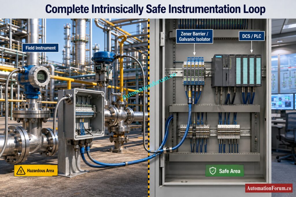
In a typical installation, the field instrument is connected to an associated apparatus such as a Zener barrier or galvanic isolator. The complete circuit must be evaluated rather than considering the field instrument by itself.
IEC 60079 11 specifies requirements for intrinsically safe apparatus and associated apparatus connected to intrinsically safe circuits entering explosive atmospheres.
Catch Critical SIS Compliance Gaps Before Inspection Day: Advanced Safety Instrumented System (SIS) Inspection Checklist for IEC 61511 Compliance
What Do Ex ia, Ex ib and Ex ic Mean?
The letters ia, ib and ic represent different levels of intrinsic safety protection.
The important distinction is not simply the physical construction of a barrier or the number of components inside it. The protection level results from the applicable design requirements, testing, fault assessment, and certification.
What Is the Difference Between Ex ia, Ex ib and Ex ic?
In practical terms, the three levels can be understood as follows.
- Ex ia provides the highest level of protection among these three levels.
- Ex ib provides a lower level of fault tolerance than Ex ia.
- Ex ic is intended for applications where the hazardous atmosphere is expected less frequently and provides a lower level of protection than Ex ia and Ex ib.
Refer the below link for the Top Causes of Intrinsically Safe (IS) Loop Failure and How to Avoid Them
How to Read the Complete Ex Instrument Marking
- One of the most important points when selecting hazardous area instrumentation is that Ex ia, Ex ib or Ex ic is only one part of the complete equipment marking.
- An instrument may have a marking that contains several different elements. These can identify the protection concept, protection level, gas group, temperature class, equipment protection level, equipment category, and other certification information.
- For example, an instrumentation engineer may see an Ex marking on a pressure transmitter and focus only on the Ex ia portion. However, the rest of the marking can be equally important for determining whether the transmitter is suitable for the intended location.
- The gas group must be compatible with the hazardous atmosphere. The temperature class must also be suitable for the maximum surface temperature permitted for the application.
- Ambient temperature limitations may also apply. Some certified instruments can only be used within a specified ambient temperature range.
- Certificate limitations and special conditions of use must not be ignored. These conditions may specify installation requirements, mechanical protection, cable entry requirements, or other restrictions that must be satisfied.
- This is why equipment selection should always be based on the complete certified marking rather than only looking for the letters Ex ia, Ex ib or Ex ic.
Master Hazardous Area Installation Rules Without The Confusion: IEC 60079-14 Explained: Complete Guide to Hazardous Area Installation for Instrumentation and Control Systems
What Is Ex ia Intrinsic Safety Protection?
Ex ia provides the highest intrinsic safety protection level among Ex ia, Ex ib and Ex ic.
Its design considers normal operation together with specified combinations of two countable faults. This makes it suitable for applications where the possibility of an explosive atmosphere is significant and a high level of protection is required.
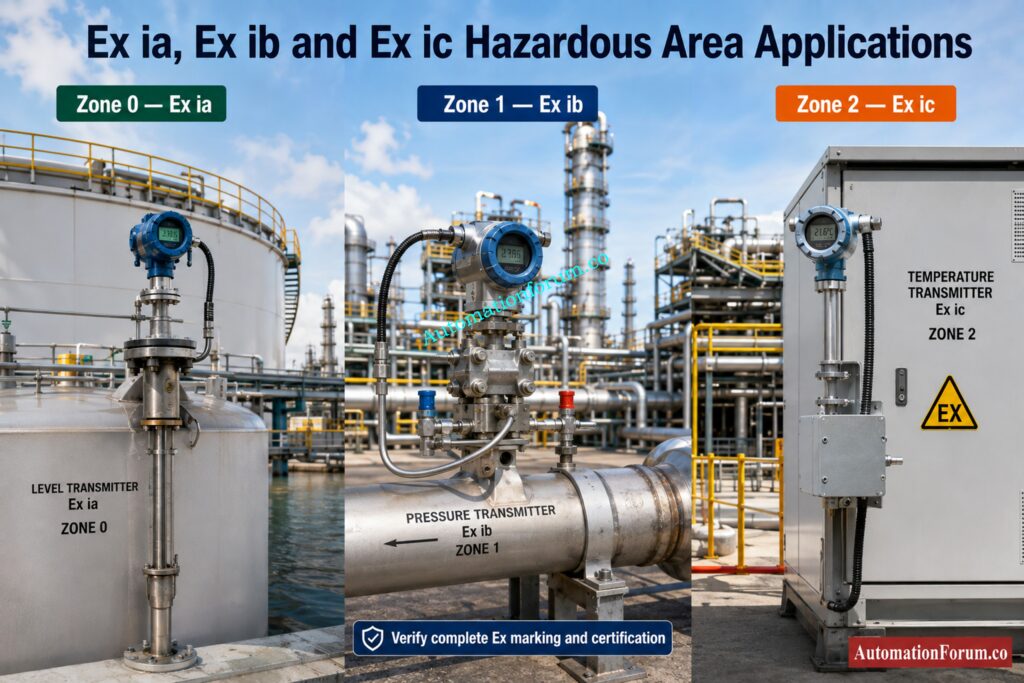
Ex ia is commonly associated with Zone 0 applications for gas atmospheres.
Consider a level transmitter installed on a process vessel where an explosive gas atmosphere can be continuously present or present for long periods. If the hazardous area classification requires equipment suitable for Zone 0, an Ex ia certified instrument may be considered, provided its complete marking and certificate satisfy the installation requirements.
An important point is that Ex ia equipment may also be used in less hazardous locations when the complete certification and installation conditions permit it.
Discover Which Certification Really Fits Your Hazardous Area: ATEX vs IECEx Certification: Complete Guide for Hazardous Area Instrumentation
What Is Ex ib Intrinsic Safety Protection?
Ex ib provides intrinsic safety protection under normal operation and one specified countable fault.
It is commonly associated with Zone 1 applications.
For example, consider a pressure transmitter installed near a process unit where an explosive atmosphere may occur during normal plant operation. If the hazardous area classification identifies the location as Zone 1, an appropriately certified Ex ib instrument may be suitable.
Ex ib should not be viewed simply as a cheaper version of Ex ia. The selection should come from the hazardous area classification, required protection level, certified equipment, and complete loop design.
The correct question is not which instrument has the highest protection. The correct question is which certified protection level satisfies the actual installation requirement.
See Why IS Protection Remains A Safer Choice: Why Choose Intrinsic Safety (IS) for Hazardous Area Instrumentation?
What Is Ex ic Intrinsic Safety Protection?
Ex ic is a certified intrinsic safety protection level intended primarily for Zone 2 applications.
Its assessment is based on normal operating conditions and has less stringent fault tolerance requirements than Ex ia and Ex ib.
This does not mean that Ex ic has no safety design. It remains a defined and certified protection concept. The difference is the level of protection and the fault assumptions applied during assessment.
For example, a temperature transmitter installed in a Zone 2 area may use Ex ic protection when the equipment certification, area classification, gas group, temperature class, and installation requirements all support that selection.
Ex ic should not automatically be considered suitable for Zone 0 or Zone 1 simply because it carries an intrinsic safety marking.
Fix Field And Control Room Signal Discrepancies Fast: Loop Checking Field vs Control Room Reading Mismatch Explained
Ex ia vs Ex ib vs Ex ic: Main Differences
Ex ia vs Ex ib vs Ex ic Hazardous Area Applications
| Parameter | Ex ia | Ex ib | Ex ic |
| Protection level | Highest of the three | Intermediate | Lower than ia and ib |
| Fault assessment | Normal operation and specified two fault conditions | Normal operation and specified one fault condition | Normal operating conditions with less stringent fault assumptions |
| Typical application | Zone 0 | Zone 1 | Zone 2 |
| Typical instrumentation | Critical vessel and tank measurement | Process unit instrumentation | Zone 2 field instrumentation |
| Protection requirement | Highest | Intermediate | Lower |
| Selection basis | Area classification and complete certification | Area classification and complete certification | Area classification and complete certification |
| Maintenance | Strict certificate and loop verification | Strict certificate and loop verification | Certificate and loop verification remain important |
The table provides a useful general comparison, but it should not be used as the only basis for equipment selection.
The complete Ex marking must also be checked. This can include the gas group, temperature class, equipment protection level where applicable, ambient conditions, certificate limitations, and special conditions of use.
Prove Your Safety Integrity Level With Greater Confidence: SIL Verification Report (Safety Integrity Level Verification Report)
Ex ia vs Ex ib vs Ex ic and Hazardous Area Zones
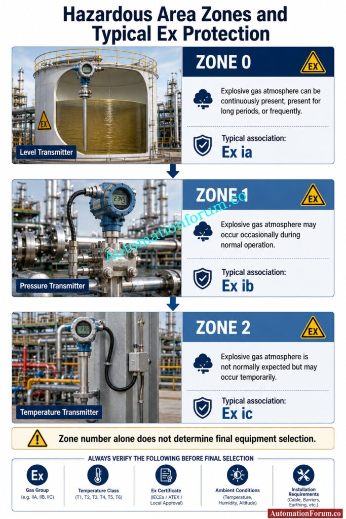
- Zone 0 is an area where an explosive gas atmosphere is present continuously, for long periods, or frequently.
- Zone 1 is an area where an explosive gas atmosphere is likely to occur occasionally during normal operation.
- Zone 2 is an area where an explosive gas atmosphere is not likely during normal operation, but if it occurs, it exists only for a short period.
- This creates the commonly used relationship of Ex ia with Zone 0, Ex ib with Zone 1, and Ex ic with Zone 2.
- However, engineers should not select an instrument from the zone number alone.
- The hazardous area drawing, instrument data sheet, equipment certificate, complete Ex marking, gas group, temperature class, ambient conditions, and installation requirements must all be reviewed.
Strengthen SIS Inspection Readiness Before Compliance Audits: Advanced Safety Instrumented System (SIS) Inspection Checklist for IEC 61511 Compliance
Zener Barrier vs Galvanic Isolator for Intrinsic Safety
An intrinsic safety loop normally includes more than the field instrument.
A Zener barrier or galvanic isolator may be installed between the safe area control system and the hazardous area instrument.
The purpose is to restrict the electrical energy that can reach the hazardous area circuit. Depending on the design, the associated apparatus can limit voltage, current, power, or stored energy.
A Zener barrier typically depends on Zener protection, current limiting, fusing, and an appropriate earth arrangement. A galvanic isolator provides electrical isolation and uses an internal circuit designed to maintain the required intrinsic safety characteristics.
The important engineering point is that the protection level of the complete loop cannot be assumed from the transmitter alone.
The field instrument, associated apparatus, cable, connectors, and installation arrangement can all affect the intrinsic safety assessment.
Refer the below link for the Understanding Zener vs Galvanic Isolation in IS Loops for 4 to 20 mA Systems
Importance of Entity Parameters and Cable Parameters
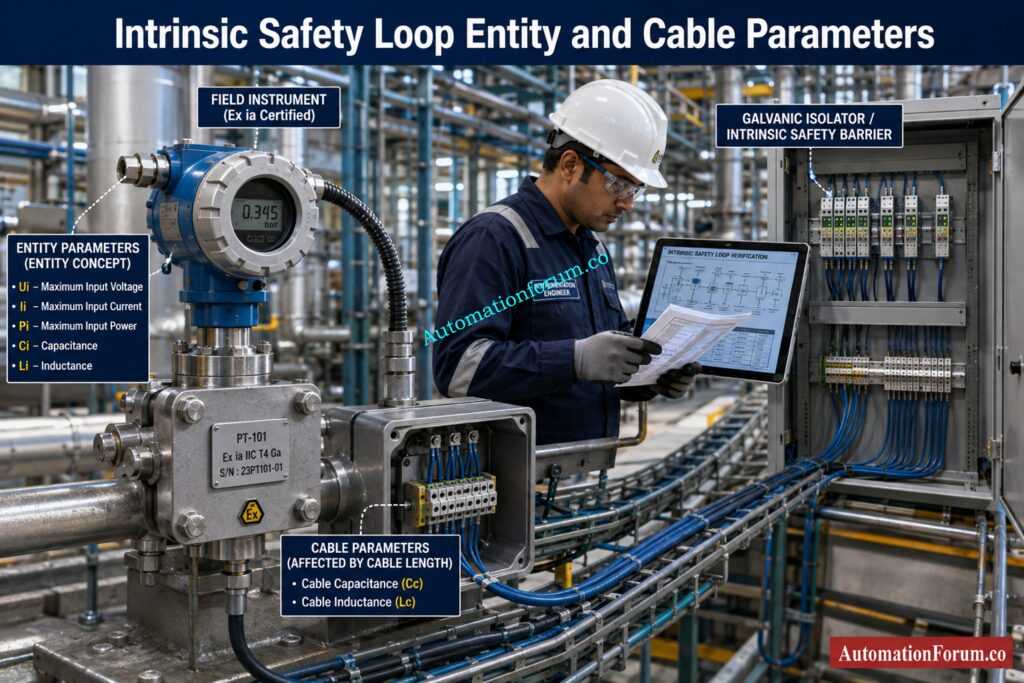
Intrinsic safety loop verification depends on parameters specified by the equipment manufacturer.
Important values can include maximum input voltage, maximum input current, maximum input power, capacitance, and inductance.
Cable characteristics are also important.
A long cable can introduce significant capacitance and inductance into an intrinsically safe circuit. If the cable parameters exceed the permitted values of the equipment combination, the original loop verification may no longer be valid.
This is particularly important during plant modification work. Replacing a cable with another type, increasing cable length, or changing a barrier can require the intrinsic safety assessment to be reviewed.
Engineers should therefore avoid treating cable selection as an ordinary wiring decision when working with intrinsically safe circuits.
Refer the below link for the Intrinsic Safety Entity Parameter Calculator for Reliable Hazardous Area Loop Design
Practical Examples of Ex ia, Ex ib and Ex ic Selection
Consider three transmitters installed at different locations in a process plant. Although all three instruments may perform similar measurement functions, the hazardous area classification at each location can be different. This directly affects the required intrinsic safety protection level.
Ex ia Example in a Zone 0 Tank Application
Consider a pressure or level transmitter installed on a storage tank containing a flammable hydrocarbon.
The area inside or immediately associated with the tank may be classified as Zone 0 when an explosive gas atmosphere can be continuously present, present for long periods, or occur frequently.
In this type of application, an Ex ia certified transmitter may be selected because Ex ia provides the highest intrinsic safety protection level among Ex ia, Ex ib and Ex ic.
Typical examples include level transmitters installed on hydrocarbon storage tanks, pressure transmitters connected to vessels, temperature sensors installed in process vessels, and certain analytical instruments located where Zone 0 requirements apply.
For example, imagine a level transmitter installed on a crude oil storage vessel. The transmitter is connected through an approved intrinsic safety barrier or galvanic isolator to the control system in the safe area.
The engineer should not simply check whether the transmitter says Ex ia. The complete marking must also be checked for the required gas group, temperature class, ambient conditions, and certificate limitations.
The associated apparatus must also be compatible with the transmitter entity parameters. Cable capacitance and inductance must be considered as part of the intrinsic safety loop verification.
This is why Ex ia is commonly considered when the field installation has the highest hazardous area protection requirement.
Verify Live 4 To 20 mA Signals Without Guesswork: Live Signal Verification 4 to 20 mA Loop Standard Operating Procedure (SOP)
Ex ib Example in a Zone 1 Process Area
Now consider a pressure transmitter installed on a process pipeline inside a refinery process unit.
The transmitter may be located in an area where a flammable gas atmosphere can occur during normal plant operation. This type of location may be classified as Zone 1.
An appropriately certified Ex ib transmitter may be selected for this application when the equipment certification and project requirements support it.
Typical examples can include pressure transmitters on hydrocarbon process lines, differential pressure transmitters used for flow measurement, temperature transmitters installed near process equipment, level transmitters on process vessels, and switches installed in Zone 1 areas.
For example, consider a differential pressure transmitter measuring flow through a hydrocarbon pipeline. The transmitter is installed in a Zone 1 area and connected to a control system through a certified galvanic isolator.
The engineer would first confirm the hazardous area classification and then verify the transmitter Ex marking and certificate. The gas group and temperature class must match the process area requirements.
The galvanic isolator must also be suitable for the transmitter and the intended intrinsic safety circuit.
Ex ib should therefore not be treated as simply a lower cost alternative to Ex ia. Its selection should be based on the actual hazardous area classification and the required protection level.
Check Barrier Earth Fault Risks Before They Cause Trouble: IS Barrier Earth Fault Current Calculator | Intrinsic Safety Loop Design Tool
Ex ic Example in a Zone 2 Process Area
Now consider an instrument installed in an area where an explosive gas atmosphere is not expected during normal plant operation, but could occur for a short period if an abnormal condition develops.
This type of location may be classified as Zone 2.
An Ex ic certified instrument may be appropriate for such an installation when the complete certification and project requirements permit its use.
Typical examples can include temperature transmitters, pressure transmitters, flow instruments, valve position feedback devices, and other low power instrumentation installed in Zone 2 areas.
For example, consider a temperature transmitter installed near a utility or process area where flammable gas is not normally present but could reach the instrument during an unusual release.
If the area is classified as Zone 2, an Ex ic instrument may be selected after checking the equipment certificate and complete Ex marking.
The engineer must still verify the gas group, temperature class, ambient temperature range, certificate limitations, and associated apparatus requirements.
Ex ic should not be treated as an unprotected instrument. It is still a certified intrinsic safety protection concept. Its intended application simply has different protection and fault assessment requirements compared with Ex ia and Ex ib.
Understand IS Protection Levels Before Selecting Equipment: Intrinsic Safety Protection Systems: Understanding Ex ia, Ex ib, and Ex ic
Comparing Ex ia, Ex ib and Ex ic in Process Plants
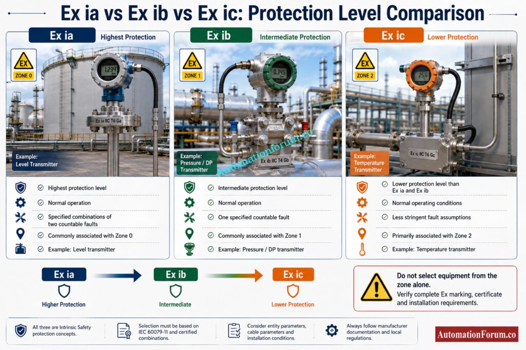
The difference becomes easier to understand when the three examples are considered together.
| Plant location | Typical hazardous condition | Typical protection level | Example instrument |
| Zone 0 tank or vessel area | Explosive atmosphere can be continuously present or present for long periods | Ex ia | Level transmitter |
| Zone 1 process unit | Explosive atmosphere can occur during normal operation | Ex ib | Pressure or differential pressure transmitter |
| Zone 2 process area | Explosive atmosphere is not normally expected but may occur temporarily | Ex ic | Temperature transmitter or valve position feedback |
These are typical engineering associations rather than a substitute for checking the equipment certificate and project requirements.
What Should Engineers Check Before Selecting Ex Equipment?
Suppose an EPC engineer receives three instrument data sheets for the above applications. The selection process should begin with the hazardous area classification drawing.
The engineer should identify the zone and then check the required gas group and temperature class.
Next, the instrument Ex certificate should be reviewed. The complete Ex marking must be suitable for the classified location.
The associated apparatus should then be checked. This may be a Zener barrier or a galvanic isolator depending on the approved loop design.
The engineer should compare the entity parameters of the field instrument and associated apparatus. These include maximum voltage, current, power, capacitance, and inductance.
Cable parameters should also be checked because cable capacitance and inductance can affect the intrinsic safety assessment, particularly when long cable runs are involved.
Finally, the engineer should verify the loop drawing, installation arrangement, certificate limitations, special conditions of use, project specifications, and applicable standards.
Avoid Costly Cable Mistakes Across ATEX Hazardous Zones: Intrinsically Safe Cables for ATEX Zones – Complete Checklist for EPC Engineers
Why Can the Same Transmitter Not Be Used Everywhere?
A common field assumption is that if a transmitter is intrinsically safe, it can be installed anywhere in the hazardous area.
That assumption is incorrect.
An Ex ic transmitter cannot automatically replace an Ex ia transmitter in a Zone 0 application. Similarly, an Ex ib transmitter should not automatically be installed in Zone 0 simply because it is also an intrinsic safety device.
The hazardous area classification establishes the required protection level. The instrument certificate then confirms whether the selected equipment satisfies that requirement.
The complete loop must also remain compatible after installation.
This is particularly important during maintenance. If an Ex ia transmitter is replaced with another transmitter having the same process connection, measuring range, and output signal, the replacement is not necessarily acceptable. Its Ex certification and entity parameters may be different.
The same principle applies when replacing a barrier or galvanic isolator.
This is the practical difference between simply selecting an instrument and properly engineering an intrinsically safe loop.
Test Your Intrinsic Safety Knowledge Like A Specialist: Advanced Quiz on Intrinsic Safety Instrumentation Circuits in Oil & Gas Process Industries
Common Ex ia, Ex ib and Ex ic Selection Mistakes
One common mistake is assuming that every Ex i instrument can be installed in every hazardous zone.
Another mistake is checking only the transmitter certificate while ignoring the associated apparatus.
Engineers sometimes overlook entity parameter compatibility or cable capacitance and inductance.
Another frequent mistake is assuming that Ex ia, Ex ib and Ex ic are determined simply by the number of Zener diodes inside a barrier. The protection level is based on applicable standard requirements, testing, fault assessment, circuit design, and certification.
Confusing intrinsic safety with flameproof protection or increased safety protection can also result in incorrect equipment selection.
During maintenance, replacing an approved barrier or transmitter with a similar looking model can create a compliance problem if the replacement has different entity parameters or certificate limitations.
Changing cable length without reviewing the intrinsic safety calculation is another issue that can easily be missed during plant modifications.
Choose The Right Cable Gland Before Installation Starts: Cable Gland Selection for Hazardous Area Installations – Complete 2025 Guide
How to Select the Correct Ex ia, Ex ib or Ex ic Instrument
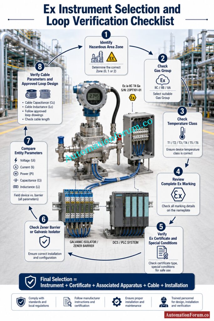
A practical selection process should begin with the hazardous area classification.
First identify the zone.
Then check the gas group and temperature class.
Next confirm the required equipment protection level where applicable.
Review the instrument Ex marking and certificate. Check certificate limitations and special conditions of use.
Then verify the associated apparatus, such as the Zener barrier or galvanic isolator.
Compare the entity parameters of the field instrument with those of the associated apparatus.
Check cable capacitance and inductance.
Finally, verify the loop drawing, installation requirements, project specifications, client requirements, and applicable standards.
IEC 60079 11 remains the key standard for equipment protection by intrinsic safety, while IEC 60079 14 addresses electrical installation design, selection, and erection for explosive atmospheres.
Know Which Cable Type Your Hazardous Loop Really Needs: Difference Between Intrinsically Safe (IS) and Non-IS Cables
Ex ia, Ex ib and Ex ic Installation and Maintenance
Correct wiring and identification are important for intrinsically safe circuits. Segregation from non intrinsically safe circuits must also be maintained according to the approved installation design.
Earthing requirements should not be treated as one universal rule. A Zener barrier and a galvanic isolator can have different installation requirements.
The approved loop design and manufacturer documentation should always be followed.
During maintenance, do not select a replacement transmitter simply because it has the same measurement range and process connection.
The Ex marking, certificate, entity parameters, temperature class, gas group, ambient rating, and associated apparatus compatibility must also be checked.
Good documentation is especially important because a loop that was compliant during commissioning can become non compliant after an unverified modification.
Understand The Critical Difference Between IS And Explosion Protection: Difference Between Intrinsically Safe and Explosion-Proof
What Happens When an Intrinsically Safe Loop Is Modified
Plant modifications can create problems when engineers focus only on the process measurement requirement.
For example, a new control room may be installed farther from an existing field instrument. The engineering team may decide to use a longer cable.
From the signal transmission point of view, the longer cable may work perfectly.
However, the additional cable length increases the distributed capacitance and inductance of the circuit.
The original intrinsic safety calculation may therefore need to be reviewed.
The same situation can occur when replacing a Zener barrier with a galvanic isolator, changing the transmitter model, modifying the termination arrangement, or changing cable type.
A modification that appears electrically simple can have implications for the intrinsic safety design.
For this reason, intrinsic safety documentation should be treated as controlled engineering documentation rather than ordinary wiring information.
Master FISCO Concepts Before Designing Fieldbus IS Networks: Fieldbus Intrinsically Safe Concept (FISCO) Model for Foundation Fieldbus H1 and Profibus PA
Key Takeaway for Instrumentation Engineers
When reviewing an intrinsically safe instrument, an engineer can follow a simple sequence.
Start with the hazardous area classification drawing and identify the zone.
Then identify the gas group and temperature requirements.
Check the complete Ex marking on the proposed instrument.
Check the equipment certificate for special conditions or limitations.
Check the associated apparatus and confirm that the interface is approved for the intended intrinsic safety circuit.
Compare the entity parameters of the field instrument and associated apparatus.
Check the capacitance and inductance of the cable.
Check loop drawing and termination layout.
Finally, confirm that the installation satisfies the project specification, manufacturer instructions, applicable standards, and approved hazardous area documentation.
This approach reduces the possibility of selecting an instrument that appears correct on paper but does not satisfy the complete loop requirements.
Frequently Asked Questions About Ex ia, Ex ib and Ex ic
What is the main difference between Ex ia, Ex ib and Ex ic?
The distinction between Ex ia, Ex ib and Ex ic is the amount of intrinsic safety protection and the fault situations evaluated at the time of certification. The Ex ia is the greatest level of protection, followed by Ex ib and Ex ic.
Can Ex ia equipment be used in Zone 1 and Zone 2?
Yes, Ex ia equipment can usually be used in Zone 1 and Zone 2, providing it is fully Ex certified and the gas group, temperature class and installation requirements are appropriate.
Can Ex ib equipment be used in Zone 0?
No, Ex ib is for Zone 1 applications, Zone 0 usually needs the higher degree of protection given by suitably approved Ex ia equipment.
Is Ex ic suitable for Zone 1?
Ex ic is primarily intended for Zone 2 hazardous areas and should not normally be selected for Zone 1. Always verify the complete Ex certificate and equipment marking before installation.
Does Ex ia mean the instrument is safe regardless of the barrier?
No, Ex ia does not make the instrument safe regardless of the barrier. The whole intrinsic safety loop comprising the accompanying apparatus, entity parameters, cable characteristics and installation must be checked.
What should be checked before replacing an intrinsically safe transmitter or barrier?
Verify the full Ex marking, certificate, gas group, temperature class, entity parameters, cable parameters, ambient limitations and certificate conditions before replacing the transmitter or the barrier.
What does Ex ia mean?
Ex ia means intrinsic safety with a high level of protection, designed to remain safe under normal operation and specified combinations of two countable faults. It is commonly associated with Zone 0 applications.
What is gas group IIA, IIB and IIC?
The explosive gasses are classified by gas groups according to their ignition properties and severity. IIC is the most stringent . IIA is the least demanding and IIB is somewhere in the middle . Equipment marked IIC is generally acceptable for IIA and IIB gasses , if other conditions are met .
What is the difference between intrinsically safe and explosion proof?
Intrinsic safety limits the electrical energy to avoid ignition, while explosion proof or flameproof protection uses a specially-designed enclosure to confine an internal explosion and prevent flame propagation.
What is the difference between Ex d and Ex i?
Ex d is flameproof protection based on containment, whereas Ex i is intrinsic safety based on limiting electrical and thermal energy. Ex i also requires proper verification of the complete field circuit.
What does Ex d stand for?
Ex d Flameproof enclosure protection Ex d protection means that the equipment enclosure is designed to survive an internal explosion and to prevent the flame from the internal explosion from igniting the surrounding hazardous atmosphere.
What are the IEC 60079 standards?
The IEC 60079 series is a family of international standards covering electrical equipment and installations for explosive atmospheres, including hazardous area classification, intrinsic safety, flameproof protection, installation, inspection, and maintenance.
Conclusion: Key Takeaway for Instrumentation Engineers
Ex ia provides the highest level among the three and is commonly associated with Zone 0. Ex ib is commonly associated with Zone 1, while Ex ic is primarily associated with Zone 2.
However, engineers should never select equipment simply by looking at ia, ib or ic.
A safe and compliant selection requires the hazardous area classification, complete equipment marking, certificate, gas group, temperature class, associated apparatus, entity parameters, cable characteristics, installation conditions, and approved loop design to be considered together.
The easiest way to remember the practical difference is to think of Ex ia, Ex ib and Ex ic as different intrinsic safety protection levels rather than simply three labels printed on instruments.
Ex ia is generally associated with the highest hazardous area requirement and is commonly used for Zone 0 applications.
Ex ib is generally associated with Zone 1 applications where a hazardous atmosphere can occur during normal plant operation.
Ex ic is generally associated with Zone 2 applications where an explosive atmosphere is not expected during normal operation but may occur temporarily.
However, the zone alone does not determine the final instrument selection.
The engineer must verify the complete Ex marking, certificate, gas group, temperature class, associated apparatus, entity parameters, cable characteristics, installation conditions, and project requirements.
Refer the below link for the Intrinsic Safe Calculation for Instrumentation Design Engineers
