
- Understanding PLC Analog Output Wiring for 4 to 20 mA and 0 to 10 V Signals
- What Is a PLC Analog Output Module and How Does It Work?
- 4 to 20 mA vs 0 to 10 V PLC Analog Output
- PLC 4 to 20 mA Analog Output Wiring Procedure
- PLC 0 to 10 V Analog Output Wiring Procedure
- PLC Analog Output Commissioning Procedure and Checklist
- PLC Analog Output Wiring Problems and Troubleshooting
- Important Precautions for PLC Analog Output Wiring
- Frequently Asked Questions About PLC Analog Output Wiring
- Final Recommendations for PLC 4 to 20 mA and 0 to 10 V Wiring
Understanding PLC Analog Output Wiring for 4 to 20 mA and 0 to 10 V Signals
PLC analog output wiring is an important part of industrial automation because it allows a programmable logic controller to regulate field equipment using continuously variable electrical signals.
In process plants, PLC analog outputs are commonly used to control valve positioners, variable frequency drives (VFDs), motor speed references, dampers and modulating actuators.
The two commonly used output signals are 4 to 20 mA current and 0 to 10 V voltage. Although both signals perform similar control functions, their wiring arrangements, electrical characteristics and application requirements are different.
Understanding the correct PLC analog output wiring procedure helps engineers avoid incorrect connections, signal fluctuations, output channel faults and commissioning delays.
What Is a PLC Analog Output Module and How Does It Work?
A PLC analog output module converts digital values generated by the PLC program into proportional electrical signals.
For example, when a PLC program commands a control valve to open by 50%, the analog output module generates 12 mA using a 4 to 20 mA output range.
Similarly, a 50% speed reference using a 0 to 10 V output produces 5 V.
Unlike digital outputs, which provide discrete ON and OFF states, analog outputs provide continuously variable signals.
Common output terminals include:
- AO+ for positive analog output.
- AO minus or channel common for the signal return.
- COM for the designated common connection.
- Functional earth for shielding arrangements, where provided.
Terminal names and channel arrangements vary between manufacturers. Some modules also provide galvanically isolated output channels.
Refer the below link for the Why not use 0-20mA & 0-15psi instead of 4-20mA & 3-15psi?
4 to 20 mA vs 0 to 10 V PLC Analog Output
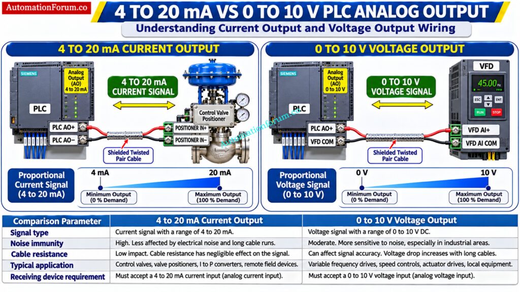
| Parameter | 4 to 20 mA | 0 to 10 V |
| Signal type | Current | Voltage |
| Noise immunity | Generally higher | More sensitive |
| Cable resistance | Limited by loop compliance | Affects voltage accuracy |
| Cable distance | Suitable for longer runs | Generally suited to shorter runs |
| Fault identification | Below 4 mA can indicate a fault | 0 V can be a valid command or fault |
| Typical application | Control valve positioner | VFD speed reference |
| Receiver requirement | Compatible current input | Compatible voltage input |
The 4 to 20 mA signal is generally preferred for process instrumentation because it offers better resistance to electrical interference and is less affected by cable resistance, provided the output remains within its compliance voltage and load limits.
The 0 to 10 V signal is commonly used for shorter connections where the receiving equipment provides a suitable high impedance input.
There is no universal maximum cable distance. The actual distance depends on cable characteristics, receiver impedance, output specifications and installation conditions.
Unlock Accurate HART Communication With This Powerful Engineering Tool: Advanced HART Loop Calculator for Reliable 4 to 20 mA and HART Communication
PLC 4 to 20 mA Analog Output Wiring Procedure
The 4 to 20 mA analog output is commonly used to control field instruments such as control valve positioners, VFDs and modulating actuators. Before wiring, verify whether the PLC analog output module provides an internally powered current output or requires an external 24 VDC supply.
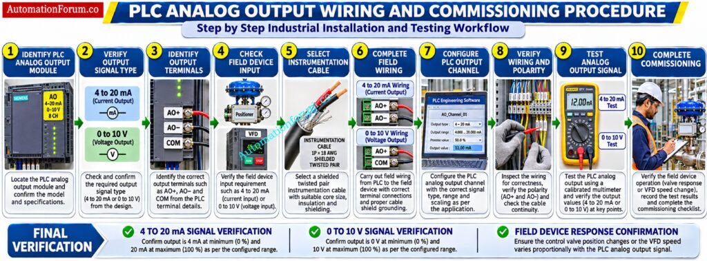
Step 1: Identify the PLC Analog Output Module
Check the PLC analog output module model and identify the channel intended for the field device. Verify that the selected channel supports a 4 to 20 mA current output.
Step 2: Verify the PLC Current Output Type
Check the manufacturer’s wiring diagram to determine whether the output is internally powered or externally powered.
An internally powered output provides the required loop energy from the PLC module. An externally powered arrangement requires a suitable external DC supply to complete the current loop.
Discover the Signal Selection Advantage Behind Reliable Industrial Control: Why 4-20 mA Current Signal is Preferred Over Voltage Signal in Instrumentation?
Step 3: Identify the PLC Analog Output Terminals
Identify the following terminals from the module wiring diagram:
- AO+ for current output positive.
- AO minus or designated return terminal.
- External supply terminals, where required.
Do not assume that all PLC modules use the same terminal arrangement.
Step 4: Check the Field Device 4 to 20 mA Input
Verify that the field device supports a 4 to 20 mA analog input. Check its input impedance, permitted signal range and wiring requirements.
Convert Current Readings Into Accurate Process Measurements Instantly: 4 to 20 mA Transmitter Output Process Value Calculator
Step 5: Select the Shielded Instrumentation Cable
Use suitable shielded twisted pair instrumentation cable. Maintain proper separation from motor cables, VFD output cables and other electrical power wiring.
Step 6: Connect the PLC 4 to 20 mA Output to the Field Device
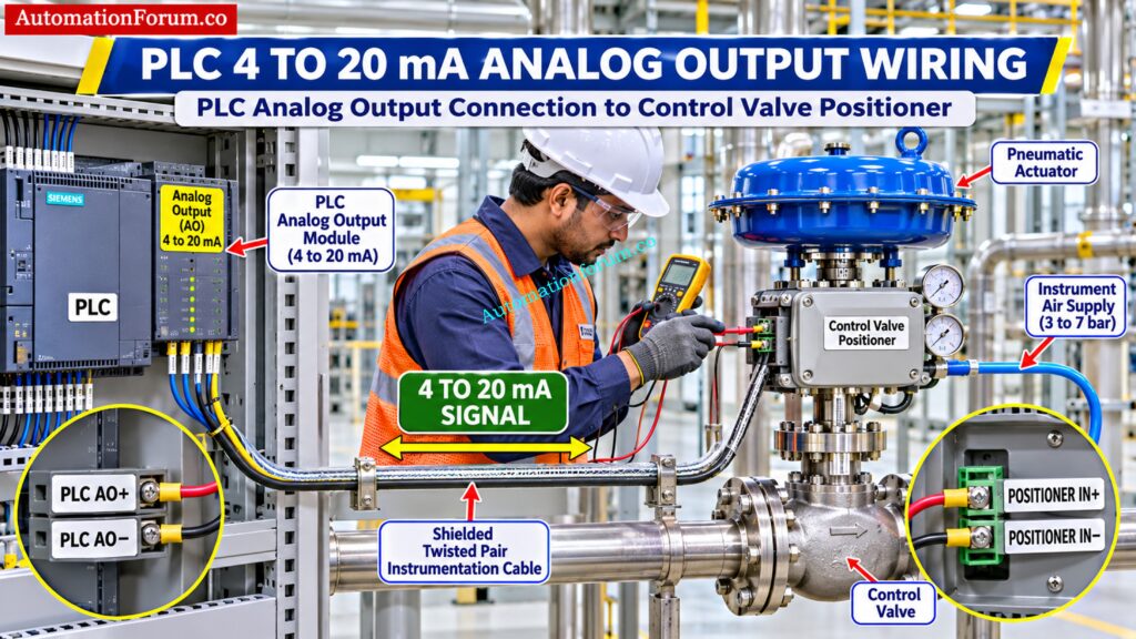
For an internally powered current output, the typical connection is:
Connect the positive output to the positive input and the return terminal to the corresponding negative input.
Transform Drive Frequency Values Into Precise Control Signals: Frequency(Hz) to 4 to 20 mA Signal Conversion Calculator
Step 7: Connect an External 24 VDC Supply for Passive Output
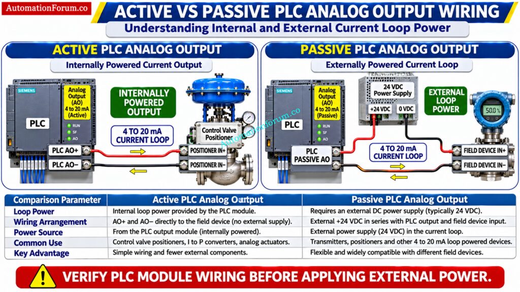
For a passive PLC output, an external 24 VDC supply may be required.
A typical functional loop arrangement is:
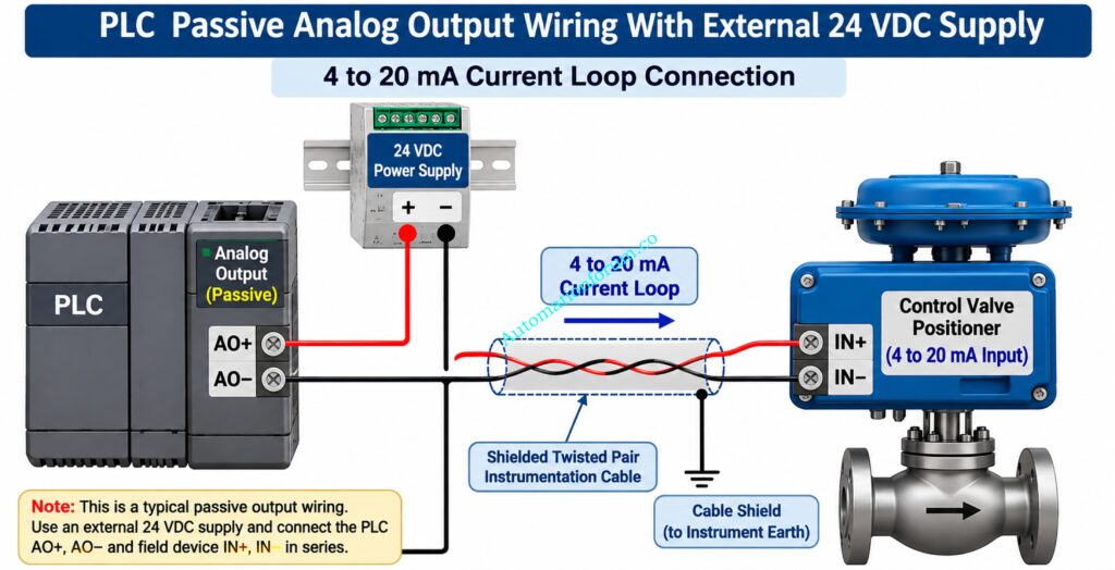
The actual connection must follow the PLC module’s internal circuit diagram. Never connect an external supply to an internally powered output unless the manufacturer permits it.
Step 8: Configure the PLC 4 to 20 mA Output Channel
Configure the selected analog output channel for 4 to 20 mA operation in the PLC hardware configuration software.
Verify the output range and corresponding PLC program scaling.
Eliminate Calibration Errors With Accurate Range Calculation Methods: Transmitter Calibration Span, LRV and URV Value Calculator from Measured 4 to 20 mA
Step 9: Verify PLC Analog Output Wiring Connections
Check terminal tightness, polarity, cable continuity and external supply voltage where applicable.
Step 10: Test the 4 to 20 mA Output Signal
Command different output values from the PLC program and measure the current using a calibrated multimeter connected in series with the current loop.
Verify that the field device responds correctly.
Refer the below link for the Cold and Hot Loop Checking in Automation: Key Differences and Step-by-Step Procedures
PLC 0 to 10 V Analog Output Wiring Procedure
The 0 to 10 V analog output is commonly used for VFD speed references, proportional control devices and other equipment that accepts a voltage reference signal.
Step 1: Identify the PLC Voltage Output Module
Check the module model and confirm that the selected channel supports 0 to 10 V voltage output.
Step 2: Identify the PLC Analog Voltage Output Terminals
Locate the following terminals using the manufacturer’s wiring diagram:
- AO+ for analog voltage output.
- Analog COM for the voltage reference return.
Get Accurate Flow Measurements From Differential Pressure Signals: Differential Pressure Flow Transmitter Output Calculator: 4 to 20 mA
Step 3: Check the Field Device 0 to 10 V Input
Check that the receiving device supports a 0 to 10 V analog input. Verify its input impedance and signal configuration.
Step 4: Select the Shielded Analog Signal Cable
Use suitable shielded twisted pair cable for the analog voltage signal. Route it separately from power cables and VFD motor output cables.
Generate Precise Test Signals Without Connecting Actual Transmitters: How to simulate 4-20ma signal with Loop Calibrator ?
Step 5: Connect the PLC 0 to 10 V Output to the VFD
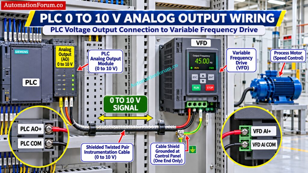
The typical wiring arrangement is:
Connect the PLC voltage output positive to the VFD analog input positive. Connect the PLC analog common to the VFD analog input common.
Step 6: Connect the Analog Cable Shield and Grounding
Terminate the cable shield according to the manufacturer’s instructions and plant grounding philosophy. Avoid connecting signal conductors directly to protective earth.
Calculate Temperature Signals Without Complicated Manual Conversions: How to Calculate Temperature Transmitter 4-20mA Output Using Linear Equation and Percentage Method ?
Step 7: Configure the PLC 0 to 10 V Output Channel
Select voltage output mode and configure the channel for 0 to 10 V operation.
Verify that the PLC program scaling corresponds to the required field device operating range.
Step 8: Configure the VFD Analog Speed Reference Input
For a VFD application, configure the drive analog input for voltage mode. Set the minimum and maximum frequency corresponding to the 0 to 10 V reference.
Step 9: Verify PLC Voltage Output Wiring Connections
Check polarity, terminal tightness, cable continuity and analog common connections.
Step 10: Measure the PLC 0 to 10 V Output Using a Multimeter
Use a calibrated multimeter configured for DC voltage measurement. Connect the meter in parallel across AO+ and analog COM.
Command minimum, intermediate and maximum output values from the PLC and verify the measured voltage.
Stop Guessing Calibration Values and Calculate Every Range Correctly: Transmitter Calibration Calculator: How to Calculate Span, LRV, URV, and 4 to 20 mA
PLC Analog Output Commissioning Procedure and Checklist
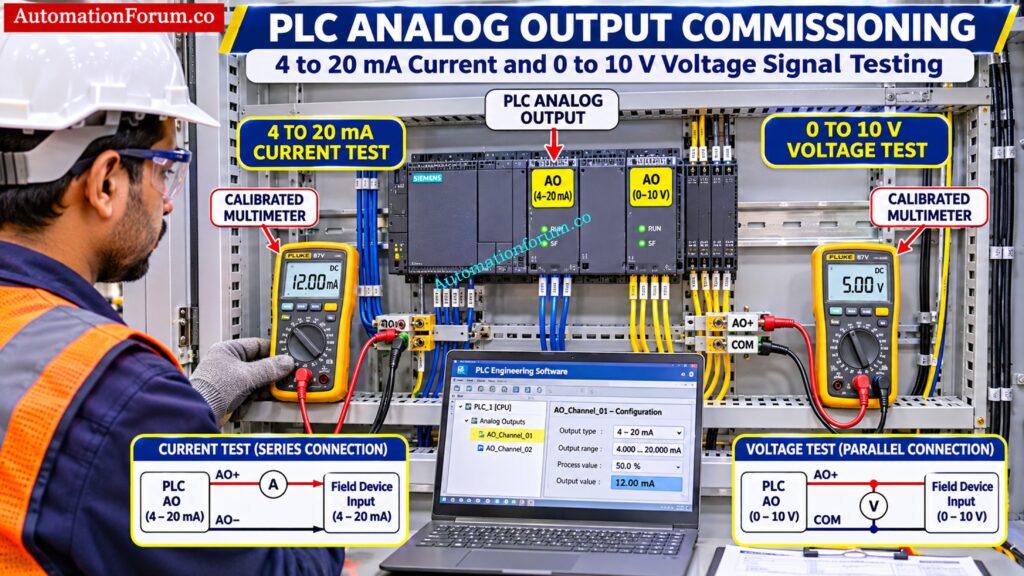
After completing the wiring, perform the following checks before handing over the system for operation.
| No. | Commissioning activity | Verification |
| 1 | Module identification | Confirm module model and channel |
| 2 | Output configuration | Verify current or voltage mode |
| 3 | Wiring inspection | Check terminal tightness |
| 4 | Polarity verification | Confirm positive and return connections |
| 5 | Power supply verification | Check external supply where required |
| 6 | Cable inspection | Verify continuity and shielding |
| 7 | PLC configuration | Confirm output range and scaling |
| 8 | Signal testing | Measure current or voltage |
| 9 | Field device testing | Verify valve or VFD response |
| 10 | Documentation | Record commissioning results |
Important: When measuring 4 to 20 mA, connect the multimeter in series with the current loop. When measuring 0 to 10 V, connect the multimeter in parallel across the output terminals. Never connect a current configured multimeter directly across the output terminals
Avoid Costly Isolation Mistakes in Hazardous Area Instrumentation: Understanding Zener vs Galvanic Isolation in IS Loops for 4 to 20 mA Systems
PLC Analog Output Wiring Problems and Troubleshooting
| Problem | Possible cause | Recommended action |
| Output remains at 4 mA | Minimum command or incorrect scaling | Check PLC output value and scaling |
| Output remains at 0 mA | Open loop or channel fault | Check wiring and module diagnostics |
| Output remains at 0 V | Incorrect configuration or disabled channel | Verify voltage mode and output command |
| Output lower than expected | Excessive loop resistance | Calculate load resistance and check compliance |
| Valve does not respond | Incorrect polarity or input configuration | Check positioner terminals and signal range |
| VFD ignores reference | Incorrect analog input mode | Verify drive parameters and AI terminals |
| Output fluctuates | Electrical interference or grounding issue | Inspect shielding and cable routing |
| Reversed polarity | Incorrect terminal connections | Verify positive and negative connections |
| Module reports channel fault | Overload or wiring problem | Check diagnostics and permitted load |
| Incorrect output range | Current and voltage mismatch | Verify hardware and software settings |
| Output cannot reach 20 mA | Excessive total load | Check receiver impedance and cable resistance |
| Ground loop interference | Different ground potentials | Review isolation and grounding arrangements |
When troubleshooting, measure the signal first at the PLC terminals and then at the receiving device. This helps identify whether the problem originates in the output module, field cable or receiving equipment.
Verify Every Current Loop Before Starting Plant Operations: Live Signal Verification 4 to 20 mA Loop Standard Operating Procedure (SOP)
Important Precautions for PLC Analog Output Wiring
- Always verify the PLC analog output module specifications before connecting field devices.
- Do not interchange current and voltage output connections.
- Confirm whether an external 24 VDC supply is required.
- Check the permitted load resistance for current outputs.
- Verify the receiving device input configuration.
- Maintain proper cable segregation and shielding.
- Do not assume analog common and DC power supply common are interchangeable.
- Complete signal testing before placing the equipment into automatic operation.
Discover Why Current Signals Deliver More Reliable Process Control: Why Engineers Still Trust the 4-20 mA Signal in Automation Systems
Frequently Asked Questions About PLC Analog Output Wiring
How Do You Wire a 4 to 20 mA PLC Analog Output?
Connect the PLC AO+ terminal to the field device IN+ terminal and AO minus to IN minus. Before powering up, check whether the PLC output is internally powered or requires an external 24 VDC supply.
How Do You Wire a 0 to 10 V PLC Analog Output?
Connect the PLC AO+ terminal to the receiving device AI+ terminal and analog COM to AI COM. Make sure both devices are configured for a 0 to 10 V signal.
Avoid Commissioning Failures With These Essential Instrument Checks: Common Instrument Loop Check Problems During Startup
Does a PLC Analog Output Require an External 24 VDC Supply?
Not necessarily, because some PLC modules provide the required power internally. An external 24 VDC supply is needed only when the selected output arrangement requires it.
Can a PLC 4 to 20 mA Output Connect Directly to a VFD?
Yes, you can connect it directly if the VFD supports a 4 to 20 mA analog input. Check the drive parameters and select current input mode before testing the speed reference.
How Do You Test a PLC Analog Output Using a Multimeter?
For a 4 to 20 mA signal, connect the multimeter in series with the current loop. For a 0 to 10 V signal, measure across the output terminals using the DC voltage setting.
Investigate Unexpected Current Readings Before Replacing Your Transmitter: Why Is My Pressure Transmitter Showing 22 mA? Complete Troubleshooting Guide for Instrument Engineers
Why Is 4 to 20 mA Preferred in Process Plants?
Engineers generally prefer 4 to 20 mA because it handles electrical noise better and is less affected by cable resistance. The 4 mA live zero also helps distinguish certain wiring faults from a valid zero process command.
What Happens If PLC Analog Output Polarity Is Reversed?
The receiving device may fail to recognise the signal or may not respond correctly. Check the positive and negative connections against the PLC and field device wiring diagrams.
Why Does a PLC Analog Output Signal Fluctuate?
Fluctuating signals are often caused by electrical interference from VFDs, poor cable shielding, loose terminals or grounding problems. Check the cable routing and grounding connections before replacing the analog output module.
Convert Current Signals Into Accurate Voltage and PLC Counts: Calculator for 4-20mA Signal to 1- 5Volt and PLC 16-bit Raw Count Values
What Is the Purpose of a 250 Ohm Resistor in a 4 to 20 mA Circuit?
A 250 ohm resistor converts the 4 to 20 mA current signal into a corresponding 1 to 5 V voltage signal. It is used in suitable measurement arrangements and is not required for every PLC current output.
Can One PLC Analog Output Channel Provide Both 4 to 20 mA and 0 to 10 V?
Most PLC analog output channels support either current mode or voltage mode at a time. Check the module datasheet because the available output combinations depend on the manufacturer and model.
Find the Real Cause Behind Loop Reading Differences: Loop Checking Field vs Control Room Reading Mismatch Explained
Final Recommendations for PLC 4 to 20 mA and 0 to 10 V Wiring
Correct PLC analog output wiring requires proper identification of the output terminals, selection of the correct signal type, verification of current loop power requirements and accurate connection to the receiving field device.
Following the above procedures for 4 to 20 mA and 0 to 10 V signals helps ensure reliable communication between PLC systems and field equipment during installation, commissioning and plant operation.
Always follow the specific PLC module and field device manufacturer’s wiring diagrams before applying power.
Refer the below link for the Understanding the Difference Between Live Zero and Dead Zero in 4 to 20 mA
