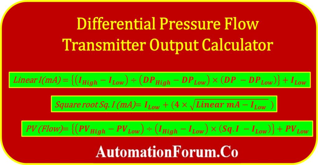
- Formulas in this calculator
- Formula for linear mA calculation
- Formula for Square root mA calculation
- Formula for flow rate calculation
- Significance of Differential pressure Flow Transmitter Output Calculator
- Example calculation
- Linear mA calculation
- Square root mA calculation
- Flow rate calculation
- Differential pressure transmitter flow rate output calculator
The flow is calculated in a way that is directly proportional to the differential pressure (DP). Therefore, in order to calculate the flow value, the linear variable that was measured by the transmitter needs to have its value converted into a square root.
Formulas in this calculator
The following equations serve as the basis for this calculator’s operation.
Formula for linear mA calculation
Below is the formula for determining the linear mA current output from the differential pressure of the transmitter with indicated differential pressure.

Formula for Square root mA calculation
A linear mA current signal can be converted into a square root output mA current signal by applying the following formula.

Formula for flow rate calculation
The formula that follows determines the flow rates of the process based on the estimated square root of the mA current signal.

Where:
I High = Maximum mA output signal from the transmitter
I low = Minimum mA output signal from the transmitter
I mA = Actual linear mA current output
Sq.I (mA) = Square root mA output signal
DP High = Differential pressure high (URV) value of the transmitter
DP Low = Differential pressure low(LRV) of the transmitter
DP = Actual differential pressure(DP) indicated by the transmitter
PV high = Maximum flow rate – Upper range value scaled in the control system
PV Low = Minimum flow rate – lower range value scaled in the control system
PV Flow = Actual flow rate value shown in the control system
Significance of Differential pressure Flow Transmitter Output Calculator
Accuracy Verification:
- A DP flow transmitter is a critical component in flow measurement systems, and its output signal should accurately reflect the actual flow rate.
- The calculator allows technicians to compare the expected output with the measured output, enabling them to verify the accuracy of the transmitter.
- This verification process ensures that the flow measurement system is providing reliable and precise data.
Troubleshooting Assistance:
- When flow measurement discrepancies occur, the calculator serves as a valuable troubleshooting tool.
- By analyzing the expected output signal based on the measured differential pressure, technicians can identify potential issues within the system.
- It helps pinpoint whether the problem lies with the transmitter
Calibration Guidance:
- Regular calibration of DP flow transmitters is necessary to maintain accurate measurements.
- The calculator assists technicians in calibrating the transmitter by providing reference output signals for specific differential pressure ranges.
- It helps ensure that the transmitter is adjusted correctly to match the desired flow rates, enhancing the overall measurement accuracy.
Time and Cost Savings:
- The calculator streamlines maintenance and commissioning activities by providing quick and accurate calculations of the expected output signal.
- This reduces the time spent on manual calculations and minimizes errors.
- By efficiently identifying and addressing any issues, technicians can prevent costly downtime and ensure the system operates optimally.
Example calculation
You can better understand the conversion process by using the calculation in the example below.
The differential pressure transmitter has a range of 0 to 500 mBar, and it is currently showing 250 mBar. In addition, the range of the scaled flow is from 0 to 200 m3/hr. What is the expected value for the current flow rate?
I High = 20mA
I low = 4mA
DP High = 500 mBar
DP Low = 0mBar
DP = 250 mBar
PV high = 200 m3/hr
PV Low = 0 m3/hr
I mA = ?
Sq.I (mA) = ?
PV Flow = ?
Linear mA calculation
Linear I(mA) = {(IHigh – ILow) ÷ (DPHigh – DPLow) × (DP – DPLow)} + ILow
= {(20-4)÷(500-0)×(250-0)}+4
= {(16÷500)×250}+4
Linear I(mA) = 12.000 mA
Square root mA calculation
Square root Sq. I (mA) = ILow + {4 x ?(Linear mA – ILow )}
= 4+4?12-4
= 4+4?8
Square root Sq. I (mA) = 15.314 mA
Flow rate calculation
PV (Flow) = {(PVHigh – PVLow ) ÷ (IHigh – ILow) × (Sq.I – ILow)} + PVLow
= {(200-0)÷(20-4)×(15.314-4)}+0
= 200÷16×11.314
PV (Flow rate) = 141.425 m3/hr
Differential pressure transmitter flow rate output calculator
Use the following calculator to determine the flow rate, as well as the linear and square root output mA signals, based on the differential pressure that is being displayed by the differential pressure flow transmitter.
Click here for more Instrumentation Calculators