- Why Resolution in PLCs Matters in Industrial Automation
- What Is Resolution in PLCs? (Core Concept Explained)
- How to Calculate Resolution in PLCs
- Resolution vs Accuracy vs Precision in PLC Systems
- PLC Resolution Calculation Examples (Step-by-Step)
- Signed vs Unsigned Integer Resolution in PLCs
- Analog Resolution in PLCs and ADC Considerations
- PLC Resolution vs Sensor Resolution
- Resolution vs PLC Scan Time and Sampling Rate
- Mapping Raw PLC Counts to Engineering Units
- Example mapping: 4-20 mA input scaled to 0-100 units using 16-bit unsigned
- Analog Output (AO) Resolution in PLCs
- Common PLC Resolution Mistakes and How to Avoid Them
- Impact of PLC Resolution on PID Control Performance
- How Many Bits Do You Need in a PLC? (Resolution Selection Guide)
- Practical Limits to PLC Resolution in Real Industrial Plants
- PLC Resolution Commissioning Checklist
- Real-World PLC Resolution Examples and Calculations
- Resolution Differences Across PLC Manufacturers
- Final checklist for Engineering Handover
- Role of Resolution in Alarms and Trip Systems
- PLC Resolution vs HMI Display Resolution
- Frequently Asked Questions (FAQ) on Resolution in PLCs
Why Resolution in PLCs Matters in Industrial Automation
If you design, commission, or maintain control systems, understanding resolution in PLCs is non-negotiable. Resolution is the smallest change a PLC can detect or represent. It determines how precisely you can measure temperature, pressure, speed, position, or any analog signal. For instrumentation and calibration engineers (like many readers here), resolution affects scaling, alarm accuracy, PID tuning, and traceability of calibration certificates.
This guide is written for automation engineers, instrumentation technicians, and controls specialists. It’s SEO-optimized for queries like PLC resolution, 16-bit unsigned vs signed, analog input resolution, and how to calculate PLC step size. You’ll get clear formulas, worked examples (digit-by-digit), practical tips, and common mistakes to avoid.
What Is Resolution in PLCs? (Core Concept Explained)
Definition of Resolution in PLC Systems
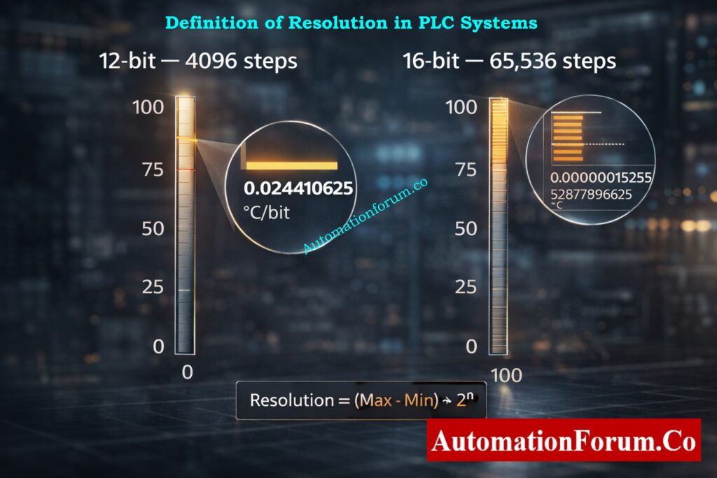
Resolution = smallest increment the PLC can represent.
It depends entirely on the number of discrete steps a value can take – which in turn depends on the number of bits used to store that value.
Instant Coriolis Mass Flow Calculator: Coriolis Mass Flow Calculator – Complete Guide for Instrumentation & Process Engineers
How to Calculate Resolution in PLCs
Key formula:
Resolution (step size) = (Max Value − Min Value) ÷ Number of steps
And:
Number of steps = 2ⁿ where n = number of bits.
Resolution vs Accuracy vs Precision in PLC Systems
Resolution, accuracy, and precision are often confused in PLC and instrumentation systems, but they are not the same.
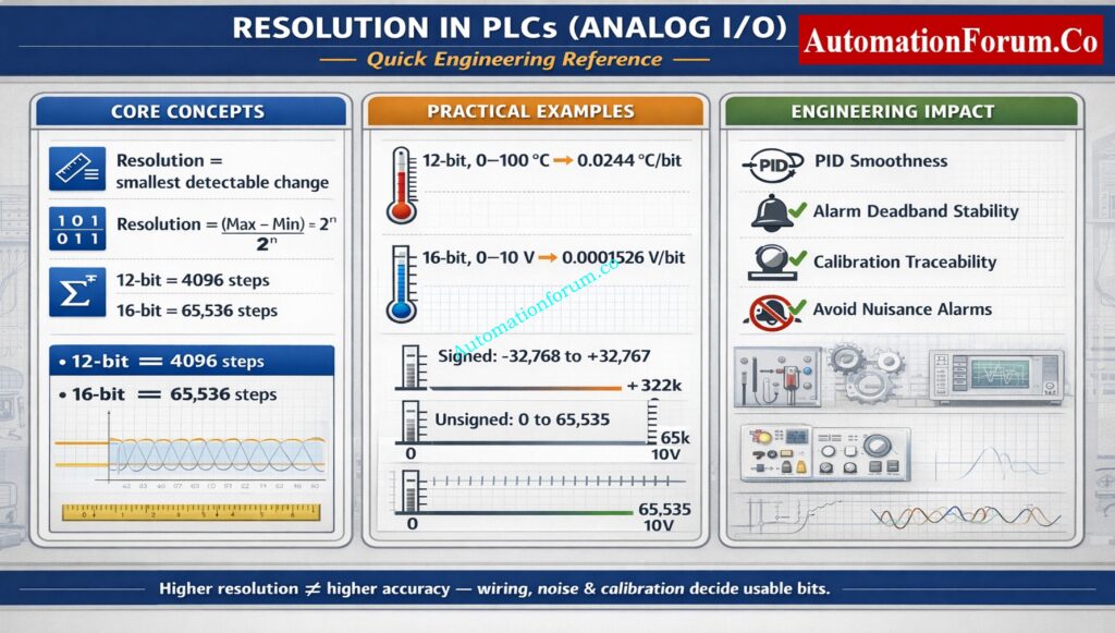
Resolution defines the smallest detectable change in a signal based on bit depth. Accuracy indicates how close the measured value is to the true value. Precision refers to repeatability of measurements.
A PLC can have high resolution but poor accuracy if the sensor or calibration is incorrect. Likewise, high accuracy with low resolution results in coarse signal steps. For reliable control, all three must be considered together.
PLC Resolution Calculation Examples (Step-by-Step)
12-Bit Resolution Example (0–100 °C Sensor)
A common sample: a 12-bit sensor that measures 0 °C to 100 °C.
- Number of steps = 2¹² = 4096.
- Resolution = (100 − 0) ÷ 4096.
Let’s compute that carefully:
- 4096 × 0.0244140625 = 100.0000000 (so resolution is exact to many decimals)
- Therefore resolution = 0.0244140625 °C per bit
(rounded commonly to 0.02441 °C/bit)
This means the PLC/ADC cannot distinguish temperature changes smaller than ~0.02441 °C.
16-Bit Unsigned Resolution Example (0–10 V Analog Input)
A common PLC input is 0–10 V mapped to a 16-bit unsigned integer.
- Number of steps = 2¹⁶ = 65,536.
- Resolution = (10 V − 0 V) ÷ 65,536.
Compute:
- 10 ÷ 65,536 = 0.000152587890625 V per bit
(Rounded: 0.00015259 V/bit)
So each increment in the ADC raw value represents ~152.6 μV.
16-Bit Signed Resolution for Bipolar Signals
If a signed 16-bit integer is used for a bipolar signal (for example −5 V to +5 V mapped to signed counts), the effective symmetric step count per side is 2¹⁵ = 32,768.
If you map −5 V to +5 V on a signed 16-bit:
- Steps per side = 32,768
- Resolution = (5 V − (−5 V)) ÷ 65,536 = 10 ÷ 65,536 = same as unsigned example above.
However, when you reason per side, you often think in ±5 V mapped to −32,768 … +32,767 counts, which halves the positive/negative bucket for sign encoding reasons.
Refer the below link for the PLC Raw Count Calculator: Comparison with PLC Internal Scaling Blocks, Real-World Use Cases and Practical Benefits
Signed vs Unsigned Integer Resolution in PLCs
16-Bit Unsigned Integer Resolution
- Range: 0 to 65,535 (total 65,536 steps)
- Use: raw ADC counts, timers, counters, encoders when only positive values exist
- Behavior: full positive range, no sign bit, best full-scale usage for non-negative signals
16-Bit Signed Integer Resolution
- Range: −32,768 to +32,767 (total 65,536 steps, but split)
- Use: signals that can go positive or negative like velocity, bidirectional position, temperature offset around 0
- Behavior: effectively half the steps available for positive values and half for negative values
PLC Data Types Engineers Must Know: PLC Data Types Every Automation Engineer Must Know to Avoid Costly Programming Errors
When to Use Signed or Unsigned Data Types
Practical point: If your signal is inherently always positive (0–100), using signed integers wastes half the useful counts. For best resolution use unsigned for strictly positive ranges and signed for bipolar signals.
Analog Resolution in PLCs and ADC Considerations
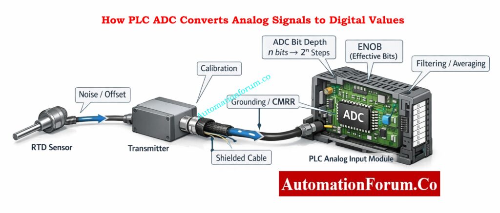
How PLC ADC Converts Analog Signals to Digital Values
Impact of PLC Resolution on PID Control Performance
When you connect a physical sensor (RTD, thermocouple with transmitter, 4–20 mA loop, or 0–10 V) the ADC inside the PLC converts that voltage/current into discrete digital counts.
Factors Affecting ADC Resolution Beyond Bit Depth
- ADC architecture (SAR, delta-sigma, successive approximation)
- Input range and any front-end scaling (resistors, op-amps)
- Input noise and signal-to-noise ratio (SNR)
- Filtering and averaging (digital or analog)
- Grounding and common-mode rejection
- Calibration offsets and gain errors
- Nonlinearity and hysteresis of sensors
Effective Number of Bits (ENOB) in PLC Analog Inputs
Even a 16-bit ADC can be effectively fewer bits of usable resolution if noise or poor wiring degrade the SNR. In practice, 16-bit resolution often delivers 12–14 bits of effective bits (ENOB) in noisy industrial environments unless you manage wiring and filtering carefully.
Why 4–20 mA Still Dominates: Why Engineers Still Trust the 4-20 mA Signal in Automation Systems
PLC Resolution vs Sensor Resolution
PLC resolution and sensor resolution are independent parameters. The overall system resolution is always limited by the weakest element.
If a sensor provides only 0.5 °C resolution, using a 16-bit PLC analog input will not improve measurement accuracy. Conversely, a high-resolution sensor connected to a low-resolution PLC input wastes sensor capability.
Effective system resolution = minimum(sensor resolution, ADC resolution, signal noise limit).
82 Must-Have Instrumentation Documents: 82 Essential Drawings and Documents for Instrumentation and Control Engineers
Resolution vs PLC Scan Time and Sampling Rate
Resolution tells you how little a change in a signal can be seen, and scan time tells you how often the PLC reads that change.
A PLC with high resolution and slow scan time might not pick up signals that change quickly. Also, if the scan duration is fast but the resolution is low, the measurements will be wrong.
When dealing with dynamic processes, you need to choose both the resolution and the sample rate at the same time to make sure the control is stable.
DP to Flow Calculator Explained: Differential Pressure to Flow Calculator – Complete Interactive Tool for Process Engineers
Mapping Raw PLC Counts to Engineering Units
Always write down and check the scaling formula in calibration certificates and project documents.
Standard Scaling Formula Used in PLCs
EngineeringValue = ((RawCount − RawMin) ÷ (RawMax − RawMin)) × (EU_Max − EU_Min) + EU_Min
Where:
- RawMin/RawMax = ADC counts corresponding to EU_Min/EU_Max
- EU_Min/EU_Max = engineering units range (e.g., 0–100 °C or 4–20 mA → 0–100%)
Best Practices for PLC Signal Scaling
- Store RawMin and RawMax constants in one location (like a calibration block) so that they can be checked.
- For intermediate scaling, use floating-point, but round to show precision only.
- Document the final display precision and alarm deadbands with reference to step size.
- For safety circuits, avoid relying on rounding to hide quantization — use deterministic thresholds.
Master Instrument and Electrical Drawings: Complete Guide to Interpreting Instrument and Electrical Drawings for Engineers
Example mapping: 4-20 mA input scaled to 0-100 units using 16-bit unsigned
Assume the input is digitized such that:
- RawMin (4 mA) = 0 counts
- RawMax (20 mA) = 65,535 counts
Map raw count 32,768 → engineering value?
Step-by-step:
- Fraction = (32,768 − 0) ÷ 65,535 = 32,768 ÷ 65,535.
- 32,768 × 2 = 65,536; 65,536 is 1 greater than 65,535, so the fraction is almost 0.5 but slightly less.
- Numerically: 32,768 ÷ 65,535 ≈ 0.5000076295? (We’ll compute: it’s ≈0.5000076295? Actually exact value: 32,768 / 65,535 ≈ 0.5000076295109483)
- EngineeringValue = Fraction × (100 − 0) + 0 = Fraction × 100 ≈ 50.00076295 units.
So raw count 32,768 maps to ~50.0008 units, slightly over exact half due to asymmetric denominator (65535).
Lesson: When mapping counts, consider whether your ADC uses 0…65535 or 0…65536 semantics; always verify vendor docs.
Convert Engineering Units to PLC Counts: Engineering Units to PLC Raw Counts Conversion Calculator
Analog Output (AO) Resolution in PLCs
Analog output resolution determines the smallest change a PLC can apply to actuators such as control valves or variable speed drives.
For a 16-bit analog output with a 0–10 V range, each step represents approximately 0.00015 V. Low AO resolution causes stepwise output changes, leading to valve hunting or unstable speed control.
High-resolution analog outputs are critical for precise flow, pressure, and speed control applications.
4–20 mA to PLC Counts: Calculator for 4-20mA Signal to 1- 5Volt and PLC 16-bit Raw Count Values
Common PLC Resolution Mistakes and How to Avoid Them
- Using signed vs unsigned incorrectly.
If your signal is always positive, using signed storage loses half the dynamic range. - Not accounting for ADC offset or calibration error.
Always calibrate end-points and include offset/gain compensation. - Rounding too early.
Round only for display. Keep full precision internally until final output. - Expecting theoretical resolution equals usable resolution.
Noise, grounding, and ADC ENOB reduce usable bits. Improve wiring and filtering to raise effective bits. - Scaling mistakes causing alarm thrashing.
If alarm deadbands are smaller than step size, alarms may oscillate. Set alarms with hysteresis at least ± one or two counts. - Treating counts as engineering units in documentation.
Always show both raw counts and engineering units in calibration and handover docs.
Hands-On PID Tuning Simulator: Best PID Controller Tuning Simulation Tool for Engineers
Impact of PLC Resolution on PID Control Performance
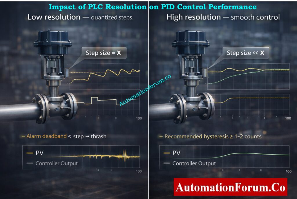
PLC resolution has a direct impact on PID loop stability and performance. Low resolution causes quantization errors, resulting in step changes instead of smooth control output.
Poor resolution can lead to limit cycling, oscillations, and excessive valve movement. High-resolution inputs and outputs allow finer PID adjustments, smoother control action, and reduced mechanical wear.
For tight control loops, resolution should be significantly smaller than the smallest process change requiring correction.
Excel-Based PID Loop Simulator: Excel based PID Loop Simulator
How Many Bits Do You Need in a PLC? (Resolution Selection Guide)
- 8–12 bits: low-cost PLCs, coarse signals, noncritical status. Use only for non-precision loops.
- 12–14 bits: decent for general analog measurements, simple PID loops.
- 16 bits: recommended for precise instrumentation (flow, mass, high-accuracy temperature) if wiring and SNR are good.
- Higher than 16 bits: specialized DAQ or controllers for lab or high-precision metrology.
Rule of thumb: Choose bit depth so that step size is at least an order of magnitude (10×) smaller than the smallest change you care to detect.
Example: If you need ±0.1 °C resolution over 0–100 °C, step size ≤ 0.1. With 12 bits step = 0.0244 °C – OK. With 8 bits step = 0.39 °C – not OK.
Practical PID Controller Tuning: PID controller tuning
Practical Limits to PLC Resolution in Real Industrial Plants
In real industrial environments, usable PLC resolution is often lower than theoretical resolution.
Electrical noise, poor grounding, long cable runs, EMI, temperature drift, and improper shielding reduce effective number of bits (ENOB). As a result, a 16-bit input may behave like a 12-bit system in harsh conditions.
Good wiring practices, proper grounding, shielding, and signal filtering are essential to achieve usable resolution.
PLC Permissive Logic Troubleshooting Guide: PLC Permissive Logic Troubleshooting Procedure for Instrumentation Engineers
PLC Resolution Commissioning Checklist
- Verify ADC bit depth and signed/unsigned mode in PLC docs.
- Confirm input ranges and any front-end scaling (is 0–10 V truly mapped to 0…65535?).
- Measure noise floor — compute ENOB if possible.
- Calibrate two-point (span and zero) and log raw counts before/after.
- Set alarm deadbands/hysteresis > step size.
- Document mapping formulas and store in version control.
Dead Zero Problem Explained Clearly: Beyond Zero: Understanding the Dead Zero Problem in Industrial Analog Signals
Real-World PLC Resolution Examples and Calculations
12-bit sensor, 0–100 °C:
- Steps = 2¹² = 4096.
- Resolution = 100 ÷ 4096 = 0.0244140625 °C/bit.
16-bit unsigned, 0–10 V:
- Steps = 2¹⁶ = 65,536.
- Resolution = 10 ÷ 65,536 = 0.000152587890625 V/bit ≈ 152.6 μV/bit.
Signed 16-bit for ±range:
- Steps per side = 2¹⁵ = 32,768. If mapping −10 V…+10 V to signed counts, resolution = 20 ÷ 65,536 = same as unsigned full span — but positive/negative split matters for indexing and alarms.
Turbine Flow Meter Scaling Calculator: Turbine Flow Meter Coefficient and Scaling Factor Calculator
Resolution Differences Across PLC Manufacturers
PLC resolution varies by manufacturer and analog module design.
Many Siemens PLC analog inputs scale 0–10 V to 0–27,648 counts, while Allen-Bradley modules often use the full 16-bit range. Schneider and Yokogawa modules may use different internal scaling and filtering methods.
Always refer to vendor manuals to confirm raw value ranges before scaling and calibration.
Scale Analog Signals in PLCs: Scaling Analog Values in Industrial Automation (PLC)
Final checklist for Engineering Handover
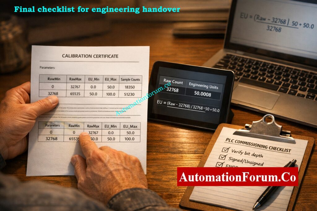
- Include raw counts + mapped engineering units in punch list.
- State ADC bit depth and signed/unsigned setting.
- Provide calibration certificate with end-point counts and dates.
- Specify alarm deadband relative to step size.
- Note ENOB or measured noise floor if available.
Resolution is the bridge between the physical world and your PLC’s digital brain.
Choose the right bit depth, use the correct signed/unsigned representation, document scaling precisely, and always validate usable resolution in the field (not just on paper). If you do those four things, your control loops will be more accurate, alarms more stable, and calibration records more defensible.
Increase PLC Speed Without Hardware: How to Increase PLC Speed: 7 Optimization Tips + Advanced Programming Guide
Role of Resolution in Alarms and Trip Systems
Resolution plays a critical role in alarm and trip system design. Alarm setpoints must account for resolution step size to avoid nuisance alarms or missed trips.
If alarm thresholds are closer than one resolution step, the PLC may not detect the condition reliably. Proper alarm deadbands and safety margins must always consider PLC resolution.
This is especially important for safety instrumented systems and shutdown logic.
Essential PLC System Documentation Guide: PLC System Documentation Guide: Essential Records for Industrial Automation Success
PLC Resolution vs HMI Display Resolution
PLC resolution and HMI display resolution are not the same.
An HMI may display values with many decimal places, but the actual PLC resolution limits the true measurement. Displaying extra decimals does not increase accuracy or resolution.
Engineering decisions should always be based on PLC resolution, not visual display precision.
Key Rule: PLC resolution determines what the controller can detect, accuracy determines correctness, and display decimals only affect appearance not control quality.
Hot Standby PLC Systems Explained: Hot Standby in PLC Systems: Architecture, Working, and Benefits
Frequently Asked Questions (FAQ) on Resolution in PLCs
What is resolution in a PLC?
Resolution in a PLC is the smallest change in an input or output signal that the PLC can detect or represent. It depends on the number of bits used to store the value and the signal range.
How do you calculate PLC resolution?
PLC resolution is calculated using the formula:
Resolution = (Maximum Value − Minimum Value) ÷ 2ⁿ,
where n is the number of bits used by the PLC or ADC.
What is the resolution of a 16-bit PLC?
A 16-bit PLC has 65,536 discrete steps (2¹⁶). The actual resolution depends on the signal range—for example, a 0–10 V signal has a resolution of approximately 0.00015 V per bit.
What is the difference between signed and unsigned resolution in PLCs?
Unsigned integers use the full range for positive values (0 to 65,535), giving better resolution for unipolar signals. Signed integers split the range into positive and negative values, reducing usable resolution per side.
Why is PLC resolution important in analog signals?
PLC resolution determines how accurately analog signals like temperature, pressure, or flow can be measured. Higher resolution allows detection of smaller signal changes, improving control accuracy and stability.
What happens if PLC resolution is too low?
Low resolution causes large step sizes, leading to poor measurement precision, unstable PID control, inaccurate alarms, and scaling errors in analog signals.
Which PLC data type gives better resolution?
For positive-only signals, unsigned integers give better resolution because they use the full numeric range. Signed integers are better for signals that can go positive and negative.
What is the resolution of PLC analog?
The smallest change in an analog signal that the PLC can see is called PLC analog resolution. It depends on the ADC’s bit depth and signal range, which is (Max − Min) ÷ 2ⁿ.
What is 16-bit resolution?
The signal is split into 65,536 separate steps (2¹⁶) when it has a 16-bit resolution. This makes it possible to find very minor changes in analog signals, which makes measurements more accurate.
What is resolution in a control system?
In a control system, resolution is the smallest change in a variable that the system can measure or control. Higher resolution makes it easier to control things and gives you more accurate feedback.
What does 12-bit resolution mean?
The 12-bit resolution breaks the signal range down into 4,096 steps (2¹²). Each step is a set amount that tells you how precise the signal may be measured or regulated.
What is a 24-bit resolution?
With 24-bit resolution, you can measure very minor changes in signals with 16,777,216 steps (2²⁴). It is often employed in systems for collecting data and high-precision instruments.
Which is better, 10-bit or 12-bit?
12-bit resolution is superior since it has four times as many steps as 10-bit resolution. This makes the step size lower, the accuracy higher, and the control accuracy better.
What is the difference between 12-bit and 14-bit resolution?
With 12 bits of resolution, there are 4,096 steps. With 14 bits of resolution, there are 16,384 steps. The 14-bit system offers four times finer resolution and more precise signal measurement.
What is resolution in process control?
Resolution in process control refers to the smallest change in a process variable that the control system can detect or adjust. Higher resolution improves stability, accuracy, and control performance.
Refer the below link to Optimize PLC Scan Time Fast