- Why the 4-20 mA Signal Continues to Dominate Modern Plants
- Understanding the 4 to 20 mA Signal
- Live Zero Advantage in the 4 to 20 mA Signal
- Noise Immunity of the 4 to 20 mA Current Loop
- Long Distance Transmission Capability of 4 to 20 mA Signals
- Loop Powered Transmitter Principle
- Open Circuit and Fault Detection in 4 to 20 mA Loops
- Ground Loop Risks in 4 to 20 mA Systems
- Correct Shielding Practices for 4 to 20 mA Cables
- Importance of Proper Scaling in 4 to 20 mA Signals
- Effect of Cable Resistance on 4 to 20 mA Signals
- Industry Standard Signal
- Why 4 to 20 mA Remains the Industry Standard Signal
- Key Lessons for Technicians
- FAQ On 4 to 20 mA signal
Why the 4-20 mA Signal Continues to Dominate Modern Plants

Technologies change quickly in the field of industrial automation. Every year, new communication protocols, smart instruments, and digital control platforms come forth. Even with all of these improvements, one signal has lasted the test of time and is still the most important in the field. The 4 to 20 mA signal is still the most dependable way to measure and control things in many businesses throughout the world.
The 4 to 20 mA current loop is still the most reliable way to send process data, whether it’s from oil and gas refineries, chemical plants, water treatment plants, or power production units. Engineers and technicians still use this basic but effective signal, even in modern factories with smart gadgets and digital networks.
It’s not because of past. The reason is performance, dependability, and usefulness in real-world industrial settings. This article talks about why the 4 to 20 mA signal won’t go away and lists 10 important elements that every technician should know in order to work with this industry standard safely and confidently.
Understanding the 4 to 20 mA Signal
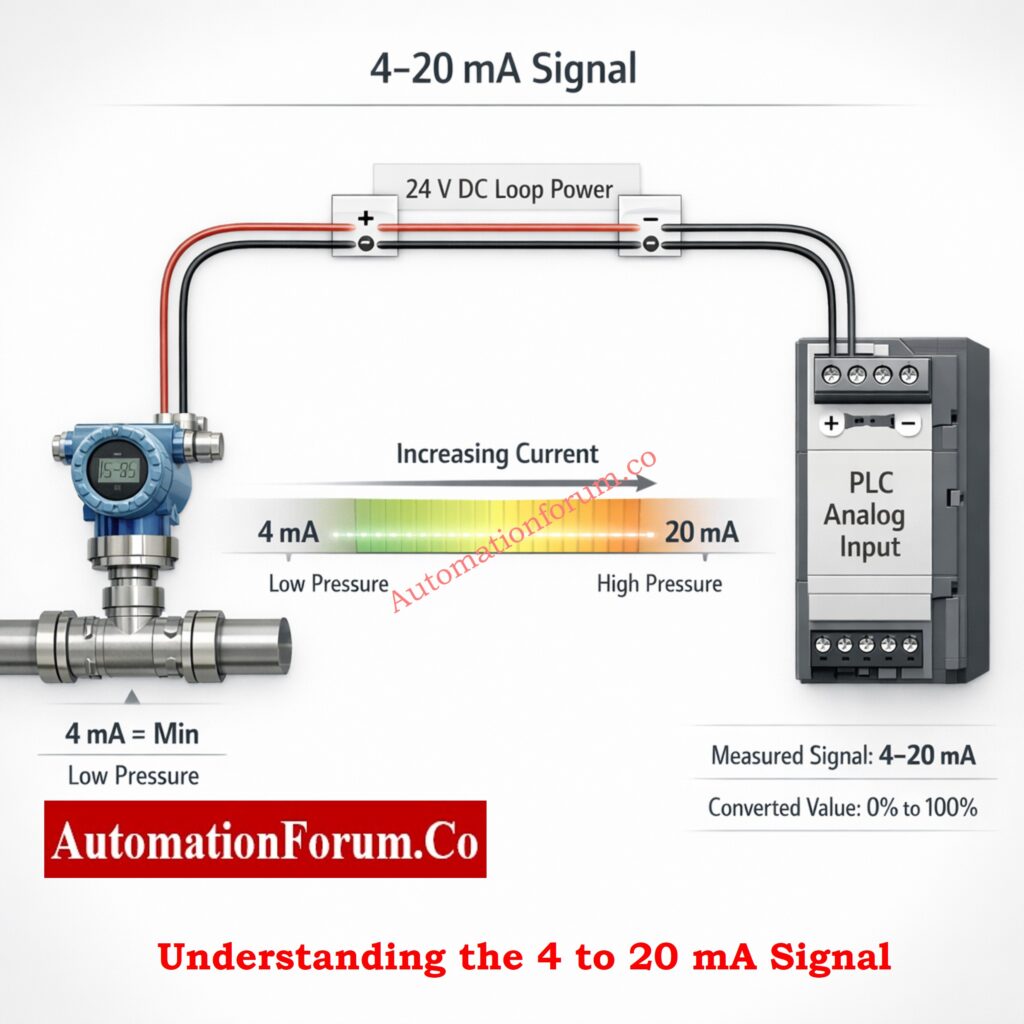
- The 4 to 20 mA signal is an analog current signal that shows a physical process variable like pressure, temperature, flow, or level.
- A field transmitter takes a process value and turns it into a current that is proportionate to that value, between 4 mA and 20 mA.
- In this system, 4 mA is the lowest process value and 20 mA is the highest process value.
- There is a linear relationship between the measured variable and any value between these two boundaries. In a pressure transmitter that goes from 0 to 10 bars, 4 mA means 0 bars and 20 mA means 10 bars.
- The signal is based on current, not voltage, which makes it much more accurate, immune to noise, and able to be sent over long distances.
- These traits are what have made it so successful in industrial automation for so long.
Why Twisted Pair Cables Are Critical for Reliable 4–20 mA & RS-485 Signals: Twisted Pair Cable in Industrial Signal Transmission: The Essential Guide for 4-20 mA and RS 485 Systems
Live Zero Advantage in the 4 to 20 mA Signal
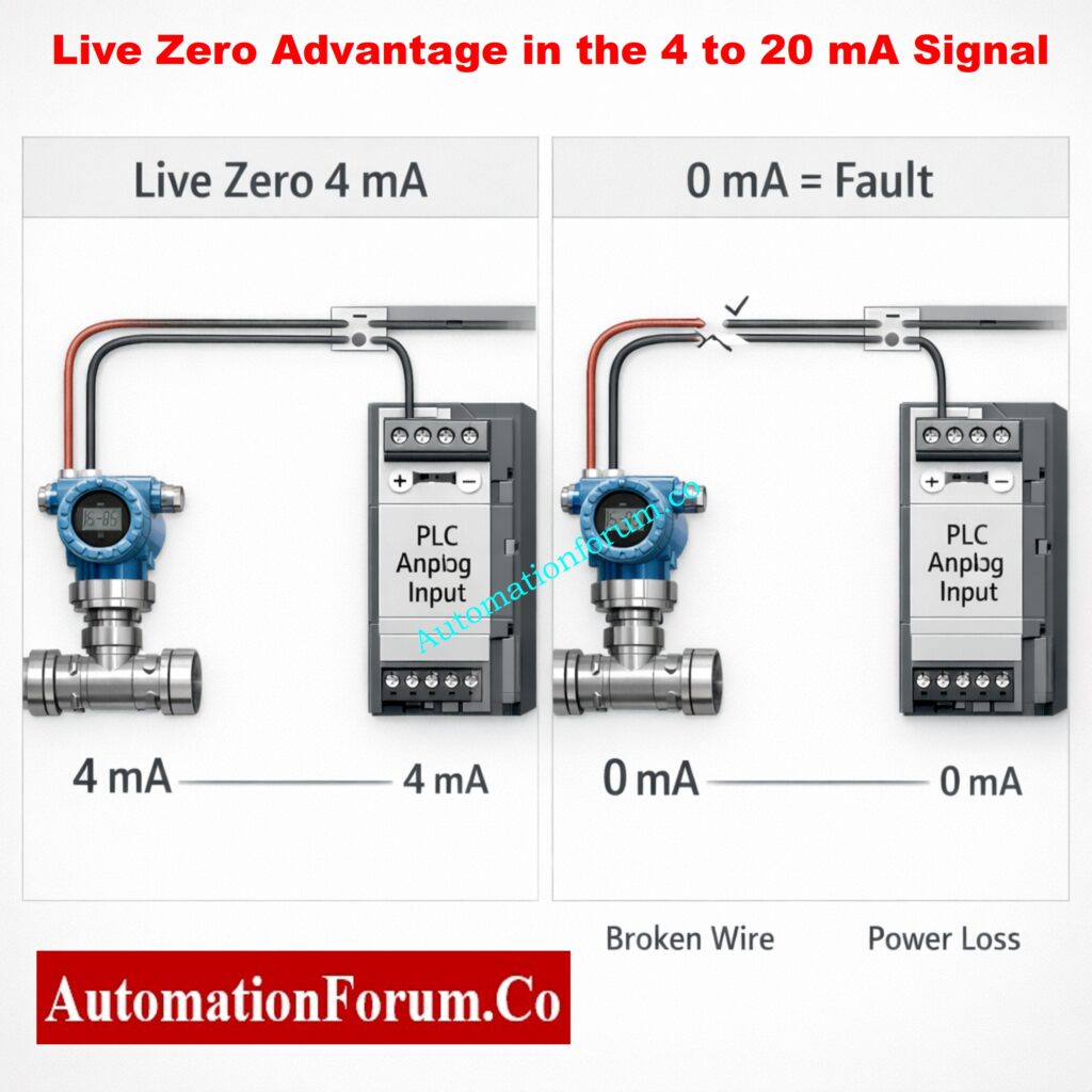
- The idea of “live zero” is one of the most significant parts of the 4 to 20 mA signal.
- In the 4 to 20 mA system, 4 mA stands for zero process value, but in voltage signals, zero volts frequently means zero measurement.
- This design makes it easy to tell the difference between a valid measurement and a fault state.
How Live Zero Improves Fault Detection
- Even when a transmitter is working properly and measuring zero process value, it nevertheless sends out 4 mA. If the signal abruptly drops to 0 mA, it means there is a problem right away.
- Technicians should know the following important things about live zero.
- Even if the process value is at its lowest point, a 4 mA signal shows that the transmitter is energized and working properly.
- A 0 mA signal usually means there is a problem with the wiring, the transmitter electronics, the cable, or the power supply.
- This feature makes it easier to find and fix problems quickly and lowers the chance of mistaking a fault for a normal process condition.
- In important situations, the 4 to 20 mA signal is far better than many voltage-based alternatives since it has live zero.
Refer the below link for the Step-by-Step 4–20 mA Loop Troubleshooting Using a Loop Calibrator
Noise Immunity of the 4 to 20 mA Current Loop

- Electricity is really bad for industrial enterprises. Electromagnetic interference from big motors, variable frequency drives, contactors, transformers, welding machines, and high-voltage cables may quickly mess up delicate communications.
- Voltage signals are especially weak since any voltage that is added directly changes the recorded value.
- Even a little bit of noise can make readings unreliable and cause problems with control.
- The 4 to 20 mA signal, on the other hand, works with current. The current stays stable as long as the loop stays intact, even if noise causes voltage to build up in the cable.
Why Current Signals Perform Better Than Voltage Signals
- Some important parts of noise immunity are as follows.
- Even when there is electromagnetic interference along the cable route, the current stays the same.
- Even when signal wires are close to power cables or heavy electrical equipment, measurements stay the same.
- Control systems get accurate data, which cuts down on false alarms and the need for operators to step in.
- The 4 to 20 mA signal is preferred in industrial automation because it is naturally resistant to noise.
Why Engineers Prefer 4–20 mA Over Voltage Signals in Instrumentation: Why 4-20 mA Current Signal is Preferred Over Voltage Signal in Instrumentation?
Long Distance Transmission Capability of 4 to 20 mA Signals

- In a lot of factories, field instruments are set up far away from the control room or PLC panel.
- Storage tanks, pipelines, cooling towers, and remote pump stations often need to send signals over hundreds or even thousands of meters.
- As the length of a wire increases, voltage signals lose voltage. This leads to readings that are not correct and measurements that are not dependable.
- This is not a problem for the 4 to 20 mA signal.
- The following are some of the main benefits of long-distance transmission.
- The value stays the same no matter how long the cable is, as long as the loop has enough supply voltage.
Why 4 to 20 mA Is Ideal for Remote Instruments
- Even over very long cable lines, the accuracy of the measurements stays the same.
- You can connect remote instruments without having to do complicated signal processing.
- This feature makes the 4 to 20 mA signal perfect for big plants and installations that are spread out over a vast area.
Instant 4–20 mA Transmitter Output Calculator for Process Values: 4 to 20 mA Transmitter Output Process Value Calculator
Loop Powered Transmitter Principle
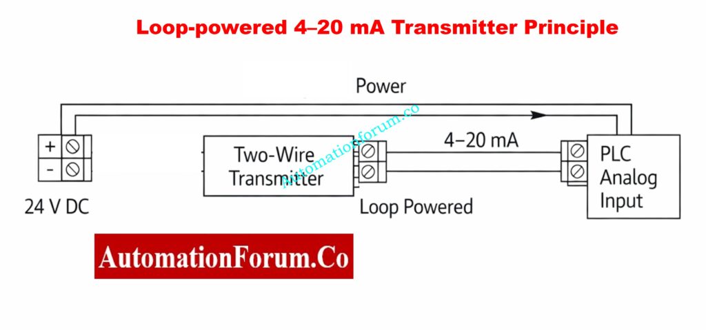
- The loop-powered transmitter idea is one of the best things about the 4 to 20 mA system. The transmitter gets its power and the measurement signal travels over the same two wires in this configuration.
- The loop provides power to the transmitter, which then adjusts the loop current based on the detected process value.
- Technicians should know the following benefits of loop-powered systems.
Benefits of Loop Powered Transmitters
- The wiring is easier because the transmitter doesn’t need a separate power supply cable.
- Costs of installation go down, and the system is less complicated.
- Safety is better, especially in dangerous places where lower power levels are better.
- It can work safely in explosive situations since it works with intrinsic safety barriers and isolators.
- The 4 to 20 mA signal is so popular in many fields, in part because of its attractive appearance.
Refer the below link for Understanding the Difference Between Live Zero and Dead Zero in 4 to 20 mA Signals
Open Circuit and Fault Detection in 4 to 20 mA Loops
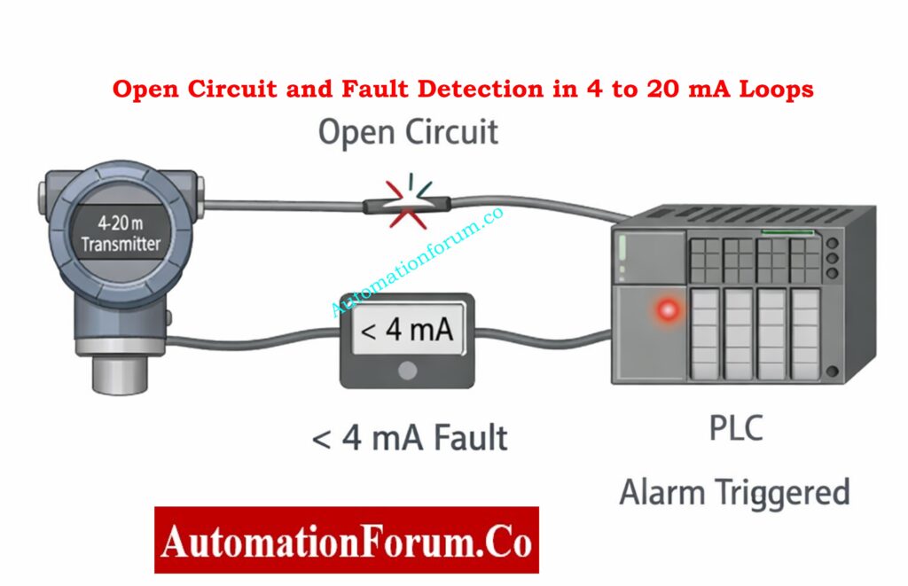
- Another big plus of the 4 to 20 mA signal is that it may plainly show when there is an open circuit or a malfunction.
- The signal stays between 4 mA and 20 mA when everything is working normally. If something goes wrong outside of this range, it will be obvious right away.
- Technicians should remember the following things:
How Control Systems Detect Failures
- If the current is less than 4 mA, it usually means that there is a problem, like a damaged wire, a loose termination, or a power outage.
- Modern PLCs and DCS systems are set up to automatically sound alarms when they detect conditions that are too low.
- Finding problems early stops wrong control actions from happening because of bad data.
- This built-in diagnostic feature makes the plant more reliable and safe to work in..
Hz to 4–20 mA Conversion Calculator for Speed & Flow Signals: Frequency(Hz) to 4 to 20 mA Signal Conversion Calculator
Ground Loop Risks in 4 to 20 mA Systems
- Even if the 4 to 20 mA signal is strong, bad grounding might still cause problems.
- When the signal loop is grounded at more than one place, it creates a ground loop. This makes unwanted routes for current that mess up the measuring signal.
- Common signs of ground loops are readings that change, signals that drift, and noise that can’t be explained.
Preventing Ground Loop Problems
- To avoid problems with ground loops, technicians should do the following.
- Make sure that the signal loop is only grounded at one location.
- If you need to, use signal isolators or isolation barriers.
- Don’t use ad hoc grounding methods; instead, follow the rules for plant grounding.
- Even with a strong current loop, proper grounding is necessary for steady and accurate measurements.
4–20 mA to 3–15 psi Converter for I/P and Pneumatic Systems: 4–20 mA to 3–15 psi Signal Conversion Calculator
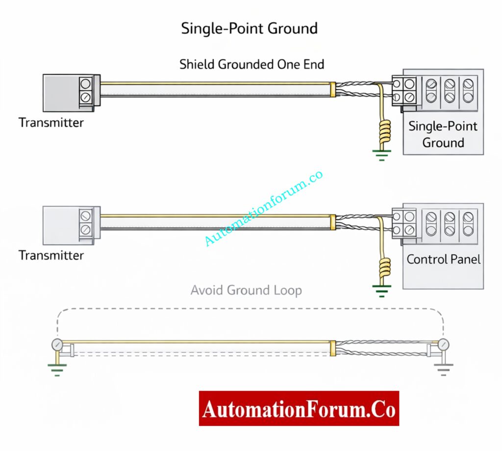
Correct Shielding Practices for 4 to 20 mA Cables
- People often use shielded cables for 4 to 20 mA signals to keep electromagnetic interference from happening. But shielding won’t work if it’s not done well.
- The most crucial guideline is to only ground the cable shield at one end, usually the control panel side.
- Technicians should keep the following important considerations in mind.
- If you ground both ends of the shield, you can make a ground loop through the shield itself.
One-End Shield Grounding Rule
- A single point shield ground keeps noise out without causing interference.
- The shield should stay in place all the way down the cable line.
- Using the right shielding techniques makes signals much clearer and systems much more stable.
How to Calculate Temperature Transmitter 4–20 mA Output (With Examples): How to Calculate Temperature Transmitter 4-20mA Output Using Linear Equation and Percentage Method ?
Importance of Proper Scaling in 4 to 20 mA Signals

- A 4 to 20 mA signal only makes sense if the transmitter and control system are set up correctly.
- Scaling tells you how a certain current value relates to an engineering unit, such a bar, a degree Celsius, or a cubic meter per hour.
- Wrong scaling can cause big difficulties with how things work.
- Here are some important things to think about when scaling.
- The PLC or DCS must have the same range set for the transmitter.
- It is important to check the zero and span values during commissioning.
- You need to compare the displayed values against known reference signals.
- Scaling correctly makes sure that operators see the right information and that the control logic works as it should.
Why Scaling Errors Cause Serious Problems
- When the transmitter range and control system setup don’t match, the readings are wrong.
- During commissioning, you need to check the zero and span.
- Accurate scaling makes ensuring that display values are right and control actions are correct.
How to Simulate a 4–20 mA Signal Using a Loop Calibrator: How to simulate 4-20ma signal with Loop Calibrator ?
Effect of Cable Resistance on 4 to 20 mA Signals
- In voltage-based systems, the resistance of the cable has a direct effect on how accurate the signal is. Longer cables and lower conductor diameters make voltage drop and measurement inaccuracy worse.
- In a 4 to 20 mA system, the resistance of the cable does not change the current value in the loop.
Practical Benefits for Technicians
- This has a number of useful benefits.
- You can utilize standard industrial cables without losing accuracy.
- Long cable runs do not change the value that is measured.
- Because you don’t need special low-resistance wires, the cost of installation goes down.
- However, technicians must make sure that the total loop resistance stays within the voltage range that the transmitter and power supply can handle.
Why 4–20 mA & 3–15 psi Are Used Instead of 0–20 mA & 0–15 psi: Why not use 0-20mA & 0-15psi instead of 4-20mA & 3-15psi?
Industry Standard Signal
- Even though digital communication technologies have come a long way, the 4 to 20 mA signal is still the most dependable and frequently used industry standard.
- Almost every transmitter, PLC, DCS, and indicator in the world supports it. It is straightforward to test, easy to fix, and has been used in real-world situations for decades.
- 4 to 20 mA is still the main output for modern smart transmitters. They often use digital communication for diagnostics and settings as well.
4–20 mA to 1–5 V & PLC 16-Bit Raw Count Calculator: Calculator for 4-20mA Signal to 1- 5Volt and PLC 16-bit Raw Count Values
Why 4 to 20 mA Remains the Industry Standard Signal
- Even though digital communication protocols are growing quickly, the 4 to 20 mA signal is still the norm for analog measurement around the world.
- There are a few reasons why it is still the best.
- It is easy to use, dependable, and supported by everyone.
- Using simple equipment like multimeters and loop calibrators makes it easy to fix problems.
- It works well in tough industrial settings.
- Most modern smart transmitters still use 4 to 20 mA as their main output. They often employ digital communication for diagnostics and settings as well.
- The 4 to 20 mA signal will stay useful for a long time because it is both simple and reliable.
Complete Guide to Troubleshooting 4–20 mA Current Loops: How to do troubleshooting of a 4-20mA loop?
Key Lessons for Technicians
- It’s not a coincidence that the 4 to 20 mA signal has been around for so long. It is the culmination of decades of real-world experience, safety needs, and good engineering practices.
- Technicians that know the basics of this signal are better able to set up, test, fix, and keep industrial instrumentation equipment running.
- Technicians can avoid making frequent mistakes and make sure that their measurements are precise, consistent, and reliable by learning about things like live zero, noise immunity, grounding, shielding, and scaling.
- In an industry where safety and performance are important, the 4 to 20 mA signal shows that the simplest answer is often the best.
The 4 to 20 mA signal’s ongoing success is due to good engineering, not tradition. In true industrial settings, nothing else can equal its reliability, capacity to find faults, noise immunity, and ease of use.
Technicians must know these ten rules inside and out. If you know the basics of 4 to 20 mA, you’ll be able to install things better, fix problems faster, have fewer process upsets, and run your plant more safely.
The 4 to 20 mA signal shows that a simple, well-designed system may stay strong for decades in a world full of complicated technologies.
Accurate 4–20 mA to Process Value (PV) Scaling Calculator: 4-20mA to PV scaling calculator
FAQ On 4 to 20 mA signal
What is a 4 to 20 mA signal?
A 4 to 20 mA signal is an analog current signal that sends measurements of things like pressure, temperature, flow, and level in industrial automation.
In this system, 4 mA represents no value and 20 mA means full value. The current changes between these two boundaries depending on how the process is going. Many people use it because it is dependable, precise, and works well in factories.
How to check 4 to 20 mA in a multimeter?
To use a multimeter to check a 4 to 20 mA signal:
Change the multimeter to DC current (mA) mode.
Connect the multimeter in series with the circuit by opening the loop.
Turn on the loop and look at the value on the screen.
A normal signal will be between 4 mA and 20 mA.
A reading close to 0 mA usually suggests there is an issue with the wiring or the transmitter.
What is a 4-20 mA analog signal?
A 4-20 mA analog signal is a signal that is always on and off, with the current smoothly changing between 4 mA and 20 mA to show a process value.
The signal can take any value in the range, not simply ON or OFF, hence it is called analog. This is great for illustrating real changes in a process.
How to read a 4 to 20 mA signal?
The current is turned into a process value such that a 4 to 20 mA signal can be read.
For example, if a transmitter range is 0 to 100 units:
- 4 mA represents 0
- 20 mA represents 100
- 12 mA represents 50
PLCs and indicators do this conversion automatically when scaled correctly.
Is 4/20 mA signal AC or DC?
A 4 to 20 mA signal is not AC; it is DC.
It gets its power from a DC power source, which is commonly 24 V DC. The transmitter adjusts the level of the DC current to show the measurement.
How to calculate 4 to 20 mA formula?
The simple formula to calculate the process value is:
(Current − 4) ÷ 16 × Range
Example
If the range is 0 to 200 and the current is 12 mA:
(12 − 4) ÷ 16 × 200 = 100
This formula helps convert current into the actual measured value.