- Transmitter
- Standard Signal
- List some of wiring techniques in transmitter wiring.
- Loop Powered transmitter
- How 2-wire (“loop-powered”) transmitter works as current loops?
- Features of Loop powered Instruments
- Advantages of Loop powered transmitters
- Disadvantages of Loop powered transmitters
- Benefits of using a current as an electrical signal in transmission
- What are the different ways of measuring loop current?
- Frequently asked Questions:
Transmitter
A transmitter is a device for converting the response of a primary element into a useable signal, which then transmitted either to an indicating instrument or to a controller. Thus, transmitters is said to be secondary element.
Standard Signal
- Electrical:
- 4 – 20 mA (DC current)
- Span = 20 mA – 4 mA = 16 mA
- Others: 10 – 50 mA, 1– 5 mA (DC current) 0 – 5 V, 0 –10 V (DC voltage)
- AC voltageDigital transmission
- Pneumatic:
- 3 –15 psi (20 to 100 kPa) gauge pressure range
- Span = 15 psi – 3 psi = 12 psi
- Others: 3 – 27 psi – 30 psi (more force)
List some of wiring techniques in transmitter wiring.
Some wiring techniques are
- Non-isolated current source & current sink transmitter
- 4-wire Fully isolated transmitter
- 2-wire loop powered transmitter
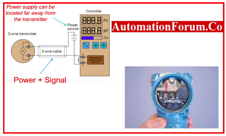
Loop Powered transmitter
- It is also called as two wired powered transmitters. Excluding the input leads, only two wires are needed. Both the transmitter’s power and the output signal are transmitted across these two cables.
- The two-wire transmitter benefits from not requiring a local power supply as a result.
- When transmitter is connected to loop-powered, analogue information is transmitted and electrical power over the same two wires of 4 to 20 milliamps DC.
- The following describes how a loop-powered transmitter is connected to a process controller:
- The transmission of process measurement data from transmitters to controllers, indicators, recorders, alarms, and other input devices is also possible via DC electric current signals.
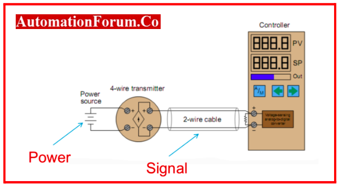
- A transmitter with two terminals for the 4-20 mA signal wires to attach to and two extra terminals for a power source is the most basic type of 4-20 mA measuring loop. They are referred to as “4-wire” or self-powered transmitters.
- To complete the loop, the transmitter’s current signal is connected to the controller’s process variable input terminals.
How 2-wire (“loop-powered”) transmitter works as current loops?
As transmitter does not have four wires, it is not a true current source. Instead, a 2-wire transmitter’s circuitry is built to function as a current regulator, capping the current in the series loop at a level that is consistent with the process measurement and relying on an external power source to drive current flow.
Remember the circuit diagram for the 4-wire transmitter for reference. In contrast to the 4-wire transmitter’s current source, which actually acts as an electrical source, this loop-powered transmitter’s current “source” actually acts as an electrical load.
Example circuit of Loop Powered 4-20mA Transmitter
- The minimum terminal voltage and current available at a loop-powered transmitter’s two terminals provide the device with the power it needs to function.
- The transmitter must always have at least 19 volts accessible at its terminals, given that the average source voltage is 24 volts DC and that a maximum of 5 volts DC can cross the controller’s 250 ohm resistor.
- The transmitter needs at least 4 mA of current to run on given the bottom end of the 4-20 mA signal range. So, while controlling current to communicate the process measurement, the transmitter will always have a specific minimum amount of electrical power available to run on.
- The loop-powered transmitter circuitry seems like this on the inside:

- The whole sensing, scaling, and output conditioning circuitry for the transmitter must be designed to run at low terminal voltages and with DC current draws no greater than 4 mA.
- In order to make the total current representative of the process measurement, the transmitter circuitry uses a transistor to shunt (bypass) excess current as necessary from one terminal to the other.
- To enable the transmitter to cover the entire 4 to 20 milliamp signal range, loop currents greater than 4 mA must be generated.
- When the transmitter needs to regulate loop current at a value of 16 mA to reflect a state of 75% process measurement, for example, and its internal working current is just 3.8 mA.
- Early current-based industrial transmitters employed a different current signal standard: 10 to 50 milliamps DC, as they could not function at such low electrical power levels.
- These transmitters’ loop power supplies could deliver up to 90 volts of power, which was sufficient for the transmitter. Because of safety issues, the 10-50 mA standard was impractical for some industrial installations, while the 4-20 mA standard, with its lower power consumption, was suitable for almost all types of process transmitters.
Features of Loop powered Instruments
- Also called as 2 wire connection
- It does not require independent power source and power is obtained from the signal circuit
- Less power is used, which limits the capability of the instrument
- More simplistic, easier to wire
- Offer a lot of flexibility of ability to install instrument without another power source
Advantages of Loop powered transmitters
- It has a minimal power requirement
- The transmitter requires two cable cores.
Disadvantages of Loop powered transmitters
- Since this setup still draws some current during a fault condition, transmitter discrete fault signaling cannot be set to 0 mA.
- For control panels that require a 0mA signal for a fault indicator, this design is not suitable.
Benefits of using a current as an electrical signal in transmission
- The transmitter acts as a current source, allowing multiple loads to be connected in series up to a predetermined limit on total resistance.
- The length and resistance of the transmission circuit have no bearing on the signal sensitivity.
- Very frequently, the power source for the transmission circuit can be sited inside the receiver, necessitating the use of only a two-wire connection.
- As long as the circuit resistance upper limit is not exceeded, electrical signals can travel farther and with less lag, can be made compatible with master digital computers, and can handle numerous input signals distance and less time lag;
- signal can be made compatible with master digital computer;
- handle multiple-input signal
What are the different ways of measuring loop current?
- Standard milliammeter
- Clamp-on milliammeter
- Test diodes
- Shunt resistors
Standard milli-ammeter of loop current measuring
A DC milliampere multimeter is the obvious tool for troubleshooting since the signal of interest is an electric current in an instrumentation current “loop” circuit.
Drawback of using a milli-ammeter
- The circuit must be “broken” in order to connect the current meter in series with it, which causes the current to decrease to 0 mA until the metre is connected and then rise once more when it is unplugged.
- Stopping the current disrupts the flow of information, whether it is a process measurement or a command signal to a final control device. This will harm a control system if we are not ready.
How to overcome disruption due to breaking the loop?
- One needs to alert that the signal will be broken at least twice, dropping to -25% each time, before ‘breaking the loop’ to connect their meter.
- To prevent disrupting the process by changing the final control element in reaction to the unexpected loss of PV signal, the controller should be switched to manual mode if the signal to be interrupted is coming from a process transmitter to the controller.
- Process alerts ought to be momentarily disabled. Disable process shutdown alarms, if this signal drives them so that nothing shuts down when the signal is interrupted.
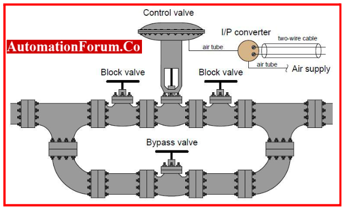
- If the current signal to be interrupted is a command signal from a controller to a final control element, the final control element must either be manually overridden to keep a constant value while the signal fluctuates or bypassed by another device(s).
- Opening a bypass valve and closing at least one block valve is normal if the final control element is a control valve.Control valve with bypass & Block valve is shown below.

Clamp-on milliammeter for loop current measurement
- Clamp-on milliammeters can magnetically measure 4-20 mA signals without interrupting them.
- Modern Hall-effect sensors can detect weak magnetic fields from modest DC currents in wires.
- Hall-effect ammeters clamp around the wire without breaking the circuit, making them non-intrusive.
- The milliammeter displays loop current (3.98 mA) and converts it into a percentage of range, following the 4 to 20 mA signal standard. Strong magnetic fields can cause clamp-on milliammeter errors.
Loop current measurement with “test” diodes
- When the loop circuit was commissioned, a rectifying diode was inserted to measure a 4-20 mA signal without stopping it.
- The loop can have a forward-biased “test” diode anywhere in series.
- When forward biased, the diode drops about 0.7 volts. The following schematic illustration depicts a diode in a 2-wire transmitter loop circuit:
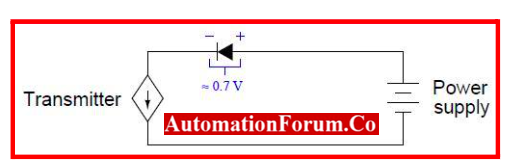
- However, if a milli ammeter is connected in parallel with this diode, its low input resistance “shorts past” the diode and prevents any significant voltage drop across it.
- The diode conducts 0 mA without the forward voltage drop, allowing the entire loop current to pass through the ammeter:
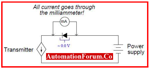
- The 0.7 volt drop that occurs when the milliampere is removed appears to turn on the diode, resuming full loop current flow. A technician can measure current without being concerned about false process variation signals, alarms, or process disruption because the loop current is never stopped.
- A diode is places at near junction box between terminal strip, or transmitter. Some process transmitters have “Test” connections for this. These “test” connectors link the milli ammeter to a transmitter diode.
- Without unplugging any wires, an ammeter may directly measure the 4-20 mA current signal at these two test sites.
Using shunt resistors to measure loop current
- Shunt resistors measure loop current. A precision resistor in series can measure current in a 4-20 mA instrumentation circuit non-invasively. If the resistance value is known, the technician can apply Ohm’s Law to calculate current:
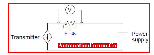
- Shunt resistors measure current in electronics. For current measurement without voltage drop, shunt resistor values are usually minimal. Because the increased voltage loss (1 to 5 volts, depending on the current signal level) may “starve” loop-powered instruments, 250 ohm resistors are rarely used as diagnostic shunt resistors.
- In 4-20 mA current loops, technicians may insert 1 ohm shunt resistors at appropriate spots to measure loop current.
Frequently asked Questions:
What function does the current loop serve?
A current loop has the objective of measuring or analyzing environmental variables like temperature, pH, or others. It can also be used to address problems with grounding and other system parts.
How self powered is different from loop powered?
The fact that loop powered instruments don’t require independent power is the primary distinction between loop-powered instruments and self-powered instruments.
What is 4-20 mA loop power?
The 4-20 mA current loop has been the accepted norm in the industry for electronic control and signal transmission in control systems. A current loop uses a dc power source to provide the current signal, which then flows in a series circuit through the transmitter, controller, and back to the power source.
Why is 4-20 mA used instead of 0-20 mA?
- Because it is simpler to locate a broken wire with the 4-20 mA signal than the 0-20 mA signal, so 4-20mA is preferred.
- If the current detected in a 4-20 mA transmitter is zero, an error signal will be released.