- What Is Alarm Setpoint Field Validation in Process Instruments?
- Why Alarm Setpoint Validation Is Important for Process Safety and Reliability
- Alarm Setpoint Field Validation Procedure Step by Step
- Alarm Setpoint Field Validation Checklist for Process Instruments
- Detailed Explanation of Critical Alarm Validation Checks
- Practical Example of Level Transmitter High Alarm Validation
- Common Mistakes in Alarm Setpoint Field Validation
- Best Practices for Alarm Validation in Instrumentation and Control
- Who Should Use This Alarm Validation Checklist?
- When to Perform Alarm Setpoint Field Validation
- Benefits of Alarm Setpoint Field Validation Checklist
- Alarm Setpoint Field Validation Checklist Excel Sheet
- Frequently Asked Questions About Alarm Setpoint Validation
What Is Alarm Setpoint Field Validation in Process Instruments?
Importance of Alarm Systems in Process Industries
Alarm systems are one of the most important protection layers in process industries such as oil and gas, chemical, power generation, pharmaceuticals, and water treatment. A well-designed alarm gives the operator timely and meaningful warning so corrective action can be taken before the process becomes unsafe or unstable.
Why Alarm Configuration in DCS and PLC Is Not Sufficient
However, configuring an alarm in a DCS or PLC is only part of the job. It is also important to test the alarm in the field to make that it goes off at the right process value, shows up correctly, and works exactly as planned when it is in use. Even if an alarm is set up correctly, it could fail when it matters most if it isn’t validated in the field.
Impact of Incorrect Alarm Settings on Process Safety
If the alarms are put up wrong, they can go off when they shouldn’t, miss alarms, flood alarms, confuse operators, and take longer to respond to situations. Many industrial accidents have happened because alarms weren’t managed well, which made the conditions dangerous and the plant less reliable. That is why alarm validation should never be treated as a one-time commissioning task. It must be part of startup, maintenance, modification, and periodic audit activities.
Plant Maintenance Checklist: Maintenance Checklist
Role of Alarm Validation in Improving Plant Reliability
Alarm setpoint field validation helps confirm that alarm limits, priorities, delays, annunciation, and reset behavior are all working correctly.It makes ensuring that alarms are useful, informative, and in line with process safety rules.
Master PLC Alarm Trip Docs: PLC Alarm and Trip Documentation Procedure – EPC PLC Automation Engineer Guide
Overview of ISA 18.2 and IEC 62682 Standards
Standards like ISA 18.2 and IEC 62682 stress alarm management based on the plant’s lifespan. This means that alarms are designed, put in place, watched, and kept up with throughout the plant’s life.
Alignment of Alarm Validation with Process Safety Requirements
Alarm setpoint field validation is the process of checking that an alarm set up in the control system goes off at the right process value and works as it should in real or simulated field settings.
In simple terms, it means making sure that the alarm works in real life and not only on paper or in the control logic.
Alarm Setpoint Field Validation Meaning and Purpose
The engineer confirms that during field validation:
- the alarm triggers at the correct setpoint,
- the alarm appears correctly in the DCS or HMI,
- the operator receives the right message and priority,
- the alarm resets properly after the process returns to normal,
- the alarm does not chatter or generate nuisance signals.
Difference Between Alarm Configuration and Field Validation
| Type | Description |
| Configuration validation | Checking alarm logic, setpoints, tags, and priorities inside the DCS or PLC |
| Field validation | Testing alarm behavior using actual or simulated process conditions |
The system database may show that the configuration is right, but field validation shows that the real instrument and process response match what was planned.
NFPA 72 Fire Alarm Setup: Method Statement for Addressable Fire Alarm System Installation, Testing and Commissioning as per NFPA 72
Why Alarm Setpoint Validation Is Important for Process Safety and Reliability
Alarm validation has a direct effect on the safety of the process, the performance of the operators, and the reliability of the plant.
How Improper Alarm Settings Cause False or Missed Alarms
The purpose of alarms is to let operators know when anything is wrong and needs to be fixed. If alarms are not validated properly:
- critical alarms may fail to trigger,
- operators may miss dangerous conditions,
- safety incidents may occur,
- protective actions may be delayed.
Solenoid Valve Selection Guide: Essential Checklist for Selecting the Right Solenoid Valve for Your Application
Impact of Alarm Flooding on Operator Performance
Poor alarm management can also damage day-to-day operations. Common problems include:
- alarm flooding that overwhelms the operator,
- nuisance alarms that reduce confidence in the system,
- repeated alarms that distract attention,
- delayed response during real process upsets.
A properly validated alarm system helps operators focus on what matters most and respond correctly when the process moves outside safe limits.
Critical Alarm Trip Setpoint Guide: Alarm & Trip Setpoint List in Instrumentation Engineering: The Most Critical Document for Plant Safety
Alarm Setpoint Field Validation Procedure Step by Step
A structured approach is necessary to perform alarm validation effectively. The goal is not just to see the alarm appear, but to verify that every part of the alarm response is correct.
Step 1: Gradually Change the Process Variable
Slowly change the process variable up or down so that you can see the exact point at which it triggers. It can be hard to check the alarm point correctly when things change quickly.
Step 2: Verify the Alarm Trigger Point
Make sure the alarm goes off right at the setpoint you set. Any offset could mean that there are problems with scaling, logic, or the instruments.
Step 3: Check Alarm Priority and Alarm Classification
Check to make sure that the priority is the same as what is written in the alarm rationalization document. In general:
- High priority is used for alarms that are very vital for safety,
- Medium priority is used for alarms that are important for operations,
- Low priority is used for alarms that are just for information.
Step 4: Confirm Tag Number, Instrument Identification, and Description
Make sure that the following things are correct:
- tag number,
- alarm description,
- engineering units,
- loop or instrument identification.
An operator can get confused and respond less well if a tag is inaccurate or the description is not clear.
ISO Calibration Audit Checklist: Internal Audit Checklist for ISO Process Instrument Calibration in Process Industries
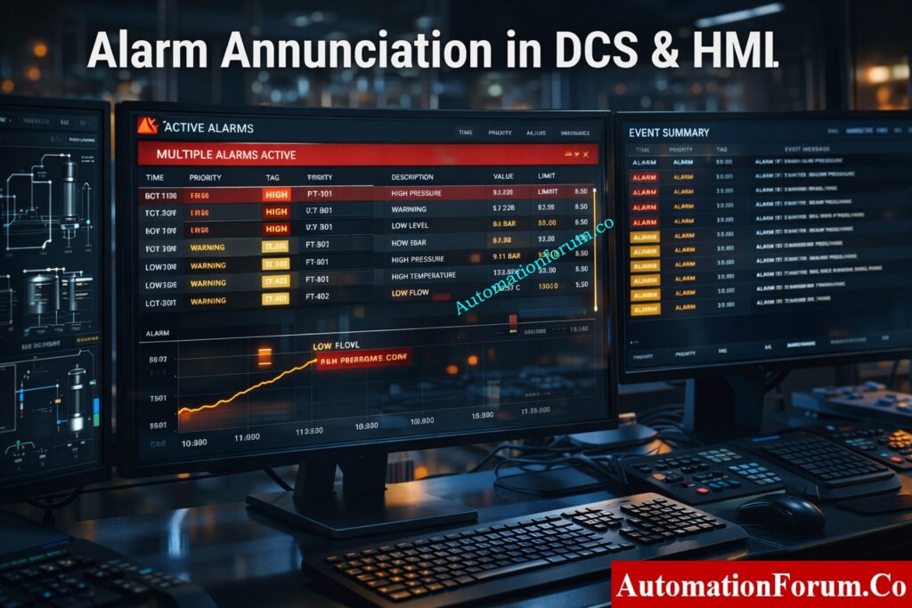
Step 5: Validate Alarm Annunciation in DCS and HMI
Check that the alert shows up correctly in:
- the DCS,
- the HMI,
- the event summary or alarm summary page.
The operator might not see the alarm in time if it isn’t easy to see or understand.
Fire Alarm Battery Sizing Tool: Fire Alarm Battery Size Calculator – Professional Tool for Accurate Backup Power Sizing
Step 6: Check Alarm Reset and Recovery Behavior
Check to see if the alert clears correctly after the procedure goes back to normal. The way the reset works must be the same as the logic that was meant to be used.
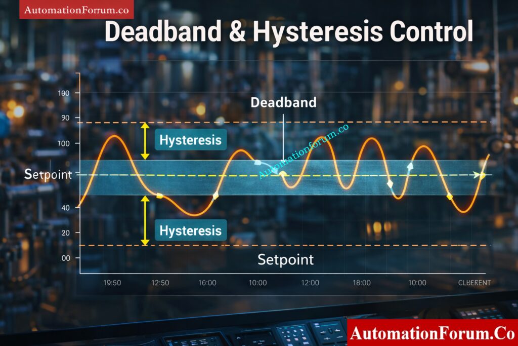
Step 7: Verify Deadband and Hysteresis Settings
Deadband stops the alarm from going off and on again and again near the setpoint. If the hysteresis isn’t set up right, the alarm could chatter and make the operator tired for no reason.
Step 8: Test Alarm Delay Time Settings
Look at the settings for both the on-delay and off-delay.
- On-delay stops short transients from setting off false alarms.
- Off-delay helps make the reset procedure more stable.
Step 9: Confirm Alarm Logging and Historian Recording
Make sure the alarm is written down in:
- the alarm history,
- event logs,
- historian or audit records.
This information is useful for figuring out problems, checking performance, and making sure rules are followed.
Detector Coverage Calculator Tool: Fire Alarm Detector Coverage Calculator – Professional Excel Tool for Accurate Detector Placement
Alarm Setpoint Field Validation Checklist for Process Instruments
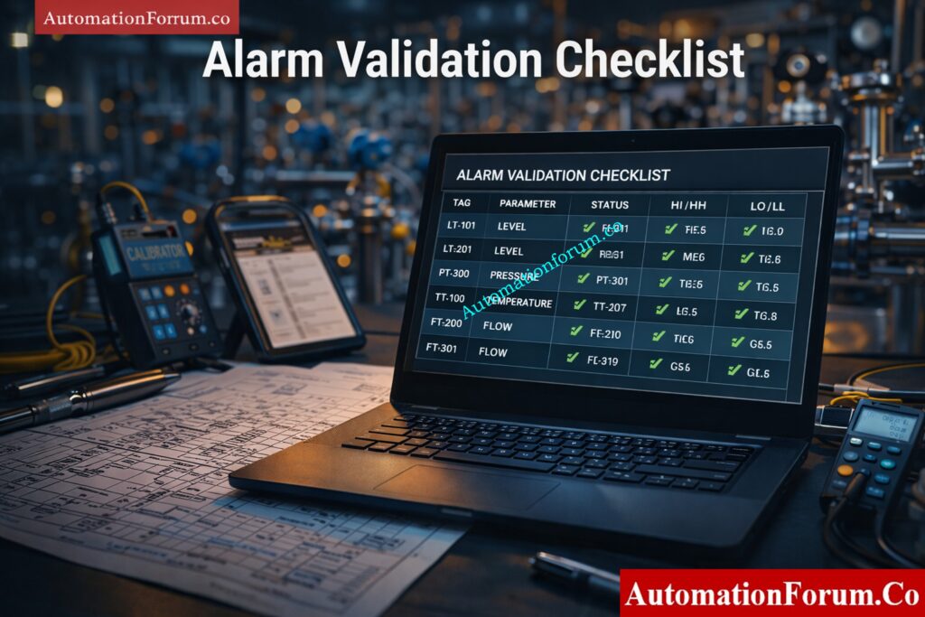
Use the following checklist during field validation to make sure that the alert works as it was meant to.
| Sl No | Check Point | Description | Expected Result | Status | Remarks |
| 1 | Tag verification | Verify instrument tag with P&ID | Exact match | ||
| 2 | Instrument identification | Confirm correct field device | Correct device linked | ||
| 3 | Signal integrity | Check input signal quality | Stable signal | ||
| 4 | Engineering units | Verify unit consistency | Correct units displayed | ||
| 5 | Alarm setpoint | Check configured value | Matches design | ||
| 6 | Alarm type | Verify high, low, HH, LL | Correct classification | ||
| 7 | Alarm priority | Validate priority | Matches rationalization | ||
| 8 | Alarm message | Check description clarity | Clear and actionable | ||
| 9 | Alarm trigger point | Simulate PV change | Triggers at correct value | ||
| 10 | Repeatability | Test multiple times | Consistent triggering | ||
| 11 | Deadband check | Verify hysteresis | No chattering | ||
| 12 | On delay | Verify activation delay | Matches configuration | ||
| 13 | Off delay | Verify reset delay | Matches configuration | ||
| 14 | Annunciation | Check HMI display | Visible and audible if required | ||
| 15 | Alarm banner | Verify alarm listing | Correct display | ||
| 16 | Acknowledgment | Test acknowledgment | Proper logging | ||
| 17 | Reset behavior | Reduce PV | Clears correctly | ||
| 18 | Latching logic | Verify latch function | Works as designed | ||
| 19 | Alarm shelving | Check suppression | Functions correctly | ||
| 20 | Interlock logic | Verify trip action | Interlock activates | ||
| 21 | Cause and effect | Cross-check logic | Matches matrix | ||
| 22 | Operator response | Validate operator action | Correct response | ||
| 23 | Alarm logging | Check event log | Recorded correctly | ||
| 24 | Historian recording | Verify storage | Data logged | ||
| 25 | Alarm flooding | Simulate multiple alarms | No overload | ||
| 26 | Communication delay | Check signal delay | Acceptable response time | ||
| 27 | Fail-safe condition | Simulate failure | Alarm generated | ||
| 28 | Sensor fault | Disconnect sensor | Fault alarm generated | ||
| 29 | Redundancy check | Verify backup signals | Proper switchover | ||
| 30 | Power failure | Simulate power loss | Proper behavior | ||
| 31 | Alarm inhibition | Check override logic | Works correctly | ||
| 32 | Alarm grouping | Verify grouping | Proper grouping | ||
| 33 | Color coding | Check color scheme | Matches priority | ||
| 34 | Alarm sound | Verify audio alert | Correct tone | ||
| 35 | Escalation logic | Check escalation | Works correctly | ||
| 36 | KPI compliance | Verify alarm rate | Within limits | ||
| 37 | Rationalization compliance | Cross-check alarm list | Only valid alarms | ||
| 38 | Documentation | Verify records | Updated properly | ||
| 39 | MOC compliance | Check change control | Proper approval | ||
| 40 | Final approval | Engineer sign-off | Approved |
Industrial Alarm Management Mastery: Guide to Industrial Process Alarms in Control Systems: Types, Classifications, and Management Methods
Detailed Explanation of Critical Alarm Validation Checks
Tag and Instrument Verification in the Field
This is the first and one of the most important steps in the validation process. Many alarm issues occur simply because the alarm is linked to the wrong instrument or tag. Always cross-check the alarm with:
- the P&ID,
- loop diagrams,
- the DCS database,
- instrument drawings and datasheets.
If the tag is wrong, the entire validation process becomes unreliable.
Alarm Setpoint Accuracy and Design Basis Compliance
The alarm setpoint must match the approved design basis, including:
- instrument datasheet,
- alarm rationalization report,
- process safety requirements,
- operating philosophy.
Incorrect setpoints can cause false alarms or missed alarms, both of which are dangerous in process operations.
Alarm Priority Validation According to Rationalization
Alarm priority must reflect the actual risk level of the condition. A safety-critical alarm should not be treated the same way as a routine advisory alarm. Priority assignment should always be based on rationalization and operator action requirements.
Deadband and Hysteresis for Nuisance Alarm Prevention
Deadband is necessary to prevent chattering around the setpoint. Without deadband, the alarm may repeatedly activate and clear, creating unnecessary noise and reducing operator trust. A properly tuned deadband improves stability and usability.
Alarm Delay Verification for Stable Operation
Alarm delay is often used to avoid nuisance alarms caused by short process fluctuations.
- On-delay stops the alarm from going off when there are short spikes.
- Off-delay prevents rapid clearing when the signal is unstable.
The delay must be carefully adjusted so it supports reliability without slowing down real protective response.
Alarm Annunciation and Operator Interface Validation
The alarm must be easy to see and understand on the operator interface. It should be:
- visible,
- properly color coded,
- clearly labeled,
- audible if required by site design.
Poor annunciation reduces operator effectiveness and can lead to missed responses.

Interlock and Shutdown Logic Verification
Alarm Logging, Historian and Audit Trail Requirements
Every important alarm should be recorded for:
- audit trail,
- root cause analysis,
- performance review,
- regulatory or internal compliance.
Historical records are essential for identifying recurring alarm problems and improving alarm management over time.
Operator Response Validation for Actionable Alarms
An alarm is useful only when the operator knows what action is required. During validation, confirm that the operator response is clearly defined, understood, and aligned with the operating procedure.
Fail-Safe Testing for Signal Loss and Fault Conditions
Validation should encompass aberrant and failure scenarios, rather than solely typical process modifications. Some examples of test situations are:
- transmitter open circuit,
- short circuit,
- signal loss,
- communication failure,
- power interruption.
The design should explicitly spell out how the system is supposed to work, and the validation should make sure it does.
Alarm flooding and system performance
Alarm flooding happens when there are too many alarms in a short amount of time, making it hard for the operator to decide what to do first. During validation, set off several alerts and make sure the system is still easy to use and that important alarms are still visible.
Alarm rationalization compliance
Every alarm should have a clear reason for going off, a specific way for the operator to respond, and a valid priority and setpoint. If the alarm does not meet those criteria, it should not exist in the system.
DCS Alarm Control Checklist: DCS Alarm Management Checklist
Practical Example of Level Transmitter High Alarm Validation
A simple practical example helps explain how field validation is performed in real plant conditions.
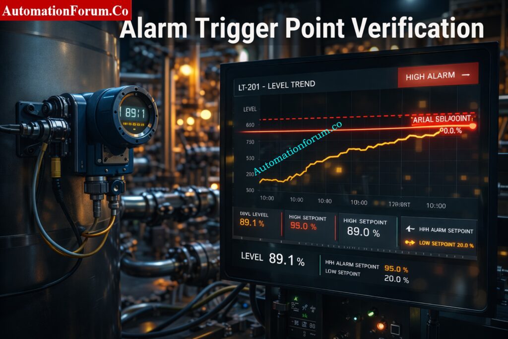
Level Transmitter LT-101 Alarm Setpoint Example
- Instrument: Level Transmitter LT-101
- Range: 0 to 100 percent
- High alarm setpoint: 80 percent
- High-high alarm setpoint: 90 percent
High Alarm and High-High Alarm Field Test Procedure
Step 1: Simulate level increase
Use process filling or a site-approved simulation approach to slowly raise the level from about 60% to 100%.
Step 2: Monitor the DCS display
Check the trend of the process value and make sure that the level rises steadily and without any scaling problems.
Step 3: Validate the high alarm
The high alert should go off when the level reaches 80%. Check the following:
- alarm message,
- alarm priority,
- visual indication,
- audible indication if applicable.
Step 4: Validate the high-high alarm
Keep raising the level until it reaches 90%. The high-high alarm should go off and cause the necessary precautionary action, like an interlock or operator escalation.
Step 5: Verify reset behavior
Lower the level below the point where the system resets, and make sure that both alarms go off correctly.
Expected Results During Alarm Validation
This example shows that:
- the alarm triggers at the defined setpoint,
- the operator receives the correct information,
- the system behaves consistently,
- the process protection logic works as intended.
FACP Explained Simply: What is an FACP? (Fire Alarm Control Panel)
Common Mistakes in Alarm Setpoint Field Validation

Even engineers who have been doing this for a long time sometimes miss key nuances when validating alarms. Here are some common mistakes:
Incorrect Alarm Setpoint Configuration
The alarm can go off too early or too late because of mismatched units, scaling mistakes, or wrong technical conversions.
Priority Mismatch in Alarm Management
A critical alarm may be assigned low priority, or a minor advisory may be given high priority. Both situations reduce alarm quality.
Wrong Tag or Wrong Instrument Linkage
The alarm may be connected to the wrong instrument or signal source. This is one of the most serious validation failures.
Ignoring Real Field Testing
Testing only in the DCS simulation is not enough. Real field testing is necessary to confirm actual instrument behavior.
Missing Deadband Configuration
Without deadband, the alarm can go off near the setpoint and make annoying alarms.
Poor Alarm Message Design
An unclear alert message doesn’t help the operator. Every alarm should provide clear and actionable information.
Alarm Trip Priority Explained: What are alarm, trip point, and alarm priority in DCS & PLC?
Best Practices for Alarm Validation in Instrumentation and Control
Validate Alarms Under Real Field Conditions
Simulation is useful, but real field validation provides the highest level of confidence. It is important to test the alarm in real-world or simulated field settings whenever possible.
Use Trending Tools to Confirm Trigger Points
Trending helps confirm the exact trigger point and indicates how the process acts when it gets close to the alert level.
Follow Management of Change Procedures
Any changes to alarms should follow the rules for formal change control. This helps keep configuration drift from happening without documentation.
Maintain Alarm Validation Records
Keep records of:
- test results,
- engineer name,
- date and time,
- remarks,
- corrective actions.
These records help with audits and fixing problems in the future.
Eliminate Alarm Flooding and Duplicate Alarms
The system should only keep alarms that can be acted on. You should get rid of or make sense of too many or duplicate alarms.
Train Operators on Alarm Response Actions
Operators must understand:
- what the alarm means,
- what response is expected,
- when escalation is required.
Fire Alarm System Parts Guide: What are the components involved in a Fire Alarm system?
Who Should Use This Alarm Validation Checklist?
This checklist is helpful for many jobs in the process industries.
- Commissioning engineers: Used by commissioning engineers to get ready for startup and do initial validation before the plant starts running.
- DCS and PLC engineers: Used to verify alarm logic, display behavior, and control system implementation.
- Instrument technicians: Used during field testing, maintenance, and calibration activities.
- Safety engineers: Used to verify alarms tied to critical safety functions and compliance requirements.
Field Cross Check Procedure: Process Value Cross Check – Practical Field Procedures for Accurate Transmitter Validation
When to Perform Alarm Setpoint Field Validation
Alarm validation is not a one-time task. It should be performed at several stages in the plant lifecycle.
- During Commissioning and Startup: Before startup, after instrument installation, and before process handover.
- After Instrument Replacement or Re-Ranging Whenever an instrument is replaced, re-ranged, or recalibrated.
- During Shutdown, Startup, and Safety Audits: To confirm that no configuration drift or logic issue has been introduced.
- After Maintenance or Calibration: check to make sure that you are still following ISA 18.2 and IEC 62682.
Validation vs Calibration Explained: Differences Between Validation and Calibration
Benefits of Alarm Setpoint Field Validation Checklist
Improved Process Safety: Validated alarms let operators act quickly and lower the risk of dangerous situations.
- Reduced False Alarms and Nuisance Alarms: arms that create alarm fatigue.
- Better Operator Response and Decision Making: Clear messages, correct priorities, and reliable trigger points support faster decision-making.
- Compliance with ISA 18.2 and IEC 62682: Alarm validation follows ISA 18.2 and IEC 62682, which means that it enables lifecycle-based alarm management procedures that are in line with these standards.
- Improved Plant Reliability and Availability: A solid alarm system cuts down on unnecessary shutdowns and keeps processes running smoothly.
Fire Alarm Panel Working: What is a Fire alarm control panel and how does it work?
Alarm Setpoint Field Validation Checklist Excel Sheet
Download a professionally created and fully adorned Excel sheet that instrumentation engineers can use to check alarm setpoints in real-world situations. This template is ready to use and helps make things more accurate, cut down on false alarms, and make sure that industry standards are met.
HMI Alarm Basics: Human Machine Interface Alarms (HMI Alarms)
Frequently Asked Questions About Alarm Setpoint Validation
What is alarm setpoint validation?
It is the process of checking that an alarm goes off at the right process value and works correctly in real-world settings.
What is alarm rationalization?
It is the process of reviewing alarms to make sure they are necessary, prioritized correctly, and actionable.
What is alarm flooding?
Alarm flooding is a condition where too many alarms occur in a short time, making it difficult for the operator to respond effectively.
What is deadband in alarms?
Deadband is a small range around the setpoint that prevents chattering and repeated alarm activation.
What is an alarm setpoint?
An alarm setpoint is the preset value of a process variable at which an alarm becomes active and alerts the operator to an abnormal condition. In alarm management, the setpoint is documented along with the alarm type, cause, consequence, and operator action.
What is the alarm and setpoint list?
What’s the difference between LD1 and LD2?
In fire alarm terminology, LD1 gives maximum life protection with detectors throughout most of the premises, while LD2 provides additional protection mainly on escape routes and in high-risk rooms. The exact layout can vary by code and building type.
Alarm Management Basics: What is Alarm management?
What are the 5 mandatory alarms of ECDIS?
The five commonly cited mandatory ECDIS alarms are: crossing the safety contour, deviation from route, position/heading/speed source lost, approaching a critical point on the route, and different geodetic datum. These are set out in the IMO ECDIS performance standards
Which standard governs alarm management?
ISA 18.2 and IEC 62682 are the primary standards for alarm management.
Fire Alarm Panel Types: What is Fire Alarm control panel? What is Sub Fire Alarm Control Panel?
Alarm setpoint field validation is a critical engineering activity that directly affects process safety, operational efficiency, and plant reliability. It confirms that alarms trigger at the right time, display the right information, and guide the operator to take the correct action.
A well-structured validation checklist helps engineers verify alarm performance in a disciplined and repeatable way. When combined with alarm rationalization, proper documentation, and lifecycle-based management, it reduces nuisance alarms, prevents alarm flooding, and improves operator effectiveness.
Alarm validation should never be limited to startup or commissioning alone. It must remain an ongoing part of maintenance, change control, audits, and safety reviews.
The core message is simple: a validated alarm is a reliable alarm, and a reliable alarm is essential for safe and stable plant operation.
Refer the below link for the Advanced Integrated Field Instrument Reliability & Cyber-Secure Maintenance Checklist for Smart Process Plants