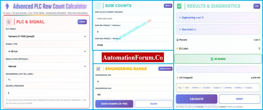
⚡ Advanced PLC Raw Count Calculator
PLC & Signal
Raw Counts
Engineering Range
Results & Diagnostics
Analog Fault Simulation
Simulate analog-wire faults or non-standard mA values. The module maps mA → raw using current rawMin/rawMax mapping.
Advanced / Preset Controls
These presets are editable — change raw min/max if your module uses a different mapping.
- Siemens rated current range commonly represented as 0 → 27648 for many AI modules.
- S7-1200 examples often use 5530 → 27648 for 4–20 mA mapping where lower raw values are reserved for diagnostics — adjust if needed.
- What is a PLC Raw Count Calculator?
- Why Raw Count Scaling is Critical in PLC Systems
- PLC Internal Scaling Blocks: An Overview
- Comparison: PLC Raw Count Calculator vs PLC Internal Scaling Blocks
- Advantages of Using a PLC Raw Count Calculator
- Mathematical Formula Used for PLC Raw Count Scaling
- Use-Case Example 1: Pressure Transmitter Scaling in PLC
- PLC Raw Count Values and Engineering Units
- Use-Case Example 2: Flow Transmitter Scaling in PLC
- Flow Measurement Using 4-20 mA Signal
- Use-Case Example 3: Temperature Transmitter Scaling in PLC
- Analog Fault Simulation Using a PLC Raw Count Calculator
- PLC Raw Count Calculator in Commissioning and FAT
- PLC Raw Count Calculator in Maintenance and Troubleshooting
- PLC Raw Count Calculator for Training and Skill Development
- Best Practices for Using a PLC Raw Count Calculator
- Why Every Automation Engineer Should Use a PLC Raw Count Calculator
- FAQ on PLC Raw Count and Analog Scaling
Programmable Logic Controllers (PLCs) don’t immediately grasp things like temperature, pressure, flow, or level in industrial automation systems. PLCs process raw digital counts that come from analog input modules instead. Before these raw data may be used for monitoring, control, alarms, and safety logic, they need to be correctly changed into engineering units.
This is where a PLC Raw Count Calculator becomes a must-have tool for engineers. Even while newer PLC systems include built-in scaling instructions, experienced automation professionals still use external raw count calculators to check, confirm, and fix problems with analog signal scaling.
This article goes into great detail on the differences between PLC internal scaling blocks and a PLC Raw Count Calculator. It then gives real-world examples of how to use these tools for pressure, flow, and temperature applications. Finally, it gives useful tips for commissioning, maintaining, and troubleshooting.
Instantly Calculate Coriolis Mass Flow (Used by Process Engineers): Coriolis Mass Flow Calculator – Complete Guide for Instrumentation & Process Engineers
What is a PLC Raw Count Calculator?
Using linear scaling math, a PLC Raw Count Calculator turns raw analog input values from a PLC into useful engineering units. It also lets you get from engineering values to raw counts in the opposite direction.
Analog input modules turn electrical signals like 4–20 mA or 0–10 V into digital form and then give you raw counts. These numbers are based on:
- PLC manufacturer
- Analog module resolution
- Signal type
- Diagnostic reserve ranges
The calculator uses the same scaling method that PLCs use internally, so the conversion is clear and can be checked.
Predict Control Valve Noise in Seconds (IEC 60534 Tool): Control Valve Noise Prediction Calculator – IEC 60534 Based Engineering Tool
Why Raw Count Scaling is Critical in PLC Systems
One of the most common reasons control systems don’t work right is because of wrong analog scaling. Scaling mistakes can cause:
- Incorrect process readings
- False alarms or missed alarms
- Unstable PID control
- Incorrect interlock activation
- Equipment damage or unsafe conditions
Engineers may check scaling on their own with a PLC Raw Count Calculator, which lowers the chance of making expensive mistakes during commissioning and operation.
Calculate Panel Heat Load Accurately Avoid Overheating Failures: Instrumentation Panel Heat Load Calculator – Complete Engineering Guide for Panel Cooling Design
PLC Internal Scaling Blocks: An Overview
Most PLC platforms come with instructions for scaling analog signals already built in.
PLC Internal Scaling Blocks: How They Work
- Siemens PLCs use blocks such as NORM_X and SCALE_X
- Allen-Bradley PLCs use instructions such as SCP and CPT
During PLC running, these blocks change raw input data into engineering units.
Master Wet-Leg Level Calculation (DP Transmitter Design Guide): Wet-Leg Level Calculation for DP Transmitters: Complete Guide for Instrumentation Design Engineers
Comparison: PLC Raw Count Calculator vs PLC Internal Scaling Blocks
PLC internal scaling blocks are strong, but they have some problems that make external calculators quite useful.
Key Differences Explained
| Aspect | PLC Internal Scaling Blocks | PLC Raw Count Calculator |
| Execution | Runs inside PLC CPU | Runs externally |
| Transparency | Logic embedded in program | Fully visible math |
| Debugging | Requires online PLC access | Works offline |
| Commissioning | Needs PLC download | No download required |
| Fault simulation | Limited | Built-in simulation |
| Reverse scaling | Complex | Direct |
| Multi-brand support | PLC-specific | Cross-platform |
| Training | Abstract for beginners | Visual and intuitive |
Tune PID Controllers Faster (Live Simulation Tool for Engineers): Best PID Controller Tuning Simulation Tool for Engineers
Advantages of Using a PLC Raw Count Calculator
Even if there are internal PLC scaling blocks, experienced engineers always utilize raw count calculators since they:
- Validate PLC configuration before downloading code
- Cross-check field instrument values
- Confirm correct raw min and raw max parameters
- Compare behavior between different PLC brands
- Train junior engineers effectively
In industrial automation, it’s best to use a calculator as a separate reference.
Calculate Open Tank Level Instantly (EPC Instrumentation Tool): Open Tank Level Transmitter Calculator – Complete Guide for EPC Instrumentation Engineers
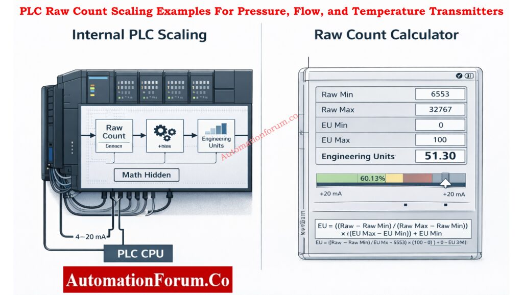
Mathematical Formula Used for PLC Raw Count Scaling
The typical linear scaling equation is used by the PLC Raw Count Calculator:
Engineering Value =
(Raw − RawMin) × (EngMax − EngMin) ÷ (RawMax − RawMin) + EngMin
This formula works for all types of PLCs, Distributed Control Systems (DCS), and industrial controllers.
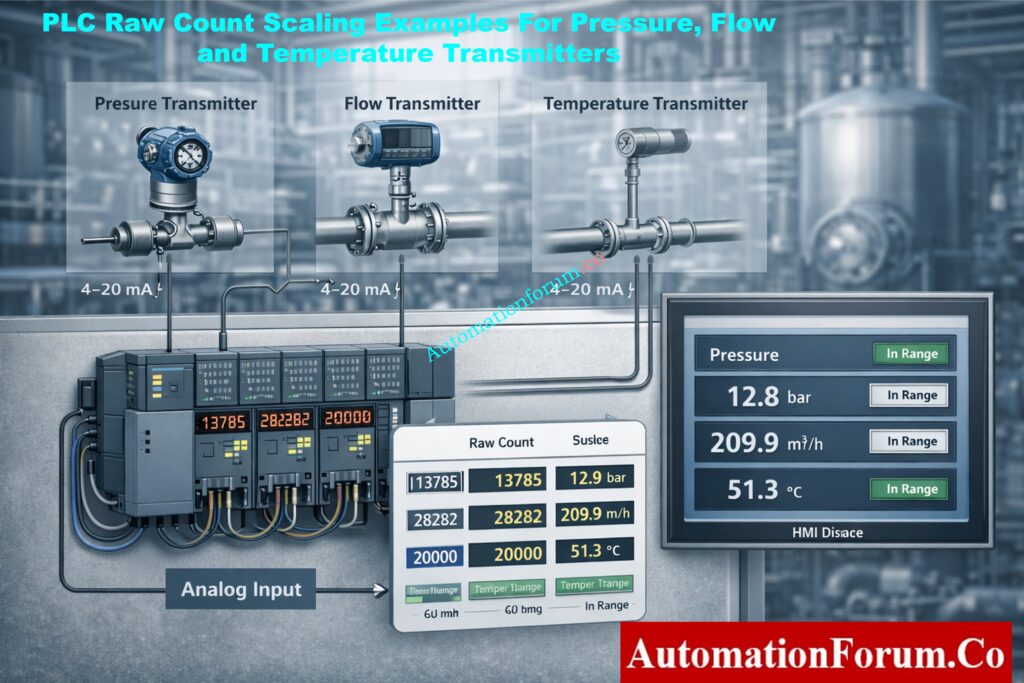
Use-Case Example 1: Pressure Transmitter Scaling in PLC
Pressure Transmitter Configuration (0–10 bar, 4–20 mA)
- Instrument: Pressure Transmitter
- Range: 0–10 bar
- Signal: 4–20 mA
- PLC Platform: Siemens S7-1500
Why 24V DC Is the Standard in PLC Systems (Explained Clearly): Why is 24 Volts Mostly used in Industrial PLC Systems?
PLC Raw Count Values and Engineering Units
- Raw Minimum = 0
- Raw Maximum = 27648
- Engineering Minimum = 0 bar
- Engineering Maximum = 10 bar
Live Operating Condition
- Raw input value read by PLC = 13824
Calculator Result
- Engineering Value = 5.00 bar
- Percentage of range = 50%
- Equivalent current = 12.0 mA
- Signal status = In range
Practical Benefits in Pressure Control Systems
This verification confirms:
- Correct transmitter calibration
- Proper PLC analog module configuration
- Accurate pressure indication on HMI
- Reliable alarm and interlock operation
If this validation isn’t done, a little mistake in the raw range setup could cause the whole process to read the wrong pressure.
Convert DP to Flow Instantly (Process Engineers’ Calculator): Differential Pressure to Flow Calculator – Complete Interactive Tool for Process Engineers
Use-Case Example 2: Flow Transmitter Scaling in PLC
Flow Measurement Using 4-20 mA Signal
- Instrument: Flow Transmitter
- Range: 0–500 m³/h
- Signal: 4–20 mA
- PLC Platform: Allen-Bradley ControlLogix
PLC Raw Count to Flow Rate Conversion
- Raw Minimum = 0
- Raw Maximum = 32767
- Engineering Minimum = 0 m³/h
- Engineering Maximum = 500 m³/h
All PLC Digital Signal Calculators in One Place: Collection of PLC Digital Signal Calculators for Industrial Automation
Live Operating Condition
- Raw input value = 16384
Calculator Result
- Engineering Value ≈ 250 m³/h
- Percentage of range ≈ 50%
- Equivalent current ≈ 12 mA
- Signal status = In range
Impact of Incorrect Scaling on PID Control
Correct flow scaling is critical for:
- PID loop stability
- Accurate totalization
- Batch control accuracy
- Energy and material balance calculations
Even a small difference in scale can generate oscillations or wrong production data.
Convert Thermocouple mV to Temperature Instantly: Thermocouple Voltage ↔ Temperature Calculator
Use-Case Example 3: Temperature Transmitter Scaling in PLC
Temperature Scaling Using Siemens S7-1200 PLC
- Instrument: Temperature Transmitter
- Range: 0–100 °C
- Signal: 4–20 mA
- PLC Platform: Siemens S7-1200
PLC Raw Input Configuration (Typical)
- Raw Minimum = 5530
- Raw Maximum = 27648
Engineering Configuration
- Engineering Minimum = 0 °C
- Engineering Maximum = 100 °C
Live Operating Condition
- Raw input value = 16589
Calculator Result
- Engineering Value ≈ 50 °C
- Percentage of range ≈ 50%
- Equivalent current ≈ 12 mA
- Signal status = In range
Important Note for S7-1200 Users
The bottom part of the raw range is often used for diagnostics in S7-1200 analog modules. Engineers who don’t know how this works often get temperature indications wrong. This is a typical mistake that a raw count calculator can help you avoid.
Calculate Thermowell U-Length Accurately (ASME Tool): Thermowell U-Length Calculator | ASME PTC 19.3 TW-2016 Tool

Analog Fault Simulation Using a PLC Raw Count Calculator
Fault modeling is a big plus for a PLC Raw Count Calculator.
Common Simulated Conditions
- 3.6 mA → Under-range (broken wire, broken sensor)
- 21 mA → Out of range (short circuit, transmitter problem)
Why Fault Simulation Matters
Engineers can check the following via failure simulation:
- PLC diagnostic bits
- Alarm activation limits
- Interlocks for safety
- Messages from the operator on HMI
This may be done without hurting wires or tools, which makes it very handy during FAT and SAT.
Convert RTD Resistance to Temperature Accurately (PT100 / PT1000): RTD Callendar–Van Dusen Calculator | Accurate PT100, PT500, and PT1000 Conversion
PLC Raw Count Calculator in Commissioning and FAT
During commissioning, the calculator helps to:
- Verify IO list accuracy
- Confirm analog loop wiring
- Validate PLC program logic
- Reduce startup time
- Prevent repeated code downloads
When commissioning engineers compare PLC online data with predicted results, they commonly use it as a reference tool.
Size PLC Power Supply Correctly (Avoid PLC Shutdowns): PLC Power Supply Calculator – Complete Guide for Accurate PLC Power Sizing
PLC Raw Count Calculator in Maintenance and Troubleshooting
For maintenance teams, the calculator is invaluable when:
- Process readings appear incorrect
- Operators report abnormal values
- Alarms trigger unexpectedly
- PID loops behave erratically
In many genuine plants, the problem isn’t a broken transmitter; it’s the PLC not scaling correctly. The calculator makes it easy to find this.
Calculate Maximum PSF for Coriolis Flow Meters: Maximum PSF( Pulse Scaling Factor) Calculator for Coriolis Flow Meters
PLC Raw Count Calculator for Training and Skill Development
Analog scaling is hard for students and junior engineers to understand. A calculator for raw counts:
- Makes abstract concepts concrete
- Demonstrates real PLC behavior
- Builds confidence before real plant exposure
- Reduces learning time significantly
Download 82 Must-Have Instrumentation Drawings (Engineer Toolkit): 82 Essential Drawings and Documents for Instrumentation and Control Engineers
Best Practices for Using a PLC Raw Count Calculator
- Always check the module manuals to see what the raw min and raw max are.
- Make sure the settings on the match calculator match the PLC configuration.
- Check the scale before turning on the control loops
- Check how things work when they are too low or too high.
Learn PLC Analog Scaling the Right Way (Raw Count to EU): Scaling Analog Values in Industrial Automation (PLC)
Why Every Automation Engineer Should Use a PLC Raw Count Calculator
PLC internal scaling blocks accomplish important math, but they don’t make independent verification unnecessary. A PLC Raw Count Calculator gives you more information, trust, and validation across platforms than just using internal PLC logic.
This instrument is very important for the whole life cycle of an automated system, from design and commissioning to operation and maintenance. It is used for measuring pressure and flow, controlling temperature, and finding faults.
It is essential for any engineer who works with analog signals to know how to interpret and validate raw count scaling.
Why 4–20 mA Still Dominates Industrial Automation: Why Engineers Still Trust the 4-20 mA Signal in Automation Systems
FAQ on PLC Raw Count and Analog Scaling
What is raw count in PLC?
When an analog input module changes signals like 4–20 mA or 0–10 V into a digital value, that value is called the raw count in PLC. It shows the electrical signal in numbers before it is scaled. Later, raw counts are changed into technical
What are the 4 main parts of PLC?
The four basic pieces of a PLC are the power supply, the CPU (processor), the input modules, and the output modules. The power supply gives the PLC power, the CPU runs logic, the inputs read signals from the field, and the outputs control things like motors and valves.
How to calculate 4-20 mA scaling?
Linear scaling is used to figure out 4–20 mA scaling:
Engineering Value = (Raw − RawMin) × (EngMax − EngMin) ÷ (RawMax − RawMin) + EngMin.
This changes PLC raw counts into useful process quantities like °C, bar, or %.
How to check PLC inputs and outputs?
You can inspect PLC inputs and outputs by checking the I/O status online, forcing signals if you can, and checking the wiring in the field. During commissioning and troubleshooting, input LEDs, output LEDs, multimeter readings, and PLC diagnostics assist make sure everything is working right.
What are the 4 steps of PLC?
There are four steps in how PLC works: Input Scan, Program Execution, Output Update, and Housekeeping. The PLC receives inputs, runs logic, updates outputs, and does internal diagnostics all the while in a scan cycle.
What are 5 output devices?
Motor starters, solenoid valves, control valves, indicator lamps, and relays are five popular PLC output devices. These devices get signals from PLC output modules to control electrical and mechanical processes in industrial automation systems.
Access 100+ Free Instrumentation Calculators (Engineer’s Goldmine): 100+ Online Instrumentation Calculators and Engineering Tools