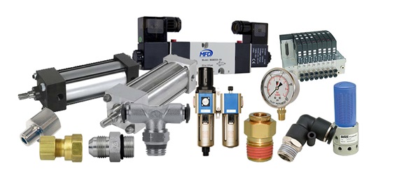
Introduction to some important pneumatic components

Main pneumatic components
All main pneumatic components can be represented by simple pneumatic symbols. Each symbol shows only the function of the component it represents, but not its structure. Pneumatic symbols can be combined to form pneumatic diagrams. A pneumatic diagram describes the relations between each pneumatic component, that is, the design of the system.
Pneumatic components can be divided into two categories:
- Components that produce and transport compressed air.
- Components that consume compressed air.
The production and transportation of compressed air
Examples of components that produce and transport compressed air include compressors and pressure regulating components.
a)Compressor
A compressor can compress air to the required pressures. It can convert the mechanical energy from motors and engines into the potential energy in compressed air (Fig. 2). A single central compressor can supply various pneumatic components with compressed air, which is transported through pipes from the cylinder to the pneumatic components. Compressors can be divided into two classes: reciprocatory and rotary.

b)Pressure regulating component
Pressure regulating components are formed by various components, each of which has its own pneumatic symbol:
- Filter – can remove impurities from compressed air before it is fed to the pneumatic components.
- (ii) Pressure regulator – to stabilize the pressure and regulate the operation of pneumatic components
- (iii) Lubricator – To provide lubrication for pneumatic components

The consumption of compressed air
Examples of components that consume compressed air include execution components (cylinders), directional control valves and assistant valves.
Execution component
Pneumatic execution components provide rectilinear or rotary movement. Examples of pneumatic execution components include cylinder pistons, pneumatic motors, etc. Rectilinear motion is produced by cylinder pistons, while pneumatic motors provide continuous rotations. There are many kinds of cylinders, such as single acting cylinders and double acting cylinders.
Single acting cylinder
A single acting cylinder has only one entrance that allows compressed air to flow through. Therefore, it can only produce thrust in one direction (Fig. 4). The piston rod is propelled in the opposite direction by an internal spring, or by the external force provided by mechanical movement or weight of a load (Fig. 5).

The thrust from the piston rod is greatly lowered because it has to overcome the force from the spring. Therefore, in order to provide the driving force for machines, the diameter of the cylinder should be increased. In order to match the length of the spring, the length of the cylinder should also be increased, thus limiting the length of the path. Single acting cylinders are used in stamping, printing, moving materials, etc.
Double acting cylinder
In a double acting cylinder, air pressure is applied alternately to the relative surface of the piston, producing a propelling force and a retracting force (Fig. 6). As the effective area of the piston is small, the thrust produced during retraction is relatively weak. The impeccable tubes of double acting cylinders are usually made of steel. The working surfaces are also polished and coated with chromium to reduce friction

Safety measures when using pneumatic control systems
(a) Compressed air can cause serious damage to the human body if they enter the body through ducts like the oral cavity or ears.
(b) Never spray compressed air onto anyone.
(c) Under high temperature, compressed air can pass through human skin.
(d) Compressed air released from the exhaust contains particles and oil droplets, which can cause damage to eyes.
(e) Even though the pressure of compressed air in pipes and reservoirs is relatively low, when the container loses its entirety, fierce explosions may still occur.
(f) Before switching on a compressed air supply unit, one should thoroughly inspect the whole circuit to see if there are any loose parts, abnormal pressure or damaged pipes.
(g) A loose pipe may shake violently due to the high pressure built up inside it. Therefore, each time before the system pressure is increased, thorough inspection of the entire circuit is required to prevent accidents.
(h) As the force produced by pneumatic cylinders is relatively large, and the action is usually very fast, you may suffer serious injuries if you get hit by a cylinder.
(i) Switches should be installed on the compressed air supply unit to allow easy and speedy control of air flow.
(j) In case of a leakage, the compressed air supply unit should be turned off immediately.
(k) The compressed air supply unit must be turned off before changes can be made to the system.
(l) Stay clear of the moving parts of the system. Never try to move the driving parts in the mechanical operation valve with your hand.
Also read


