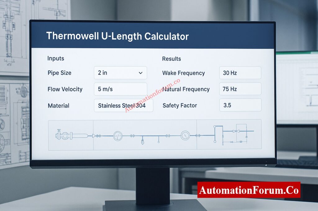
- Use Our Free Thermowell U-Length Calculator
- What is a Thermowell and Why It Matters
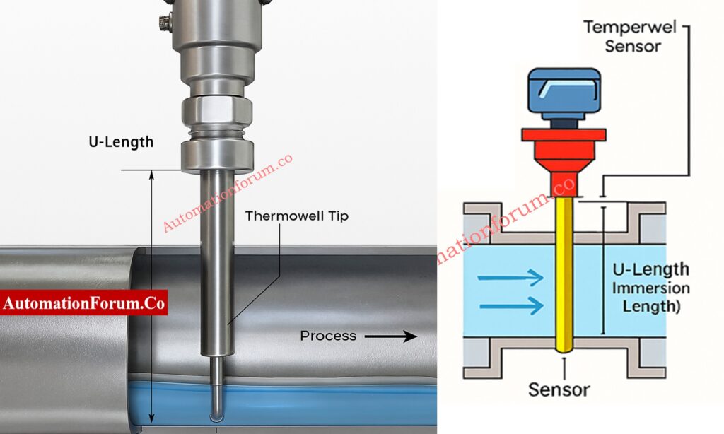
- What Is Thermowell U-Length (Immersion Length)?
- How the Thermowell Calculator Works
- Calculated Output Results and Their Meaning
- Engineering Design Approach in the Calculator
- Common Materials and Their Applications
- Step-by-Step Thermowell Selection for EPC Design Engineers
- Important Design Notes and Limitations
- Features of the Online Thermowell U-Length Calculator
- Example Calculation (Sample Data)
- Thermowell U-Length FAQs
In every EPC (Engineering, Procurement, and Construction) project, designing thermowells for process instrumentation is an important job. If you choose the wrong length or material for your thermowell, it could give you wrong temperature readings, cause your sensor to malfunction, or even cause your system to vibrate in a way that could be very bad.
Automationforum.co has a robust Thermowell U-Length Calculator that makes it easier to design preliminary thermowells. It is based on simple rules that follow ASME PTC 19.3 TW-2016.
This tool helps engineers figure out the best immersion length (U-length), look at stresses caused by flow, and make sure the thermowell is dynamically stable so that temperature readings are safe and accurate.
Use Our Free Thermowell U-Length Calculator
This free thermowell U-length calculator will help you find the right immersion length, wake frequency, and vibration safety for measuring temperature in process piping systems.
Thermowell U-Length Calculator
Calculate optimal immersion length based on ASME PTC 19.3 standards
Here you can refer more 200+ Online Instrumentation Calculators Collections
What is a Thermowell and Why It Matters
A thermowell is a protective cover that goes around temperature sensors (such RTDs or thermocouples) in a process line or vessel to keep them safe from harsh circumstances like high pressure, fast flow, and corrosion.
It lets you change sensors without stopping the operation and makes sure that the temperature is measured correctly while keeping the system's integrity.
The U-length, or immersion length, tells you how far the sensor goes into the process media. Choosing the right U-length makes sure that temperature readings are accurate and that vibrations caused by flow are kept to a minimum.
What Is Thermowell U-Length (Immersion Length)?
Engineers who work on EPC designs have to find a balance between process precision, mechanical safety, and material choice. The Thermowell U-Length Calculator does quick and smart math to help with:
- Finding the best U-length for the best sensor performance
- Checking the natural frequency and wake frequency to stop resonance
- Finding the Reynolds number to look at how the flow behaves
- Giving safety factors to make sure machines work reliably
- Supporting Excel reports that can be exported for documentation and approval
Before doing extensive ASME PTC 19.3 TW-2016 thermowell stress and vibration calculations, this tool checks the design.
Get 82 Must-Have I&C Documents: 82 Essential Drawings and Documents for Instrumentation and Control Engineers
How the Thermowell Calculator Works
Key Input Parameters and Their Definitions
Here are the primary parameters that this calculator uses, along with their engineering meanings and importance:
| Parameter | Definition / Description |
| Pipe Nominal Size (mm) | The nominal diameter of the process pipeline where the thermowell is put in. It figures out how much space is left for input. 50, 80, 100, and 150 mm are common diameters. |
| Pipe Schedule | Pipe Schedule Shows how thick the pipe's walls are (for example, STD, XS, XXS). It changes the internal diameter, which affects how easy it is to immerse. |
| Flow Velocity (m/s) | This is the speed at which the process fluid moves through the thermowell in a straight line. When the speed is high, the risk of vibration and wake frequency goes up. |
| Fluid Density (kg/m³) | The amount of mass in a certain amount of process fluid. It changes the Reynolds number and the way things vibrate. |
| Fluid Viscosity (Pa·s) | The fluid's resistance to flow on the inside. It changes the way the boundary layer forms and the stresses caused by flow. |
| Tip Diameter (mm) | The smallest diameter at the end of the thermowell where it senses. A smaller tip makes the response time faster, but it might make the mechanical strength weaker. |
| Root Diameter (mm) | The diameter of the base where the thermowell connects to the process. For structural integrity, it must always be bigger than the tip diameter. |
| Material Selection | Finds out how strong, resistant to corrosion, and thermally stable a thermowell is. Common materials are SS316, SS304, Inconel 600, and Monel 400. |
| Sensor Type (RTD / TC) | Sensor Type (RTD / TC) tells you what kind of temperature sensor is within the thermowell. For stability, RTDs need to be immersed deeper, although thermocouples respond more quickly. |
| Process Temperature (°C) | Process Temperature (°C) The temperature of the fluid in the process. It affects the choice of materials and the estimates of stress. |
Discover Why Thermowells Use 45° Angle: Why Install Thermowells at a 45° Angle? Engineering Logic Explained
Calculated Output Results and Their Meaning

The calculator gives engineers a full range of outputs that help them understand how thermowells behave in real-world situations.
1. Recommended U-Length
The advised length of immersion that will give you an accurate temperature reading without too much vibration. Usually between 35% and 40% of the pipe's inner diameter, or less if there are limits on vibration.
2. Minimum Immersion
The minimum depth needed to make sure that the sensor's tip is fully exposed to the process fluid, which makes it more accurate. Usually, this is the length of the sensor plus 25 mm.
3. Maximum Allowable Length
The longest immersion time that keeps the mechanical integrity and avoids resonance circumstances based on the stiffness of the material and the flow forces.
4. Pipe Inner Diameter
Calculated based on the pipe schedule and nominal size you chose. It changes how much the thermowell can stick out into the flow.
5. Reynolds Number (Re)
A number without dimensions that describes the flow regime:
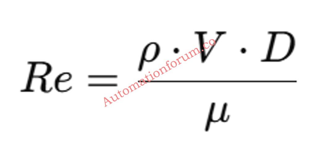
where ρ is density, V is velocity, D is diameter, and μ is viscosity.
If Re is less than 2000, the flow is laminar; if Re is more than 4000, the flow is turbulent.
6. Wake Frequency
The number of vortices that form behind the thermowell because to the flow of fluid. Too many wakes close to the thermowell's inherent frequency can produce resonance and fatigue failure.
7. Natural Frequency
The natural frequency at which the thermowell vibrates. According to ASME PTC 19.3 TW-2016, safe designs keep the natural and wake frequencies at least 2.2 times apart.
8. Response Time
The sensor's response time to a temperature change is affected by the thickness, material, and flow conditions of the thermowell.
9. Safety Factor
Compares the design limits that are allowed with the design limits that are actually used to show mechanical reliability. In process applications, a safety factor of more than 1.5 to 2.0 is usually better.
Understand Thermowell Insertion and U-Length: Thermowell Insertion and Immersion Length
Engineering Design Approach in the Calculator
This thermowell calculator is based on a simple physics model that is in compliance with industry standards. The basic logic structure employed is as follows:
Pipe Inner Diameter Estimation:
Using internal lookup values, we figured it out based on the nominal size and timetable.
Flow Parameter Calculation:
- The Reynolds number is based on the flow speed, density, and viscosity.
- The flow regime helps figure out the wake frequency.
Mechanical Analysis:
- The thermowell is treated as a cantilever beam that is pushed and pulled by moving forces.
- The tip and root sizes affect the moment of inertia and stiffness.
- The calculator uses the modulus and geometry of the material to figure out the natural frequency.
U-Length Determination:
The tool automatically chooses the lowest value from the pipe limit, vibration limit, and mechanical limit to make sure it is safe.
Thermal Response Estimation:
This uses the thermal mass and heat transfer coefficients to guess how long it will take the sensor to respond.
Safety Factor Computation:
The ratio of the maximum vibration limit to the actual U-length gives a quick reliability index.
Refer the below link to Master Thermowell Selection for EPC Projects:
Common Materials and Their Applications
| Material | Density (kg/m³) | Modulus of Elasticity (Pa) | Allowable Stress (MPa) | Application Notes |
| SS316 | 8000 | 1.93×10¹¹ | 138 | Excellent corrosion resistance; widely used in general process industries. |
| SS304 | 8000 | 1.93×10¹¹ | 138 | Cost-effective for mild environments. |
| Inconel 600 | 8470 | 2.14×10¹¹ | 207 | High-temperature strength and oxidation resistance. |
| Monel 400 | 8800 | 1.79×10¹¹ | 172 | Ideal for marine and caustic service. |
Choose Correct Sensor Wet Part Materials: How to Select the Right Wet Part Materials of Sensors in Process Industries
Step-by-Step Thermowell Selection for EPC Design Engineers
The Thermowell U-Length Calculator is a useful tool for EPC design engineers while they are doing the fundamental and thorough engineering for instrumentation design.
It supports:
- Preliminary sizing and checking before buying
- Checking vendor papers and datasheets
- Technical examination of bids from thermowell providers
- Combining P&ID and 3D modeling data to plan instrument insertion
Excel output that may be exported makes it easier to examine and approve project documents and QA/QC submissions.
Decode Temperature Transmitter Datasheets Easily: How to Read a Datasheet of a Temperature Transmitter ?
Important Design Notes and Limitations
- The calculator employs basic vibration and heat models that are good for early design work.
- A complete finite element or ASME PTC 19.3 TW-2016 study must be done for important applications (high speed, long U-length, or high temperature).
- Based on the pressure in the system, make sure that the process connection strength is good enough (flanged, threaded, or welded).
- Before finishing the U-length, check the clearance for insertion depth in valves, elbows, or vessels.
Always get final design approval from a thermowell expert or manufacturer.
Reason Behind RTDs Downstream of Orifice: Why RTD Temperature Sensors are Installed Downstream of Orifice Plates?
Features of the Online Thermowell U-Length Calculator
- What the Online Thermowell U-Length Calculator Can Do
- Web interface that works on both desktop and mobile devices
- Instant Results: dynamic calculation in real time
- Export to Excel Function: Makes a structured report with all the input and output parameters
- Print Option: For keeping records of the project
Error Validation: Ensures logical and numerical accuracy
Built-in Material Database: For automatic property selection
Follow This Thermocouple Commissioning Checklist: Thermocouple Commissioning Checklist
Example Calculation (Sample Data)
For a 4-inch (100 mm) pipe with a regular schedule, a flow speed of 2 m/s, a water density of 1000 kg/m³, and an SS316 thermowell:
- Recommended U-Length: ~37 mm
- Minimum Immersion: 75 mm
- Max Allowable Length: 53 mm
- Reynolds Number: ~16,000
- Wake Frequency: 50 Hz
- Natural Frequency: 120 Hz
- Safety Factor: 1.9
This makes sure the design is within the limitations for vibration and that the process temperature is measured correctly.
The Thermowell U-Length Calculator from automationforum.co is a dependable design tool for instrumentation and EPC professionals to check the size and performance of thermowells.
It combines basic physics, material attributes, and process dynamics to make it easy to choose the right thermowell quickly and accurately, which saves time during engineering, procurement, and commissioning.
This calculator makes sure that your thermowell design is safe, efficient, and meets the standards set by ASME PTC 19.3 TW-2016, whether you're planning for an oil refinery, a chemical plant, or a power production unit.
Essential RTD Commissioning Checklist for Engineers: RTD Commissioning Checklist
Thermowell U-Length FAQs
What is thermowell U-length?
The immersion length, or Thermowell U-length, is the part of the thermowell that goes from the process connection into the fluid stream. The unsupported length is what tells the sensor how deep it can measure temperature in the process.
What is the U-length thermowell?
A U-length thermowell is just a thermowell that is defined by how deep it is immersed. The right U-length makes sure that the temperature sensor is suitably exposed to the process fluid for accurate measurement while also keeping the mechanical stability.
What is U-length?
The U-length (or insertion length) is the distance from the bottom of the thermowell mounting connector to the top of the well. It tells you how much of the thermowell is inside the process media.
How to calculate thermowell length?
To get an accurate temperature reading, the thermowell length is depending on how deep it needs to be (typically 1/3 to 1/2 of the pipe's inner diameter).
- Extra stand-out for insulation or lagging (T-length).
- Using ASME PTC 19.3 TW-2016 to check vibration and strength by calculating wake frequency and natural frequency.
- Final length = U (immersion) + T (lagging or stand-out) + connection allowance.
What is WFC calculation?
WFC is short for Wake Frequency Calculation. It checks the vibration that happens when fluid flows around the thermowell. The computation makes sure that the thermowell's inherent frequency is substantially greater than the wake (vortex shedding) frequency. This is to prevent resonance and fatigue failure.
What is the standard for thermowell?
The basic design reference is ASME PTC 19.3 TW-2016. This document has guidelines for figuring out thermowell stresses, wake frequency, and natural frequency to make sure that the machine is safe under flow and pressure conditions.
How to select a thermowell?
To choose the right thermowell:
- Set the process conditions, such as pressure, temperature, speed, and kind of fluid.
- Pick a material that can handle high temperatures and corrosion.
- Choose a shape: straight, tapered, or stepped.
- Find the right U-length for proper immersion.
Verify mechanical and vibration safety using ASME PTC 19.3 TW-2016.
Thermocouple Troubleshooting Checklist You Need: Check List: How to Troubleshoot a Thermocouple?
, wake frequency, and vibration safety using ASME PTC 19.3 TW-2016. Ideal for EPC instrumentation engineers.)