- Why PLC Permissive Logic is Critical in Process Plants
- What is PLC Permissive Logic?
- Permissive vs Interlock – Key Differences
- Typical Architecture of a Permissive System
- Core Categories of Permissives
- Step-by-Step PLC Permissive Troubleshooting Workflow
- Step 1: Confirm the Start Is Blocked by Permissive Logic
- Step 2: Check the Final Permissive Output Tag
- Step 3: Analyze the Permissive Ladder Logic Rung-by-Rung
- Step 4: Verify Design Intent Using Cause & Effect Diagram
- Step 5: Use AOI FIRST-OUT Diagnostics
- Step 6: Verify Field Instrument Health
- Step 7: Inspect PLC I/O Modules and Wiring
- Step 8: Review HMI Permissive Faceplate
- Step 9: Clear Faults and Retest the Start Sequence
- Troubleshooting Scenarios for PLC Permissive (Real-World Examples)
- Recommended PLC Tagging and Naming Conventions for Permissives
- Documentation and Post-Incident Reporting for Permissive Failures
- Advanced Trending, Analytics and Preventive Maintenance Strategy
- Advanced Trending, Analytics, and Preventive Maintenance Strategy
- Root Cause Analysis (RCA) Flow for PLC Permissive Failures
- Regulatory and Safety Compliance Considerations for PLC Permissives
- FAQ on PLC Permissive Logic Troubleshooting
Why PLC Permissive Logic is Critical in Process Plants
In today’s process industries, like oil and gas, chemicals, power generation, water treatment, and pharmaceuticals, PLC permissive logic is the safety net that keeps people, equipment, and production goals safe. A pump, compressor, or fan may look like it’s ready to go, but the PLC won’t let it start unless all of the predefined permissive criteria are met.
Instrument engineers deal with permissive logic problems every day. A single broken pressure transmitter, an MCC feedback that isn’t lined up right, or an AOI that isn’t set up correctly can bring down a whole unit. This paper is meant to help engineers understand, fix, and explain PLC permissive logic in a systematic, real-world way using ladder logic, the Cause & Effect philosophy, AOI diagnostics, and HMI interpretation.
This guide is intentionally written for:
- Instrumentation & control engineers
- PLC commissioning engineers
- Maintenance technicians
- Automation trainers and technical bloggers
What is PLC Permissive Logic?
Before an action may happen, PLC permissive logic says that a series of logical conditions must be TRUE. Most of the time, the action is to start a pump, open a valve, or turn on a drive.
PLC permissive logic is a set of logical criteria that must all be TRUE before a PLC will let something happen, such starting a pump, turning on a motor, or opening a critical valve.
Permissives are purposely cautious. The PLC stops the start command if even one permissible condition fails. This design philosophy puts safety, protecting equipment, and keeping processes stable ahead of making things available right away.
Some common examples of permissive situations are:
- Reset the emergency stop
- MCC or beginning comment that is good
- Good enough suction pressure
- Level of vibration that is okay
- Drive is ready
PLC Permissive Circuits Finally Explained: Permissive circuits in PLC
Permissive vs Interlock – Key Differences
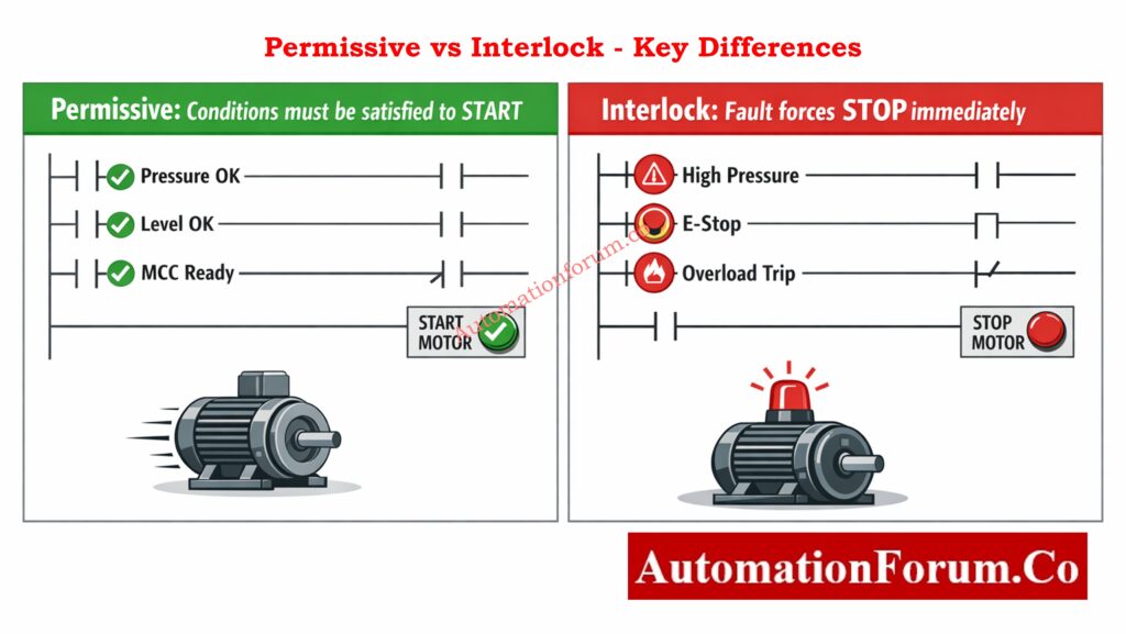
| Aspect | Permissive | Interlock |
| Purpose | Allows an action | Prevents an action |
| Logic nature | Positive logic (OK = 1) | Negative logic (Trip = 1) |
| Typical use | Start conditions | Emergency protection |
| Example | Suction pressure OK | High vibration trip |
When you’re trying to figure out what’s wrong with a machine, it’s important to know the difference between permissives and interlocks. Permissives tell you why a machine won’t start, while interlocks tell you why it stopped.
Logic Gates Simulator Engineers Love: Logic Gates Explained with Truth Table Animated Simulator (PLC & Instrumentation Guide)
Typical Architecture of a Permissive System
Core Categories of Permissives
1. Electrical Permissives
Electrical permissives make sure that electricity and protection systems are working properly:
- MCC healthy feedback
- Emergency Stop reset
- Overload reset
- Ground fault cleared
A single missing electrical feedback can block a start, even if all process conditions are perfect.
Gas Turbine Interlocks Test Yourself: Gas Turbine Start Interlocks Quiz – 25 Advanced MCQs for Engineers
2. Process & Pressure Permissives
Process permissives rely heavily on instrumentation:
- Suction pressure within limits
- Discharge pressure not high
- Flow confirmation
- Temperature within safe range
These are often implemented using 2-out-of-3 (2oo3) voting logic to improve reliability.
3. Mechanical Permissives
Mechanical conditions protect equipment integrity:
- Seal pressure OK
- Vibration normal
- Lube oil pressure OK
- Bearing temperature normal
4. Drive & Control Permissives
Drive permissives ensure control readiness:
- VFD ready
- Drive fault-free
- Speed reference valid
5. Operator & Maintenance Permissives
These include:
- Local/Remote selector
- Maintenance mode
- Bypass key enable
It is important to constantly explicitly mark and log maintenance bypasses on HMI.
Alarm Trip Setpoints You Must-Know: Alarm & Trip Setpoint List in Instrumentation Engineering: The Most Critical Document for Plant Safety
Step-by-Step PLC Permissive Troubleshooting Workflow
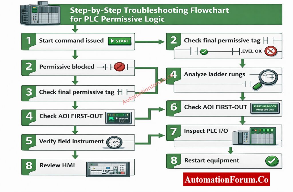
Step 1: Confirm the Start Is Blocked by Permissive Logic
Check if the inability to start is really because of permissives before opening PLC logic or checking instruments.
Some common signs are:
- Operator issues a start command
- No motor rotation or drive start
- HMI message such as “Start Blocked – Check Permissives”
At this point, don’t make any assumptions. Make sure that permissive logic is to blame and that the problem is not caused by a power loss, a breaker trip, or a mechanical lock-out.
PLC Panel Inspection Mistakes Engineers Make: Running Inspection Checklist of PLC Components in Control Panels
Step 2: Check the Final Permissive Output Tag
Find the last permissible output tag in the PLC program. It will usually be called something like:
- Pump_Perm_OK
- Motor_Start_Perm
- Permissive_OK
Interpret the result carefully:
- If the final permissive is TRUE, the problem lies downstream (starter, wiring, MCC, or motor).
- If the final permissive is FALSE, continue with permissive troubleshooting.
This one check right away narrows down the troubleshooting area and stops work that isn’t needed.
Triconex PLC Differences Engineers Ignore: Difference Between Triconex PLC and Other PLCs: A Complete Guide
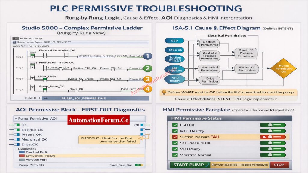
Step 3: Analyze the Permissive Ladder Logic Rung-by-Rung
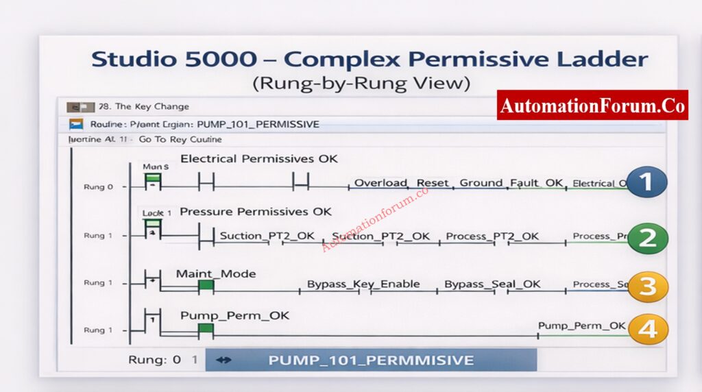
A permissive ladder is usually set up with each rung being a logical series of conditions.
Permissive logic is normally divided into logical rungs, each representing a group of conditions. Analyze them sequentially.
Electrical Permissive Rung
This rung typically verifies:
- MCC health or contactor feedback
- Reset of the emergency stop circuit
- Reset the overload relay
- Ground fault fixed
If any signal is FALSE, check to see if the problem is real or if it is caused by wiring problems, broken auxiliary contacts, or PLC input module problems.
ControlLogix Security Flaw Engineers Must-Know: Critical Flaw in Rockwell ControlLogix CVE-2024-6242 – Trusted Slot Bypass Vulnerability
Process and Pressure Permissive Rung
This rung evaluates process safety conditions such as:
- Suction pressure within limits
- Discharge pressure below high limit
- Flow present
Many plants use 2-out-of-3 voting logic for critical pressures. Always evaluate the voting result, not just individual transmitter readings. A single failed transmitter may not block the start, but two failed transmitters will.
Always troubleshoot from left to right and top to bottom, exactly how the PLC scans logic. When a final output is false, trace each upstream rung to find the first rung where the logic evaluates to false.
Put the ladder into logic forcing mode and toggle the suspected inputs one by one (for example, force the suction pressure OK tag) and observe the effect on FIRST‑OUT. But remember: never force a tag without proper safety permissions and clear communication with operations.
Maintenance and Bypass Rung
This rung checks:
- Maintenance mode status
- Bypass key enable
- Temporary commissioning overrides
People often get confused when they forget or use an unauthorized shortcut. Before assuming a process error, always check the status of the bypass.
Motor Starter Interlocks Engineers Misunderstand: PLC Program for Motor Starter with Low-Level Switch Interlock
Step 4: Verify Design Intent Using Cause & Effect Diagram
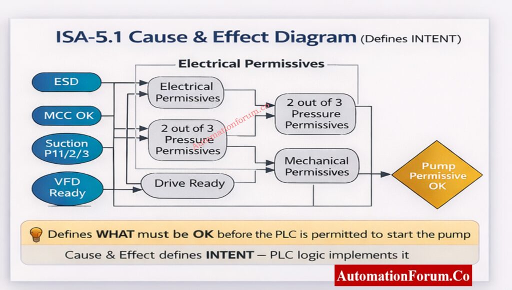
The Cause & Effect (C&E) diagram, as per ISA-5.1, defines WHAT must be OK before the PLC is allowed to act. It does not describe code it describes intent.
Why Cause & Effect Important
- Serves as the contractual logic reference between process engineers and control engineers
- Links process safety to control logic and HMI behavior
- Ensures consistency across PLC, DCS, and emergency systems
Mapping C&E to PLC Logic
| Cause & Effect Element | PLC Implementation | Additional Checks |
| Electrical permissives | Ladder rung / AOI input | Verify I/O channel health |
| 2oo3 pressure logic | Voting logic block | Validate sensor calibration & drift |
| Mechanical permissives | AOI input | Check sensor mounting & mechanical condition |
| Pump permissive OK | Final output coil | Confirm interlock with motor starter |
Cause & Effect (C&E) diagrams define what conditions must be satisfied before a start is permitted. They represent the safety and operational intent of the system.
During troubleshooting:
- Confirm that every permissive in the ladder exists in the C&E diagram
- Check that the voting rationale satisfies the C&E definition.
- Find any undocumented permissions that were added during changes.
If there is a difference between C&E and PLC logic, it should be seen as a big design problem.
Always keep the C&E and ladder logic in sync. Use code comments or a mapping document that links each C&E bubble to a PLC tag and AOI parameter so field technicians can quickly find the implementation.
NO NC Contact Mistakes Explained: Understanding NO vs NC Contacts is key for Logic Writing in PLC Programming
Step 5: Use AOI FIRST-OUT Diagnostics
What is an AOI?
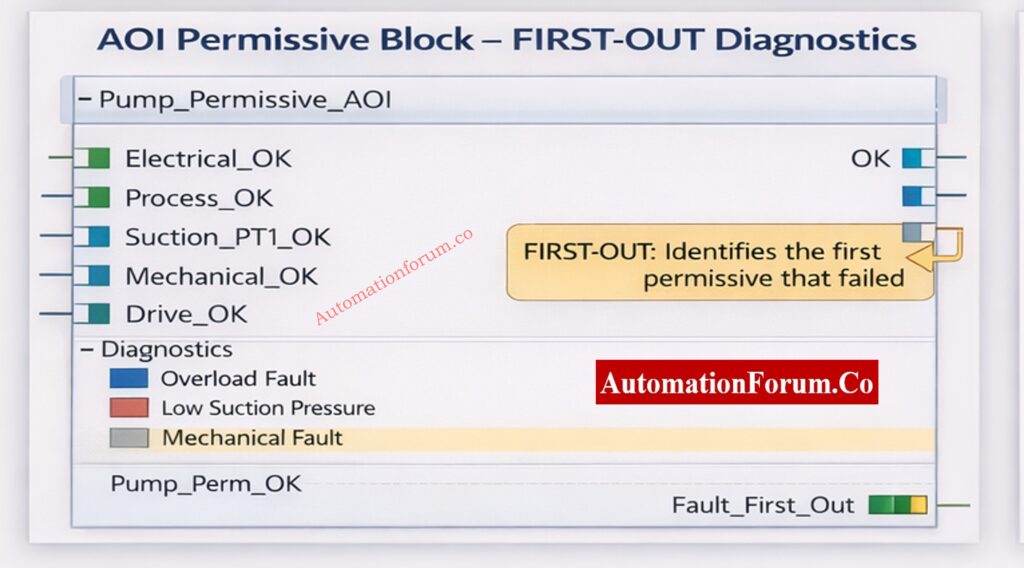
An Add-On Instruction (AOI) is a reusable logic block that standardizes permissive logic across equipment. AOIs can contain inputs, outputs, and internal tags which makes them ideal for consistent FIRST‑OUT behavior.
FIRST-OUT Logic Explained
FIRST-OUT logic captures the first permissive that fails, even if multiple permissives fail later. The AOI sets a Fault_First_Out tag and often a code or priority bitset that the HMI can interpret.
Benefits:
- Faster troubleshooting by pointing to the root cause
- Easier operator guidance because HMI can show the likely cause
- Better trending and reliability metrics because the first fault is logged
Implementation notes
- Use timestamped fault registers in AOIs to capture when the first failure occurred.
- Include a ‘clear’ or ‘acknowledge’ mechanism that does not erase historical logs- use a separate event log for permanent records.
Modern PLC systems use Add-On Instructions (AOIs) to standardize permissive logic. A well-designed AOI includes FIRST-OUT diagnostics, which record the first permissive that failed.
- Read the FIRST-OUT diagnostic tag
- Identify the first permissive that transitioned to FALSE
- Focus troubleshooting on this permissive only
FIRST-OUT logic prevents engineers from chasing secondary or consequential faults.
Solenoid Valve Failures Engineers Miss: Step-by-Step Procedure to Troubleshooting Solenoid Valves in PLC Digital Output Loops
Step 6: Verify Field Instrument Health
Once the failed permissive is identified, verify the associated field instrument:
- Check live process value on HMI or trend
- Review transmitter diagnostics (HART / fieldbus)
- Cross-check with a handheld calibrator
- Inspect impulse lines, sensing points, and mechanical connections
Never clear a permissive logically without confirming the physical process condition.
Why 24V PLC Power Wins: Why is 24 Volts Mostly used in Industrial PLC Systems?
Step 7: Inspect PLC I/O Modules and Wiring
If the field instrument is confirmed healthy:
- Check PLC I/O module LEDs and diagnostics
- Review channel error flags
- Inspect marshalling cabinets and termination points
- Verify cable shielding and grounding
Intermittent wiring faults often manifest as sporadic permissive failures.
PLC Output Faults Stop Plants: Step-by-Step Procedure for Troubleshooting PLC Digital Outputs
Step 8: Review HMI Permissive Faceplate
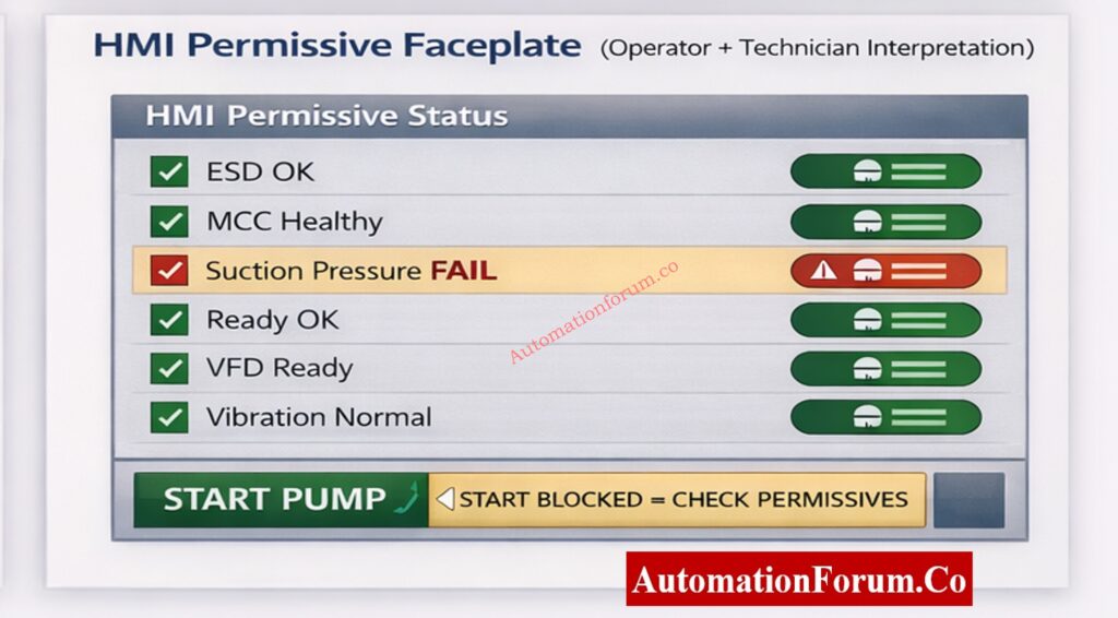
The HMI should clearly display:
- Individual permissive statuses
- FIRST-OUT condition
- Clear reason for start blockage
If the HMI only shows a generic alarm, the issue may be poor interface design rather than PLC logic.
The HMI is the bridge between PLC logic and human decision-making.
Best Practices for HMI Permissives
- Clear OK / FAIL indication with accessible color contrast for color-blind users
- Highlight FIRST-OUT condition with a distinctive icon and link to a diagnostic page
- Avoid ambiguous alarms – use plain language and recommended action
Example Interpretation
If Suction Pressure FAIL is highlighted:
- Operator sees start blocked and FIRST-OUT pointing to Suction Pressure
- Technician checks pressure trend and HART diagnostics
- Instrument engineer verifies transmitter health with a handheld calibrator and checks the impulse line for blockages
- Once fixed, AOI/PLC will clear FIRST-OUT and HMI updates to green
Step 9: Clear Faults and Retest the Start Sequence
After correcting the root cause:
- Reset alarms and permissive faults
- Remove all bypasses and forces
- Re-issue the start command
- Observe permissive status throughout startup
Always verify at least one successful start before closing the job.
2oo4 Voting Logic Explained Clearly: Designing 2 out of 4 Voting Logic in Control Systems: A Step-by-Step PLC Ladder Diagram Tutorial with Video
Troubleshooting Scenarios for PLC Permissive (Real-World Examples)
Below are common real-world scenarios with quick diagnosis steps and recommended fixes. Use these as a quick reference during field troubleshooting.
Scenario A – Suction Pressure Permissive Failure
Symptoms: HMI shows Pump_Perm_OK = FALSE and FIRST-OUT indicates Suction_Pressure_FAIL.
Immediate checks: Read live suction pressure trend; inspect the impulse line and filter/strainer; check the transmitter healthy bit.
Likely root causes & fixes:
- Blocked suction strainer – clean or replace strainer.
- Transmitter calibration drift – calibrate or replace transmitter.
- Impulse line air trapped – bleed the impulse line.
Verification: Restore signal, confirm reading on HMI, clear FIRST-OUT, reattempt start.
Scenario B – MCC Healthy Feedback FALSE
Symptoms: MCC_Healthy = FALSE even though motor starter appears energized.
Immediate checks: Inspect motor starter auxiliary contact, check MCC bus voltages, and confirm breaker position.
Likely root causes & fixes:
- Auxiliary contact welded or stuck – replace or repair contactor.
- Faulty PLC digital input – test and replace I/O channel.
- MCC communication fault (if feedback over fieldbus) – check gateway and bus.
Scenario C – Drive ‘Ready’ Flapping (Intermittent)
Symptoms: Drive shows ‘Ready’ flapping between TRUE and FALSE causing permissive to toggle.
Immediate checks: Examine drive event log for overtemperature, input supply variations, or communication timeouts.
Likely root causes & fixes:
- Drive thermal derating due to cooling issue – clean filters and verify cooling fans.
- Intermittent communication (EtherNet/IP) – inspect switch ports and cabling.
- Supply voltage sags – investigate upstream power quality.
Recommended PLC Tagging and Naming Conventions for Permissives
Good naming makes it easier to find things in PLC projects and helps you compare diagrams and documents.
- PUMP101_PERM_OK – final permissive
- PUMP101_SUCT_PT_HART_STAT – HART status bit
- PUMP101_FAULT_FIRST_OUT – AOI FIRST-OUT code
- PUMP101_MCC_AUX_FB – MCC auxiliary feedback
Good naming makes it easier to find things in PLC projects and helps you compare diagrams and documents.
Permissive Logic Every Engineer Must-Know: Understanding Permissive Logic and Trip Interlocks in Industrial Systems
Documentation and Post-Incident Reporting for Permissive Failures
After fixing a permissive-related outage, provide a concise report about what happened that includes:
- Time of failure and recovery
- Tag for FIRST-OUT and the root cause
- Steps done to correct things and the outcomes of those steps
- Any temporary bypasses that were used and who gave them permission
- Suggested ways to stop problems before they happen (such replacing sensors or making HMI better)
This report helps with ongoing progress and cuts down on recurrent failures.
2oo3 Voting Logic Explained Clearly: Designing 2 out of 3 Voting Logic in Control Systems: A Step-by-Step PLC Ladder Diagram Tutorial with Video
Advanced Trending, Analytics and Preventive Maintenance Strategy
Use historian data and rudimentary analytics to turn events that are allowed into reliability improvements that you can act on. Make the following trends and dashboards:
- First-Out Frequency Chart: This chart shows how many FIRST-OUT events happen per tag each month. It helps find people who do it more than once.
- Time-to-Fix Trend: The time between the FIRST-OUT timestamp and the restoration. This shows MTTR for permissive issues.
- Voting Logic Failures: Keep an eye on cases where voting outputs stopped a start. This can assist find problems with sensor dependability.
NOTE: Set up historian exports for the AOI FAULT_FIRST_OUT tag, the final permissive tag, and the critical transmitter health bits. Make a simple dashboard that lets you filter by equipment, shift, and root cause.
Business benefit: Trending shows long-term problems (such bad sensor installation, electrical noise, or repeated use of a bypass) that single incident reports don’t catch.
Advanced Trending, Analytics, and Preventive Maintenance Strategy
A well-planned preventive maintenance (PM) program cuts down on permissive failures by a huge amount. Important PM steps:
- Calibration timetable for sensors: every 3 to 6 months for critical transmitters (suction/discharge pressure, flow), depending on how bad the process is.
- I/O integrity checks: Every three months, verify the termination blocks, torques, and grounding.
- Check your drive regularly: look over your event record once a month and check your cooling system once a quarter.
- HMI and AOI audit: Once a year, check that the AOI diagnostics and HMI faceplates show the most up-to-date logic and C&E.
Keep track of PM work in the CMMS and link work orders to FIRST-OUT events that can check how well PM works.
Boiler Burner Faults Test Engineers: Advanced Boiler Burner Control System Troubleshooting Quiz
Root Cause Analysis (RCA) Flow for PLC Permissive Failures
If a permissible failure stops production, do a rapid RCA by following these steps:
- Set the time, tools, and FIRST-OUT tag for the event.
- Get proof, such AOI logs, historian trends, and I/O diagnostics.
- Find the immediate cause, like a broken transmitter, bad wiring, or a driving event.
- Find the main problem, which could be a poor installation, not enough PM, or something wrong with the surroundings.
- adjust the sensor, update the PM, or adjust the AOI as a possible solution.
- After the adjustment, keep a watch on the FIRST-OUT frequency to check if it worked.
Include the RCA summary in the report after the occurrence, and make sure someone is in charge of fixing things.
Regulatory and Safety Compliance Considerations for PLC Permissives
Permissive logic commonly works with safety systems like ESD and SIS. Remember these rules:
- Don’t ever put safety-critical permissives in non-safety PLC code alone; use SIS as necessary.
- For audits, keep track of the connections between C&E, PLC logic, and safety instrumented functions (SIF).
Following ISA standards and local laws lowers the chance of legal problems and accidents.
Adding sophisticated trending, preventative maintenance, and a systematic RCA process to your permissive troubleshooting technique will make your plant stronger. This article’s steps help instrumentation engineers find and fix permissive-based start failures while keeping safety and compliance in mind.
These minor behaviors, like following the checklist, following safety rules, and writing down anything you notice, can help you work faster and give operators and engineers more confidence.
PLC I O Failures You Must-Prevent: Proactive Maintenance Strategies for PLC I/O Modules: Reduce Downtime & Improve Reliability
FAQ on PLC Permissive Logic Troubleshooting
What is a PLC permissive?
A PLC permissive is a logical condition that must be TRUE for a PLC to let something happen, such turning on a pump or motor. Before starting up, it makes sure that the electrical, process, and mechanical conditions are all safe.
How to troubleshoot PLC problems?
When you debug a PLC, you check the power, I/O status, logic conditions, and communication health. When there are problems with starting, engineers check permissive logic, FIRST-OUT diagnostics, and field instrument signals one at a time.
What does it mean to start permissive?
Start permissive means that all the necessary requirements are met, thus the PLC can accept a start instruction. If any permissive is FALSE, the PLC stops the equipment from starting up to keep it from becoming dangerous.
What is the difference between permissive and interlock?
A permissive lets something happen when it is safe, while an interlock stops or prevents something from happening when it is not safe. Permissives let things start, while interlocks keep things safe.
What are the three types of interlocks?
There are three main types of interlocks: electrical, mechanical, and process interlocks. They work together to keep people and equipment safe from dangerous working circumstances.
What does permissive signal mean?
A permitted signal is a confirmation signal that shows that a necessary condition has been met. The PLC lets the operation go ahead when all of the permissible signals are TRUE.
PLC Documentation Mistakes Costing Plants: PLC System Documentation Guide: Essential Records for Industrial Automation Successug: