- What are the rules for drawing a ladder diagram?
- Rule 1. Inputs can be used in both parallel and series to form a connection.
- Rule 2. Outputs (or Coils) can be used only in Parallel
- Rule 3. One Input can be used Multiple Times in One Program
- Rule 4. A single output can only be used once in a program, with the exception of set/reset and latch/unlatch functions.
- Rule 5. Input Address cannot be used as an Output Address
- Rule 6. Output Address can be used as an Input Address
If you want to excel in Programmable Logic Controller (PLC) programming, then you should know the rules used in PLC programming. These rules are especially important when using the PLC Ladder Diagram programming language. Below, we will explain these rules in detail along with the representation of a ladder language program.
These rules will be helpful for writing effective PLC programs that are clean, logical, and functionally correct. Let us explore them one by one, based on digital inputs and outputs contacts in ladder diagrams.

What are the rules for drawing a ladder diagram?
Rule 1. Inputs can be used in both parallel and series to form a connection.

The number of inputs ((I0, I1, I2, I3, I4, ……In) can be linked with different outputs (Q0, Q1, Q2,…..Qn) by using series or parallel connections depending on the logic required.
- When inputs are connected in series, the program will behave like an AND gate. This means all the inputs must be ON (true) for the output to activate.
- When inputs are connected in parallel, the program acts like an OR gate, so any one input being ON is enough to turn ON the output.
The above picture represents:
- Three inputs (I0,I1, I2, and I3) connected in series with a single output (Q0).
- Four inputs I0,(I1, I2, I3, and I4) connected in parallel with a single output (Q1).
You can use these types of connections as per the requirement of your control process.
Note: Series = AND logic, Parallel = OR logic.
For detailed understanding, refer to the below link for logic gates in PLC ladder programming.
Rule 2. Outputs (or Coils) can be used only in Parallel

According to the second rule, outputs (Q1, Q2, Q3, Q4, ……Qn) must be connected in parallel, never in series, even if they are linked to the same input.
This is because outputs are coils or actuators (like motors, lamps), and they are not logical conditions, but actions. Placing them in series can result in unexpected behavior or the output not turning ON.
The above picture represents:
- A single input (01), which is normally open (NO), connected to multiple outputs (Q1, Q2, Q3, Q4) in parallel branches.
- If I1 is ON (since it’s NO), then all outputs will be activated at the same time.
This type of arrangement is often used when one input must activate several outputs together (e.g., turning ON alarm, indicator light, and logging an event at the same time).
You Must Know how to program the RTO Timer: Retentive Timer On (RTO) in PLC Programming
Rule 3. One Input can be used Multiple Times in One Program

As per this rule, you can reuse a single input multiple times in your ladder logic program. This means the same input address (e.g., I0) can appear in several rungs, controlling different outputs.
This allows a more flexible and modular design, where the same trigger can activate various devices or logic functions.
The below picture represents:
- It may be used in combination with other inputs or conditions.
- This rule is especially useful when the same condition or event needs to initiate multiple actions, such as starting a motor, turning ON a status light, and enabling a timer.
Don’t Miss this Guide to Remote I/O: Understanding Remote I/O in PLC Control Systems
Rule 4. A single output can only be used once in a program, with the exception of set/reset and latch/unlatch functions.
Normally, you should not use the same output coil (Q1, Q2, etc.) more than once in a program. If you assign it in multiple places, the PLC will only execute the last instance of that output, leading to unpredictable results.
However, there are exceptions:
- Set/Reset (S/R) function
- Latch/Unlatch (L/U) function
In these cases, the same output address is allowed to be used in separate rungs for setting and resetting (or latching and unlatching) the output state.
Set/Reset Function

In this method:
- Set coil is energized when input (e.g., I0) is ON, turning the output (e.g., Q1) ON.
- Reset coil is energized when another input (e.g., I1) is ON, turning the same output OFF.
The above picture represents:
- Two different inputs (I1 and I2) connected to the same output (Q1) using set and reset instructions.
Latch/Unlatch Function

This is functionally similar to Set/Reset, but uses latching logic:
- Input I1 (normally open) is used to latch the output ON.
- Input I2 (normally closed) is used to unlatch (turn OFF) the same output.
This function is especially useful in cyclic or process operations, where you want the system to “remember” the last state even after the input is released.
The above picture represents:
- Latching logic where Q1 remains ON after I1 is released and turns OFF only when I2 is activated.
How to Implement an SR Flip-Flop in Ladder Logic: Implementing SR Flip Flop in PLC Ladder Logic
Rule 5. Input Address cannot be used as an Output Address
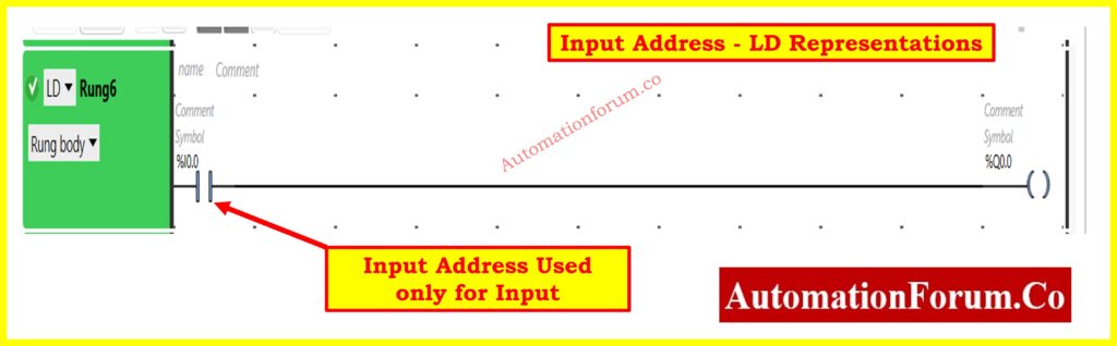
According to this rule, an input address (I0, I1, I2, etc.) must never be used as an output coil in the ladder logic program.
The above picture represents:
- Input I0 used as input in multiple rungs, which is correct.
- But not used as output, which would be incorrect.
You can reuse the input address in different input conditions, but never define it as an output coil.
Learn How the UP Counter Works: UP Counter in PLC Programming
Rule 6. Output Address can be used as an Input Address

This rule is valid and often used in PLC programming. you can use an output coil address (e.g., Q1) as an input contact in another rung.
This is done for feedback logic, holding circuits, or cyclic processes, where the state of the output determines another action.
For example:
- If a motor (Q1) is running, a fan should turn ON.
- Use Q1 as an input in a new rung to control Q2 (fan).
The above picture represents:
- Q1 used as a contact input in another rung to continue or control another part of the logic (like Q2).
This allows outputs to influence other logic conditions, making your program more dynamic and responsive to process changes.
So, you can write the PLC program in different ways by using multiple PLC programming instructions. But keeping these six rules in mind will help you structure your ladder diagram programs correctly and effectively.
Understanding these rules helps you:
- Avoid logical and hardware conflicts
- Maintain clarity and modularity in the program
- Build safe, efficient, and scalable automation systems
That’s it! Surely, you will find these rules for PLC ladder diagram programming useful when you start actually working on PLC programming.