- Functional Safety and IEC Standards
- Why SIS, SIF, and SIL are Critical for Modern Plants
- Safety Instrumented System (SIS)
- Major Components of SIS
- Safety Instrumented Function (SIF)
- Safety Integrity Level (SIL)
- How SIS, SIF and SIL Work Together
- When Do You Actually Need a SIS Instead of Alarms or Relief Devices?
- System Architectures to Achieve SIL Requirements
- Proof Testing in SIS
- SIL Assignment Process (IEC 61511)
- Applications of SIS, SIF and SIL Across Industries
- Challenges in Implementing SIS and SIL
- Best Practices for Functional Safety
- Importance of Functional Safety in Process Industries
- Why Engineers Must Understand SIS, SIF, and SIL
- FAQs on SIS, SIF and SIL
- Test Your Expertise on Safety Integrity Level (SIL)
Refineries, LNG terminals, petrochemical complexes, offshore platforms, fertilizer plants, and pharmaceutical production units are all examples of industrial plants that use dangerous chemicals, high pressures, combustible gases, and important energy sources. Any change from safe operating conditions could lead to disasters like fires, explosions, and poisonous discharges.
Functional Safety and IEC Standards
To stop things like this from happening, companies use the principles of functional safety, which are set by international standards IEC 61508 and IEC 61511. Three ideas are at the heart of functional safety:
- SIS – Safety Instrumented System
- SIF – Safety Instrumented Function
- SIL – Safety Integrity Level
These three parts work together to find dangers, fix problems, and lower risks to acceptable levels. This guide gives a thorough, engineering-based explanation of each term and how they fit into the functional safety lifecycle.
SIL Verification Made Simple – Full Guide + PFDavg Calculator: SIF PFDavg / SIL Verification – Complete Guide + Online Calculator
Why SIS, SIF, and SIL are Critical for Modern Plants
Automation is very important for modern industrial operations, but it can’t guarantee safe operation on its own. SIS, SIF, and SIL are terms that describe how industrial hazards are managed, watched, and reduced in a planned and controlled way. These ideas make sure that every important shutdown action works with the right level of reliability, integrity, and diagnostic coverage.
Safety Instrumented System (SIS)
A Safety Instrumented System is an automatic, stand-alone protection system that keeps an eye on process parameters all the time, finds harmful situations, and puts the system in a safe state when it has to. The SIS is only a protection layer, while the Basic Process Control System (BPCS) controls routine operations.
Purpose of SIS
A well-designed SIS must be able to:
- Find deviations from safe operating limits
- Check these differences in a certified logic solver.
- Turn on the necessary shutdown actions
- Move the process or equipment to a safe state
Even when there are problems with the equipment, electricity, or process, the SIS must still work.
The SIS is the last line of defense that stops dangerous situations from turning into accidents.
Typical SIS Applications in Process Industries
- Emergency Shutdown System (ESD)
- High Integrity Pressure Protection System (HIPPS)
- Fire & Gas Shutdown Functions
- Burner Management System (BMS)
- Turbine, compressor, and pump trip functions
SIS vs BPCS – Key Differences
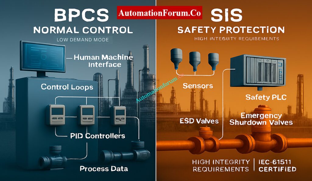
| Parameter | SIS | BPCS |
| Primary Purpose | Safety | Normal process control |
| Operating Mode | Low demand | Continuous |
| Certification | Required (IEC 61511) | Not required |
| Integrity Requirement | Very high | Moderate |
| Failure Consequence | Major accident | Production loss |
Master Intrinsic Safety – Ex ia, Ex ib & Ex ic Explained: Intrinsic Safety Protection Systems: Understanding Ex ia, Ex ib, and Ex ic
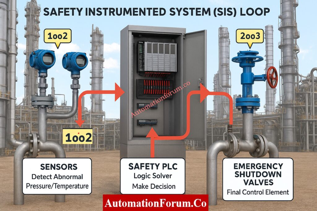
Major Components of SIS
A full SIS has three parts that work together to make a safety loop:
Sensors (Input Subsystem)
Sensors find unusual situations by constantly measuring gas concentrations, flow, level, vibration, temperature, and pressure.
Characteristics of SIS Sensors
- Made to be very reliable and respond quickly
- Often certified for use in SIL applications
- You can utilize redundant configurations like 1oo2 or 2oo3. It has built-in diagnostics to find problems or drift.
- Work in dangerous and demanding industrial settings
- Made to reduce failures that happen for the same reason
Sensors are the first thing that lets you know that the process is getting close to being unsafe.
Common Sensor Types Used in SIS
- Transmitters and switches for temperature
- Level transmitters that use radar and guided waves
- Flow transmitters that use Coriolis or DP
- Detecting gases that are toxic and can catch fire
- Sensors for machines that check vibration and speed
Logic Solver (Decision-Making Unit)
The logic solver looks at the sensor inputs and assesses if a safety action is needed.
Characteristics of a Logic Solver
- Typically a Safety PLC or dedicated safety controller
- Uses certified software tools for programming
- Offers high diagnostic coverage and fault-tolerant architecture
- Makes ensuring that response times are predictable
- Completely separate from the BPCS
- Keeps an eye on the health of the system and the integrity of communication at all times
The Safety Requirements Specification tells the logic solver how to run the Safety Instrumented Functions (SIFs).
Final Control Elements (Output Subsystem)
Final elements physically bring the process into a safe state.
Examples of Final Elements
- Emergency shutdown valves
- Blowdown and vent valves
- Motor trip relays
- Circuit breakers
- Fire dampers and isolation dampers
Characteristics of Final Elements
- Must operate reliably under emergency conditions
- Often include redundant actuators or solenoids
Final elements ultimately determine whether a safety action succeeds or fails.
Understanding Voting Logic with Simple Examples
- 1oo1 – Trips if 1 sensor detects a fault; fastest but least reliable.
- 1oo2 – Reduces nuisance trips and improves availability.
- 2oo3 – Common for SIL 3; allows one sensor to fail without losing safety function.
Future of Functional Safety – AI, Digital Twins & Industry 4.0 Insights: Emerging and Future Concepts in Functional Safety: AI, Digital Twins and Industry 4.0
Safety Instrumented Function (SIF)
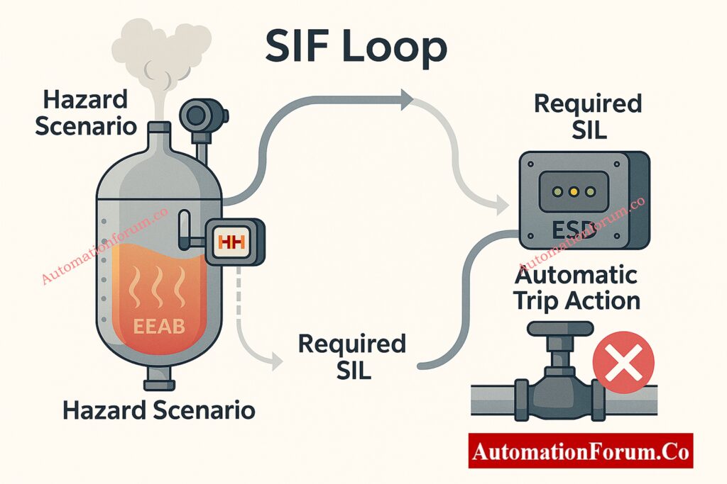
A Safety Instrumented Function is one specific safety action carried out by the SIS. While the SIS is the entire system, a SIF refers to one individual protective loop.
Definition of a SIF
A SIF includes:
- The hazardous condition it addresses
- Input sensors
- Logic action and voting logic
- Final control elements
- Required response time
- Operational mode and demand rate
- Associated SIL level
Each SIF must reduce risk to a level that is considered tolerable based on the plant’s risk criteria.
Examples of SIFs
- High-High Pressure Shutdown of a reactor
- Low-Low Level Trip to protect pump cavitation
- Gas detection leading to ventilation activation
- Combustion flame failure shutdown in furnaces
- Compressor surge control trip
- High temperature trip in a cracking furnace
A single SIS may contain dozens or hundreds of SIFs, each protecting against a unique hazard.
Safety PLC vs Standard PLC – Key Differences Every Engineer Must Know: Difference Between Standard and Safety PLCs: Features, Applications & Future Trends
Safety Integrity Level (SIL)
The Safety Integrity Level quantifies how reliably a SIF must perform to reduce process risk.
SIL is categorized into four levels: SIL 1, SIL 2, SIL 3, and SIL 4. In the process industry, SIL 1 to SIL 3 are most common, while SIL 4 is extremely rare and applies mainly to nuclear installations.
Why SIL Matters
SIL tells you how well a safety feature needs to work. A higher SIL level suggests that the chance of a dangerous failure is lower and therefore diagnostics, redundancy, design, and proof testing must be done more strictly.
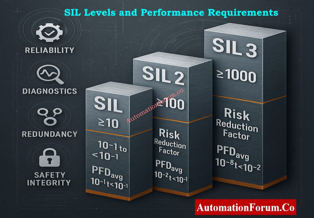
SIL Levels and Performance Requirements
| SIL Level | Risk Reduction Factor (RRF) | PFDavg Range (Low Demand) |
| SIL 1 | 10 to 100 | 10⁻¹ to 10⁻² |
| SIL 2 | 100 to 1,000 | 10⁻² to 10⁻³ |
| SIL 3 | 1,000 to 10,000 | 10⁻³ to 10⁻⁴ |
| SIL 4 | 10,000 to 100,000 | 10⁻⁴ to 10⁻⁵ |
Factors Considered in Assigning SIL
- Severity of failure consequences
- Frequency of initiating events
- How well the current protective layers work
- Average Probability of Failure on Demand (PFDavg)
- Coverage for diagnostics
- Requirements for hardware fault tolerance
- Times for maintenance and proof-testing
- Conditions in the environment and in the workplace
- Human factors and accessibility
SIL assignment makes sure that each SIF offers a level of protection that can be measured and is good enough.
IEC 61511 / S84 Explained – Complete SIS Standard Guide: S84 / IEC 61511 Standard for Safety Instrumented Systems – Complete Guide
How SIS, SIF and SIL Work Together
The relationship between SIS, SIF, and SIL can be summarized as follows:
- A SIS is the entire safety system
- A SIF is one safety function within the SIS
- A SIL expresses the performance required from that SIF
All three elements operate under the functional safety lifecycle, which governs design, installation, validation, operation, and modification activities.
Download Functional Safety Terms – Free Excel for Automation Engineers: Functional Safety Terminology – Excel Download for Industrial Automation
When Do You Actually Need a SIS Instead of Alarms or Relief Devices?
A SIS is required only when alarms, operator intervention, relief valves, or mechanical protection layers cannot reduce risk to a tolerable level. This determination is made during a Layer of Protection Analysis (LOPA).
Top SIS Interview Q&A – Prepare Like a Functional Safety Expert: Safety Instrumented System(SIS) Interview Questions and Answers
System Architectures to Achieve SIL Requirements
To meet the SIL requirements, engineers use various hardware architectures.
Common Architectures (1oo1, 1oo2, 2oo3)
- 1oo1 (One out of One): Used for SIL 1 systems that aren’t very risky
- 1oo2 (One out of Two): Adds backup, makes things more reliable
- 2oo3 (Two out of Three): Often used for SIL 3 and has great fault tolerance
Key Design Principles
- Independence from BPCS
- Staying away from common-cause failures
- Separate power supply and cabling
- Field equipment that are reliable and can diagnose problems
- Extra communication as needed
- Strong proof-test methods
Understand 1oo1, 1oo2, 2oo3 – Voting Logic Explained Clearly: Voting Logic in Safety Instrumented System
Proof Testing in SIS
Periodic proof testing is necessary since certain failures don’t show up until demand.
Purpose of Proof Testing
- Find hardware problems that haven’t been found yet
- Bring back the reliability of SIF
- Make sure that PFDavg stays inside the given SIL range.
The proof-test intervals have a direct effect on the SIL that is reached.
Proof Test Checklist for SIFs
- Check the full stroke and travel time of the shutdown valve
- Check how the solenoid valve reacts when it loses power
- Check the health of diagnostic alarms and communication
- Check and reset overrides or bypasses
- Check the logic solver trip record
- Document all test results and corrective actions
Refer the below link for the Global Control System Standards – 30+ Must-Know Codes for Engineers
SIL Assignment Process (IEC 61511)
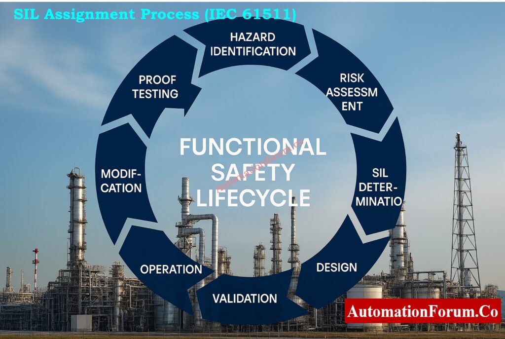
Assigning a SIL level is an organized process with several steps, including finding hazards, assessing risks, and checking.
Step-by-Step SIL Assignment
Hazard Identification
- Using HAZOP, What-If Studies, and FMEA
- Finding differences, their causes, and their effects
Risk Assessment
- Figuring out what the current danger levels are
- Comparing to acceptable risk standards
Evaluate Protection Layers
- Relief valves
- Operator response
- Mechanical interlocks
- Alarms
Determine the Need for a SIF
A separate SIF is needed if the current controls don’t lower the risk enough.
Assign SIL Requirement
Based on the risk reduction factor that is needed.
SIL Verification
- Calculating PFDavg
- Ensuring architecture meets hardware fault tolerance
- Selecting certified equipment
Detailed Design and Engineering
- Preparing Safety Requirements Specification
- Selecting sensors, logic solvers, and final elements
Installation and Validation
- Functional testing
- Loop checks
- System integration
Operation, Monitoring and Maintenance
- Proof testing
- Failure tracking
- Condition monitoring
Revalidation and Lifecycle Management
Updating SIF design when process conditions or equipment change.
Applications of SIS, SIF and SIL Across Industries
Functional safety is used in all businesses that deal with dangerous operations.
Common Applications
- Emergency Shutdown (ESD) Systems
- Fire and Gas Systems
- Burner Management Systems
- High Integrity Pressure Protection Systems (HIPPS)
- Reactor trip systems
- Compressor, turbine, and pump protection
Example SIF Scenarios
- Closing ESDV when line pressure exceeds safe limits
- Shutting a reactor feed pump when level is critically low
- Triggering blowdown during a gas release
- Shutting a heater on flame failure
Each SIF prevents a specific hazard from escalating.
Challenges in Implementing SIS and SIL
Functional safety implementation can face several practical challenges.
Common Challenges
- Incomplete hazard identification
- Insufficient or outdated documentation
- Use of non-certified devices
- Incorrect SIL verification calculations
- Lack of separation between SIS and BPCS
- Inadequate proof-testing practices
- Maintenance overrides left active
- Poor change-management procedures
- Incorrect reliability data
Common Errors in SIL Calculations
- Using incorrect or unrealistic failure rate (λ) data
- Ignoring mission time in PFD calculations
- Overestimating proof test coverage
- Using non-certified field devices in SIL-rated loops
Choosing the Best Safety PLC – Engineer’s Complete Selection Guide: How to Choose the Best Safety PLC for Your Industry
Best Practices for Functional Safety
The following practices help ensure an effective SIS throughout its lifecycle:
- Follow IEC 61511 in design, installation, and operation
- Maintain clear and complete Safety Requirements Specifications
- Use SIL-certified sensors, logic solvers, and final elements
- Ensure electrical and logical separation between SIS and BPCS
- Conduct regular training for engineers and operators
- Perform periodic proof testing according to defined intervals
- Use validated tools for SIL verification
- Maintain accurate documentation of maintenance and bypasses
- Regularly audit functional safety performance
Importance of Functional Safety in Process Industries
Functional safety ensures:
- Prevention of major accidents
- Protection of life, environment, and assets
- Reduced downtime and fewer emergency shutdowns
- Higher reliability of critical equipment
- Efficient startup and shutdown operations
- Regulatory compliance and audit readiness
SIS, SIF, and SIL together form a robust, engineering-based method to manage industrial risks.
SIS Explained – What Safety Instrumented Systems Really Do: What is SIS (Safety Instrumentation System)?
Why Engineers Must Understand SIS, SIF, and SIL
SIS, SIF, and SIL are cornerstones of functional safety in today’s complex industrial environments.
- The SIS is the complete protection system
- The SIF is each specific safety action
- The SIL defines how reliable that action must be
Understanding how these elements relate, how they are designed, and how they must be maintained is essential for every instrumentation, control-system, and process-safety engineer. By following the functional safety lifecycle, using certified equipment, and applying strong engineering and documentation practices, industries can ensure safe, reliable, and incident-free operations.
Mastering SIS, SIF, and SIL enables engineers to design safer plants, comply with IEC 61511, reduce operational risks, prevent major accidents, and ensure reliable shutdown performance across critical equipment.
FAQs on SIS, SIF and SIL
What is the difference between SIS, SIL and SIF?
SIS (Safety Instrumented System) is the complete safety protection system.
SIF (Safety Instrumented Function) is one specific safety action executed by the SIS.
SIL (Safety Integrity Level) defines how reliable a SIF must be to reduce risk to an acceptable level.
What is the full form of SIS and SIL?
SIS – Safety Instrumented System
SIL – Safety Integrity Level
What is SIF in oil and gas?
In oil and gas, a SIF is a safety function designed to prevent hazardous events such as overpressure, high temperature, gas leaks, or flame failure. Each SIF includes sensors, a logic solver, and final elements configured to automatically take the process to a safe state.
What are the three types of SIL?
In the process industry, three SIL levels are used:
SIL 1 – Basic risk reduction
SIL 2 – Moderate risk reduction
SIL 3 – High risk reduction
(SIL 4 exists in IEC 61508 but is rarely applied outside nuclear or extreme-risk domains.)
What are the 5 levels of safety?
The typical five levels of industrial process safety are:
- Basic Process Control System (BPCS)
- Alarms and operator intervention
- Safety Instrumented Functions (SIFs)
- Physical protection layers (relief valves, rupture disks)
- Plant emergency response and mitigation systems
What is SIL and ASIL?
SIL (Safety Integrity Level) is used in process industries (IEC 61511/61508) to define risk-reduction integrity for safety functions.
ASIL (Automotive Safety Integrity Level) is used in automotive safety (ISO 26262) and defines safety integrity requirements for vehicle electronic systems.
What is SIL and HAZOP?
SIL defines the reliability requirement of a safety function.
HAZOP (Hazard and Operability Study) is a structured method used to identify hazards and deviations in a process.
HAZOP findings often feed into LOPA, which is then used to determine the required SIL for each SIF.
Test Your Expertise on Safety Integrity Level (SIL)
Refer the below link to test your understanding with our Top 25 MCQs on Safety Integrity Level (SIL) for Instrumentation and Control Engineers