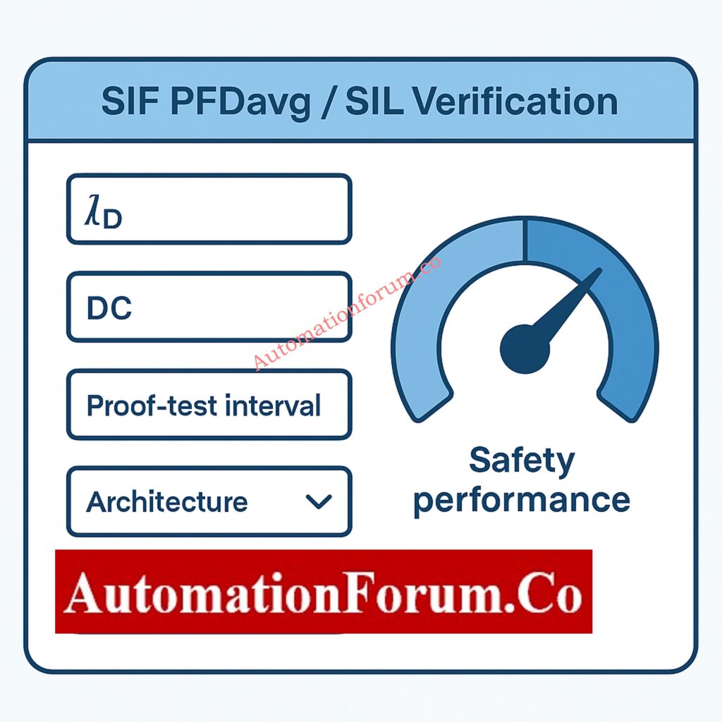
- SIF PFDavg / SIL Verification Calculator
- What is a Safety Instrumented Function (SIF)?
- Understanding SIL Levels (SIL 1, SIL 2, SIL 3)
- What is PFDavg? (Probability of Failure on Demand Average)
- Why SIL Verification is Required by IEC 61511
- How the SIF PFDavg Calculator Performs SIL Verification
- Features of This SIL Verification Calculator
- Functional Safety Glossary (Important Definitions)
- Best Practices for SIL Verification
- Why Use This SIF PFDavg Calculator?
- FAQ on SIF PFDavg / SIL VerificationWhat is a SIL verification?
- Test Your Expertise on Safety Integrity Level (SIL)
In industries including oil and gas, petrochemicals, pharmaceuticals, power plants, and manufacturing, functional safety is very important. If Safety Instrumented Functions (SIFs) don’t work right, a minor problem with any type of equipment might turn into a big problem. To verify the reliability of a SIF, engineers use PFDavg (Probability of Failure on Demand average) and classify systems according to Safety Integrity Level (SIL).
This complete guide walks you through the fundamentals of SIL verification and includes a powerful online calculator that dynamically computes PFDavg, SIL levels, diagnostic coverage effects, proof-test intervals, and more.
All calculations comply with IEC 61508 and IEC 61511 standards.
Instant Engineering Tool: Failure Rate (λ) Calculator for Process Instrumentation and Industrial Maintenance
SIF PFDavg / SIL Verification Calculator
SIF PFDavg / SIL Verification
Input Parameters
Results
What is a Safety Instrumented Function (SIF)?
A SIF is a protective safety loop that detects hazardous conditions and brings a process to a safe state. It consists of:
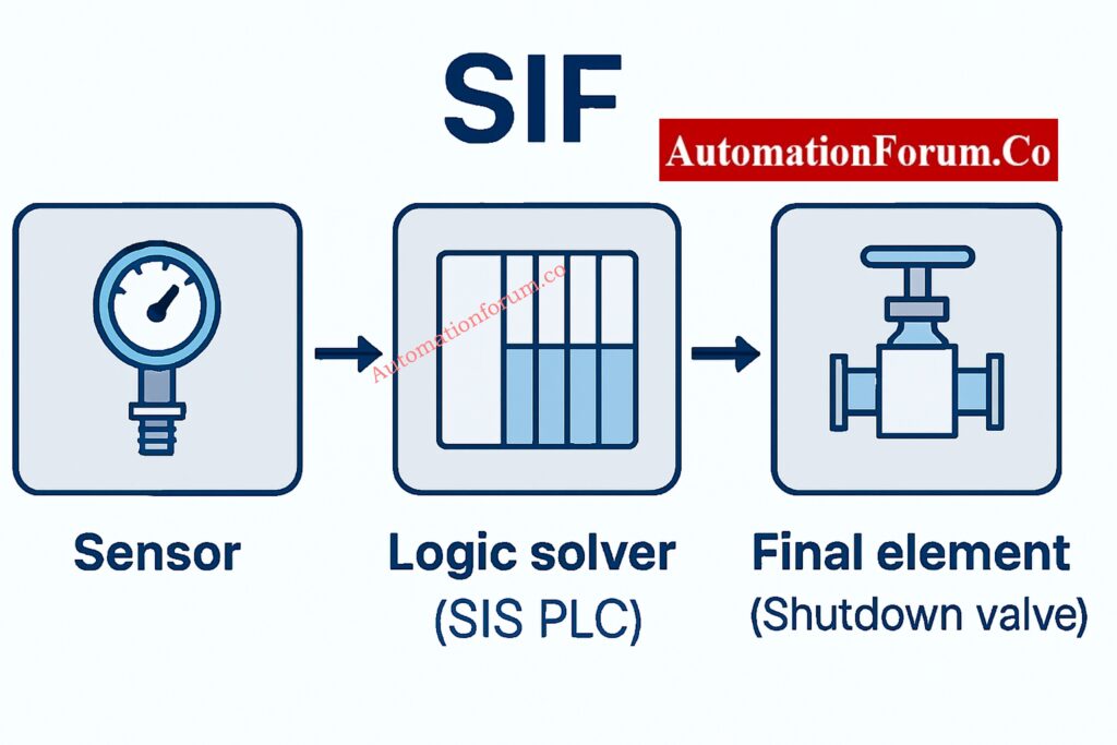
- Sensor(s) – Transmitters or switches
- Logic solver – PLC or safety controller (SIS)
- Final element(s) – Shutdown valves, relays, actuators
Each SIF is assigned a target SIL level based on risk analysis.
In-Depth IEC Guide: Testing and Repair Deferral – IEC Guidelines, Procedure, and Best Practices
Understanding SIL Levels (SIL 1, SIL 2, SIL 3)
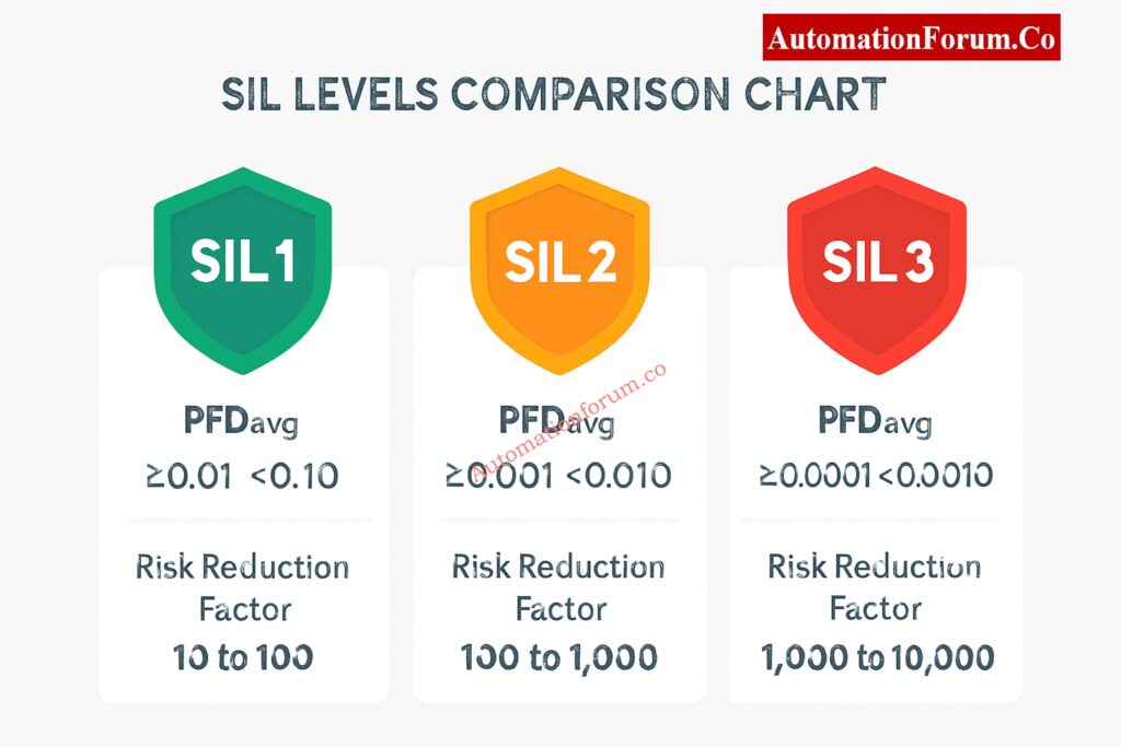
Safety Integrity Levels measure risk reduction capability:
| SIL Level | Target PFDavg | Risk Reduction Factor (RRF) |
| SIL 1 | 10⁻² – 10⁻¹ | 10–100 |
| SIL 2 | 10⁻³ – 10⁻² | 100–1,000 |
| SIL 3 | 10⁻⁴ – 10⁻³ | 1,000–10,000 |
A SIF must achieve a PFDavg lower than the maximum acceptable for its assigned SIL.
Refer the below link for the S84 / IEC 61511 Standard for Safety Instrumented Systems – Complete Guide
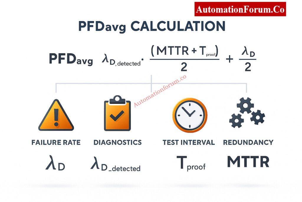
What is PFDavg? (Probability of Failure on Demand Average)
PFDavg (Average Probability of Failure on Demand) represents the likelihood that a safety function will fail when needed. Lower PFDavg = safer SIF.
Key Factors Affecting PFDavg
Critical factors affecting PFDavg:
- Dangerous failure rate (λD)
- Diagnostic coverage (DC)
- Proof test coverage (PTC)
- Proof test interval (T)
- Mean time to repair (MTTR)
- Architecture (1oo1, 1oo2, 2oo3, 1oo3)
- Common cause failures (β factor)
Download the Complete Pack: Functional Safety Terminology – Excel Download for Industrial Automation
Why SIL Verification is Required by IEC 61511
SIL verification ensures:
- Compliance with IEC 61508 / IEC 61511
- Risk reduction targets are met
- Safety loops perform reliably
- Regulatory acceptance
- Safe plant operation
This calculator performs the full SIL verification process automatically, saving hours of manual work.
Engineer Knowledge Challenge: Test Your Expertise in Safety Instrumented Systems (SIS): Knowledge Quiz
How the SIF PFDavg Calculator Performs SIL Verification
This tool follows IEC 61508/61511 formulas, including:
1. Unit Conversions
To handle engineering flexibility, λD may be entered as:
- FIT
- Per year
- Per hour
Proof-test intervals can be entered as years, months, or days.
The calculator internally converts everything to yearly units.
2. Detected vs Undetected Failures
Detected dangerous failures:
λD_detected = λD × DC
Undetected dangerous failures:
λD_undetected = λD × (1 – DC)
3. Architecture-Specific PFDavg Calculations
For 1oo1:
PFD_DD = λD_detected × MTTR
PFD_DU = λD_undetected × (T/2 when fully tested)
PFDavg = PFD_DD + PFD_DU
For 1oo2:
PFD_independent = (λDU² × T²) / 3
PFD_CCF = β × λDU × T / 2
Total = PFD_independent + PFD_CCF + PFD_DD
For 2oo3 and 1oo3 architectures, similar redundancy models are applied.

4. SIL Classification
The tool automatically ranks the SIL level:
| PFDavg | SIL Classification |
| ≤ 10⁻⁴ | SIL 3 |
| ≤ 10⁻³ | SIL 2 |
| ≤ 10⁻² | SIL 1 |
| > 10⁻² | Below SIL 1 |
You also get:
- Color-coded SIL badge
- Gauge meter
- Performance bar indicator
- Safety margin (%)
Master Your SIS Interview: Safety Instrumented System(SIS) Interview Questions and Answers
Features of This SIL Verification Calculator
IEC-Compliant Calculations
Follows IEC 61508 Part 6 and IEC 61511 guidelines.
Supports All Common Architectures
- 1oo1
- 1oo2
- 2oo3
- 1oo3
Includes Diagnostic Coverage & Proof Testing
Full CCF Support (β Factor)
Animated Results & Gauges
- Radial gauge
- Bar gauge
- Visual indicator of PFD performance
Calculation Steps Display
Good for:
- Audits
- SIL verification reports
- Hazard analysis documentation
Export Options
Export results as:
- CSV
- JSON
Excellent for reporting process safety teams or government agencies about problems.
Step-By-Step Engineering Breakdown: Understanding 2 out of 2 SOV: Working & Configuration
Functional Safety Glossary (Important Definitions)
Safety Instrumented System (SIS)
A safety automation system that runs SIFs to keep things running safely.
Proof Testing
Common Cause Failure (CCF)
Risk Reduction Factor (RRF)
RRF = 1 / PFDavg
Higher RRF = better safety performance.
Voting Architecture (1oo1, 1oo2, 2oo3)
Defines how many channels must operate successfully to complete the safety action.
Comprehensive Comparison Guide: Difference Between Triconex PLC and Other PLCs: A Complete Guide
Best Practices for SIL Verification
- Use λD values that have been certified by the manufacturer when you can.
- Change the proof test intervals based on how you want to maintain the plant.
- Consider environmental conditions that affect common-cause failures.
- Ensure the architecture aligns with risk reduction requirements.
- Add the findings of SIL verification to your Safety Requirements Specification (SRS).
Must-Read Engineering Standards: Key Instrumentation & Control (I&C) Standards Every Engineer Should Know
Why Use This SIF PFDavg Calculator?
This calculator is a quick, accurate, and compliant tool for engineers, safety experts, and automation professionals to figure out PFDavg and check SIL levels. Using this tool ensures better documentation, safer system design, and full compliance with functional safety standards.
Future Technologies Explained: Emerging and Future Concepts in Functional Safety: AI, Digital Twins and Industry 4.0
FAQ on SIF PFDavg / SIL Verification
What is a SIL verification?
SIL verification is the engineering analysis that proves a Safety Instrumented Function (SIF) meets its required Safety Integrity Level.
It checks failure rates, architecture, diagnostics, proof-test intervals, and reliability data.
The goal is to confirm the SIF achieves the target PFDavg or PFH.
It is usually done independently.
It ensures the design is quantitatively capable of reducing risk to the required level.
What is the difference between SIL verification and SIL validation?
Verification checks whether the SIF design, calculations, and documentation meet SIL requirements.
Validation checks whether the installed and operational system performs the safety function correctly.
Verification = analytical proof; Validation = real-world testing.
Verification happens during design; Validation happens after installation.
Both are required by IEC 61508/61511.
What is the SIL calculation?
SIL calculation estimates the probability that a safety function fails dangerously.
It uses failure rates, proof-test interval, diagnostics, redundancy, and repair times.
Metrics include PFDavg for low-demand and PFH for high-demand systems.
The result is compared against SIL thresholds.
It forms the quantitative backbone of SIL verification.
How to calculate PFD?
Basic low-demand PFDavg ≈ (dangerous undetected failure rate × proof-test interval) / 2.
More advanced models include redundancy, diagnostics, partial-stroke tests, and common-cause failures.
It requires accurate failure data for sensors, logic solvers, and final elements.
The PFDs of subsystem components are summed.
The final result is compared with SIL limits.
What is the difference between PFDavg and PFH?
PFDavg expresses the chance a safety function fails when demanded (low-demand mode).
PFH expresses the probability of failure per hour (high/continuous-demand).
PFDavg is used when demands are rare; PFH when demands can be frequent.
They serve different operating modes defined in standards.
Both measure dangerous failures but in different contexts.
How is SIL used in process safety?
SIL defines the required risk-reduction capability of a Safety Instrumented Function.
It ensures process hazards are reduced to tolerable levels.
Higher SIL means higher reliability and lower failure probability.
Used in design, operation, and maintenance of safety systems.
Ensures safety loops perform correctly to prevent major incidents.
Test Your Expertise on Safety Integrity Level (SIL)
Refer the below link to test your knowledge with our Top 25 MCQs on Safety Integrity Level (SIL) for Instrumentation and Control Engineers