- What Is a HART Loop Calculator and Why It Matters in Field Instrumentation
- Why HART Loop Calculation Is Important for Process Industries
- Understanding Loop Resistance, Voltage Drop, and Device Minimum Voltage
- How Cable Length and Cable Type Affect HART Loop Performance
- Why Receiver Resistance and Barrier Voltage Drop are Critical
- Advanced HART Protocol Loop Calculator Outputs Explained
- Advanced HART Protocol Loop Calculator Inputs Explained
- How to Use the HART Loop Calculator Step by Step
- How to Interpret PASS, MARGINAL and FAIL in HART Communication
- HART Communication Troubleshooting for Low Voltage Margin
- Best Practices for HART Loop Design and Commissioning
- How This HART Protocol Calculator Helps EPC, Maintenance and Commissioning Teams
- Conclusion: Why the HART Loop Calculator Is Essential for Reliable HART Communication
- FAQ About HART Loop Calculator
- What Is a HART Loop Calculator?
- Why Is Voltage Margin Important in a HART Loop?
- Can a Loop Pass Analog Current and Still Fail HART Communication?
- Why Does Cable Length Affect HART Performance?
- What Does PASS, MARGINAL, and FAIL Mean in the Calculator?
- Should Barrier Voltage Drop Be Included in the Calculation?
- Is HART Protocol 4 to 20 mA?
- Why Do You Need a 250 Ohm Resistor in HART Protocol?
- Is HART the Same as 4 to 20 mA?
- How Do You Use HART Protocol?
- Is HART AC or DC?
- How Do You Connect a 250 Ohm Resistor for a HART Communicator?
Advanced HART Protocol Loop Calculator
What Is a HART Loop Calculator and Why It Matters in Field Instrumentation
The HART Loop Calculator is a practical engineering tool for verifying whether a 4 to 20 mA loop has enough electrical headroom for both analog signal transmission and reliable digital HART communication. In real field applications, a loop may appear to work at the control system level, yet still fail during HART polling, device configuration, or commissioning because the available voltage at the transmitter is too low.
That is why this calculator matters. It helps instrumentation engineers, automation engineers, maintenance teams, commissioning engineers, EPC engineers, and students quickly evaluate the electrical health of a loop before problems appear in the field. By entering values such as supply voltage, loop current, cable length, cable resistance, receiver resistance, device minimum voltage, barrier voltage drop, and number of devices, the calculator estimates the full loop condition in a simple and engineering friendly way.
The result is more than a number. It gives a clear view of whether the loop has enough voltage for stable operation, acceptable resistance, and safe HART communication. That makes it useful during design, troubleshooting, loop check, and final commissioning.
Unlock Faster Device Configuration with Modern Tools: HART Transmitter Diagnostics: What Your Field Device is Telling You
Why HART Loop Calculation Is Important for Process Industries

How HART Communication Works in a 4 to 20 mA Loop
Why Voltage Headroom Matters for Reliable Device Operation
This is why the HART protocol calculator is valuable during instrumentation design and commissioning. It helps answer a simple but critical question. Does the loop have enough voltage and margin for reliable communication?
In practice, poor loop planning can lead to problems such as failed configuration, unstable multidrop behavior, noisy polling, or repeated communication loss when the process current increases. The calculator helps detect those risks early.
Refer the below link for the SmartBlue vs HART Communicator: Which Is Better for Instrumentation Engineers?
Understanding Loop Resistance, Voltage Drop, and Device Minimum Voltage
What Total Loop Resistance Means
Every current loop has resistance. Some of it comes from the cable. Some comes from the receiver or analog input. Some may come from safety barriers, intrinsic safety isolators, or communication interfaces. The total resistance in the loop determines how much voltage is lost before the transmitter receives what it needs.
How Voltage Drop Affects HART Performance
The loop resistance calculator feature is significant as resistance has a direct effect on voltage drop. Higher resistance means more voltage drop for a given current. At 20 mA, even a small increase in resistance can reduce the available voltage at the field device.
The device minimum voltage is equally important. Every transmitter requires a minimum operating voltage to work correctly. If the voltage at the device drops below that threshold, the loop may fail to operate reliably. In many field instruments, the unit may still seem alive at low load conditions, but HART communication can become unstable when the loop is pushed closer to its minimum.
Why Device Minimum Voltage Must Be Verified
The calculator compares the voltage available at the device with the minimum voltage required. That difference is called the voltage margin.
In simple terms, voltage margin is the spare voltage left after all loop losses are accounted for. A healthy margin means the loop has extra room for normal variation, temperature changes, cable aging, barrier losses, and practical field conditions.
Avoid Costly Communication Mistakes Before Your Next Shutdown: Difference Between Fieldbus and HART Communication Protocols: Complete Comparison Guide for Process Automation Engineers
How Cable Length and Cable Type Affect HART Loop Performance
Cable Resistance and Its Effect on Loop Voltage
Cable length is one of the most common causes of voltage loss in field loops. Longer cable means more resistance, and more resistance means more voltage drop. That is why the cable voltage drop calculator feature is so useful.
Cable type matters too. Resistance value of cables is vary for different sizes. A heavier conductor like 16 AWG has less resistance than a lighter conductor like 18 AWG. The lower the resistance the less voltage you will lose across the same distance. This can make a major difference in long runs or loops with several devices and barriers.
Why Cable Size Matters in Long Instrument Runs
For HART communication, cable quality also affects signal integrity. Excessive resistance, poor shielding, loose terminations, and noisy routing can make digital communication less reliable even when the analog current still looks normal. A loop may pass a basic current test and still fail during HART polling if the electrical headroom is too small.
That is why the calculator lets the user enter cable length and cable type or cable resistance. It supports better instrument loop design by showing how much the cable contributes to the total loop burden.
See What Your Smart Transmitter Is Really Reporting: Explained: The Four Main Process Variables (PV, SV, TV, QV) in HART Transmitters
Why Receiver Resistance and Barrier Voltage Drop are Critical

Receiver Resistance in 4 to 20 mA Loop Design
Receiver resistance is often overlooked, but it is one of the most important values in a HART loop. In many installations, the receiver may be a PLC analog input, DCS input card, isolator, or HART modem. If the receiver resistance is too high, it consumes loop voltage and reduces the voltage available for the field device.
Barrier Voltage Drop in Intrinsically Safe Loops
The same applies to barriers. A safety barrier or isolator can introduce a fixed voltage drop. In intrinsic safety applications, this drop is not optional. It must be included in the calculation from the beginning. If it is ignored, the design may look fine on paper but fail in the field.
How Series Loads Impact HART Communication
That is why this calculator includes barrier voltage drop as a separate input. It helps the engineer verify the loop under actual installation conditions, not just ideal conditions.
This makes the tool especially useful for hazardous area projects, brownfield upgrades, and loops that must pass through marshalling cabinets, intrinsic safety barriers, and long instrument cable runs.
Master Critical HART Settings That Improve Reliability: Best Practices for Configuring HART Parameters in DCS Software
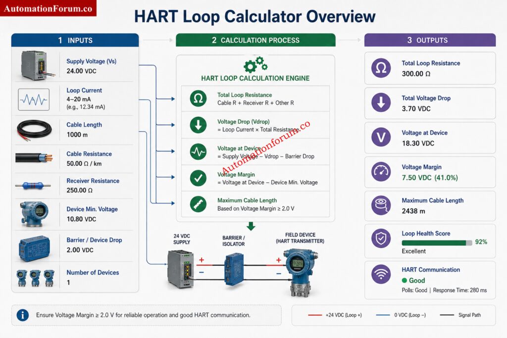
Advanced HART Protocol Loop Calculator Outputs Explained
Total Resistance
The Total Resistance is the sum of the resistance of the loop . This includes cable resistance , receiver resistance , and any other series loads . It is the total electrical load the transmitter must endure to operate properly and communicate using HART.
Voltage Drop
Voltage Drop is the amount of voltage lost across the loop due to current passing through the overall resistance of the loop. Higher loop current and higher resistance give a higher voltage drop. This is a key parameter for loop design.
Voltage at Device
Voltage at Device is the actual voltage available at the field transmitter, considering cable losses, resistance of receiver and voltage dips across barriers. In order to enable reliable operation, this value must be kept above the minimum working voltage of the transmitter.
Voltage Margin
The voltage margin is the difference between the voltage available for the device and the minimum voltage required by the transmitter. A big voltage margin offers more reliability and helps to accommodate future changes, temperature effects and component aging.
Drop Percentage
Drop Percentage is a measure of the amount of available supply voltage that is lost due to loop resistance and other losses. A high percentage may signify poor voltage headroom and greater risk of communication or operational problems.
Eliminate Common DP Level Measurement Troubleshooting Errors: Step-by-Step Troubleshooting Checklist for Closed Tank DP Type Level Transmitter
Maximum Cable Length
Maximum Cable Length determines the maximum cable run supported while still providing enough voltage at the device. This allows engineers to validate loop feasibility in design, expansion and commissioning activities.
Health Score
Health Score A fast overview of loop state based on voltage margin, loop resistance and communication needs. A higher score means that the loop is well designed with sufficient working headroom.
Communication Status
Communication Status shows the intended HART communication status as PASS, MARGINAL or FAIL. This result allows engineers to quickly verify whether the loop is capable of supporting steady and reliable HART communication.
Prevent Startup Delays with Proven Commissioning Methods: Step-by-Step Guide for Installing and Commissioning HART and WirelessHART Devices for Engineers and Technicians
Advanced HART Protocol Loop Calculator Inputs Explained
Supply Voltage
Supply Voltage is the DC power source available to the instrument loop. It provides the energy required for the transmitter, loop devices, and HART communication while overcoming all loop losses.
Loop Current
Loop Current represents the operating current flowing through the 4 to 20 mA circuit. The calculator commonly evaluates worst case conditions at 20 mA because voltage drop is highest at maximum current.
Sharpen Your Level Measurement Commissioning Expertise: Advanced Guided Wave Radar Level Transmitter Commissioning Quiz for Process Industries
Cable Length
Cable Length is the total distance between the field device and the control system. Longer cable runs mean more resistance and voltage loss which has a direct impact on loop performance.
Cable Type or Cable Resistance
Cable Type or Cable Resistance specifies the conductor properties utilized in the loop. varied wire sizes have varied resistance values that effect the voltage loss and communication dependability.
Receiver Resistance
Receiver Resistance is the load on PLC inputs, DCS input cards, isolators, recorders or other receiving devices. This increases the total resistance of the loop and the voltage available at the transmitter.
Device Minimum Voltage
Device Minimum Voltage is the lowest operational voltage that the transmitter manufacturer has specified. The loop voltage available must be higher than this number for proper functioning and HART communication.
Barrier Voltage Drop
Barrier Voltage Drop The voltage used by intrinsic safety barriers or isolators that are installed in the loop. This value is included to make sure that the voltage budgeting in design and commissioning is correct.
Number of Devices in the Loop
Number of Devices in Loop. This indicates how many devices are connected in the circuit. Additional devices can alter loading, communication performance and overall loop design issues.
Test Your Diagnostic Skills with Real-World Challenges: Closed-Loop Control Valve Troubleshooting: HART, Fieldbus and Diagnostics Skills Quiz
How to Use the HART Loop Calculator Step by Step
Using the calculator is straightforward.
- First, enter the supply voltage of the loop. This is usually 24 VDC in many process plants, but actual values may vary depending on the power supply and system architecture.
- Next, enter the loop current. For most checks, users test at 20 mA because that is the worst case for voltage drop. This gives the most conservative result.
- Then enter the cable length and select or enter the cable type or resistance. This helps the calculator estimate the voltage lost in the field wiring.
- After that, add the receiver resistance. This may come from the input card, isolator, modem, or other load in the loop.
- Enter the device minimum voltage from the transmitter datasheet or device specification. This value is essential for a realistic result.
- If the loop includes an intrinsic safety barrier, add the barrier voltage drop.
- Lastly, if your installation comprises many devices connected in a loop or a multi-drop configuration, specify the number of devices in the loop.
Enter the values, perform the computation and review the outputs. Focus first on voltage at device, voltage margin, and communication status. Then check total resistance and maximum cable length for design improvement.
Learn the Technology Behind Millions of Installed Devices: What is HART Protocol?
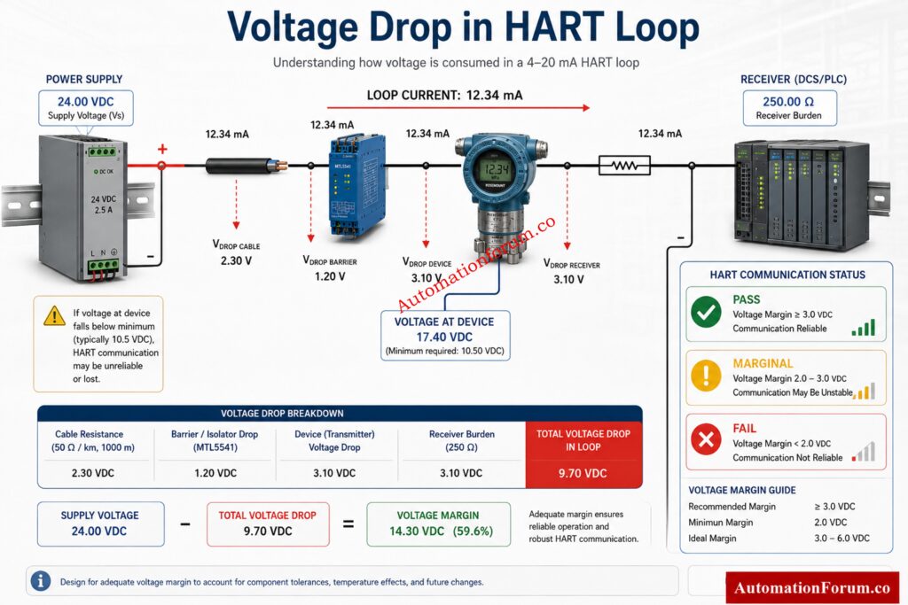
How to Interpret PASS, MARGINAL and FAIL in HART Communication
The communication result gives a fast decision view.
PASS Result
PASS means the loop has enough voltage margin and resistance conditions are acceptable for reliable HART communication. This is the condition you want during commissioning and normal operation.
MARGINAL Result
MARGINAL implies the loop is still functioning but the voltage margin is low. In this condition, HART communication may work sometimes and fail at other times, especially when process current changes, temperature increases, or field wiring ages. A marginal result should not be ignored.
Calculate Transmitter Output Accurately Every Single Time: Transmitter Calibration Calculator: How to Calculate Span, LRV, URV, and 4 to 20 mA.
FAIL Result
FAIL means the device probably does not have enough voltage to operate reliably, or the loop burden is too high for stable communication. In this case, HART polling, configuration, or device diagnostics may fail completely.
A good rule in field work is simple. If the result is marginal, treat it as a future failure, not a temporary success.
Explore the Evolution of Industrial Communication Networks: Comparison between Conventional (4-20ma) connection, Foundation-Fieldbus, and HART?
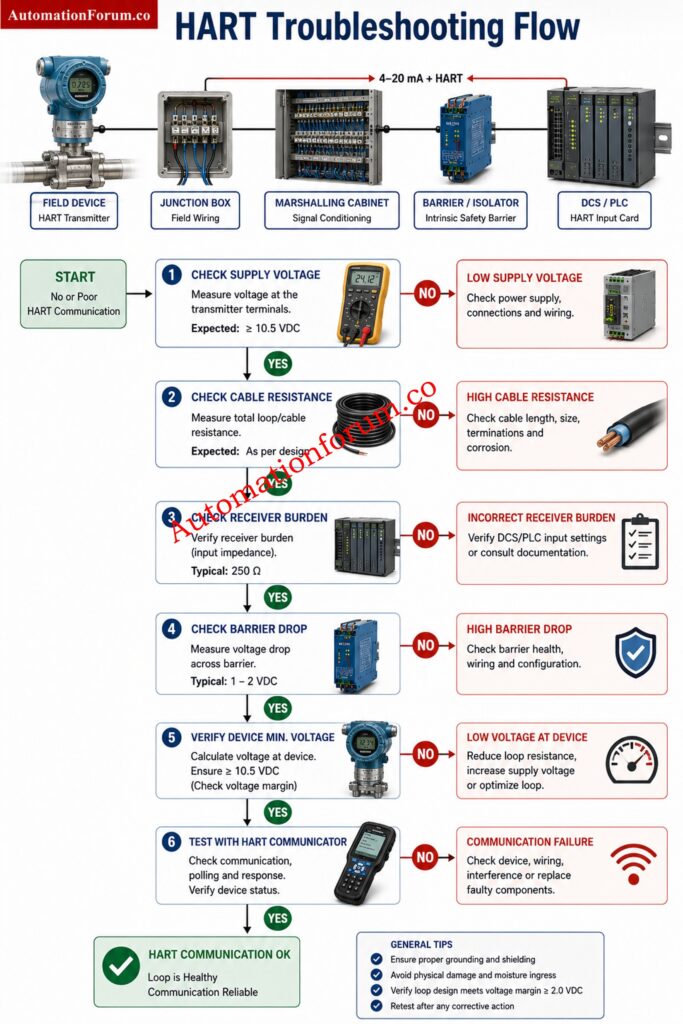
HART Communication Troubleshooting for Low Voltage Margin
- When the calculator shows low voltage margin, the first step is to reduce unnecessary burden in the loop. Check whether the receiver resistance is too high, whether the barrier drop is excessive, or whether the cable run is longer than planned.
- If the cable resistance is the problem, consider a lower resistance cable size, a shorter routing path, or a better loop layout. In long field runs, even a small change in conductor size can improve the result.
- If the barrier drop is too high, verify whether the selected barrier is correct for the application. Some loops are designed with more margin than others, but the barrier must still be included in the full budget.
- If communication is unstable even though the loop looks acceptable on paper, check for poor terminations, ground issues, loose marshalling connections, damaged cable, electromagnetic interference, or incorrect HART device configuration. HART is robust, but it is not immune to bad wiring practices.
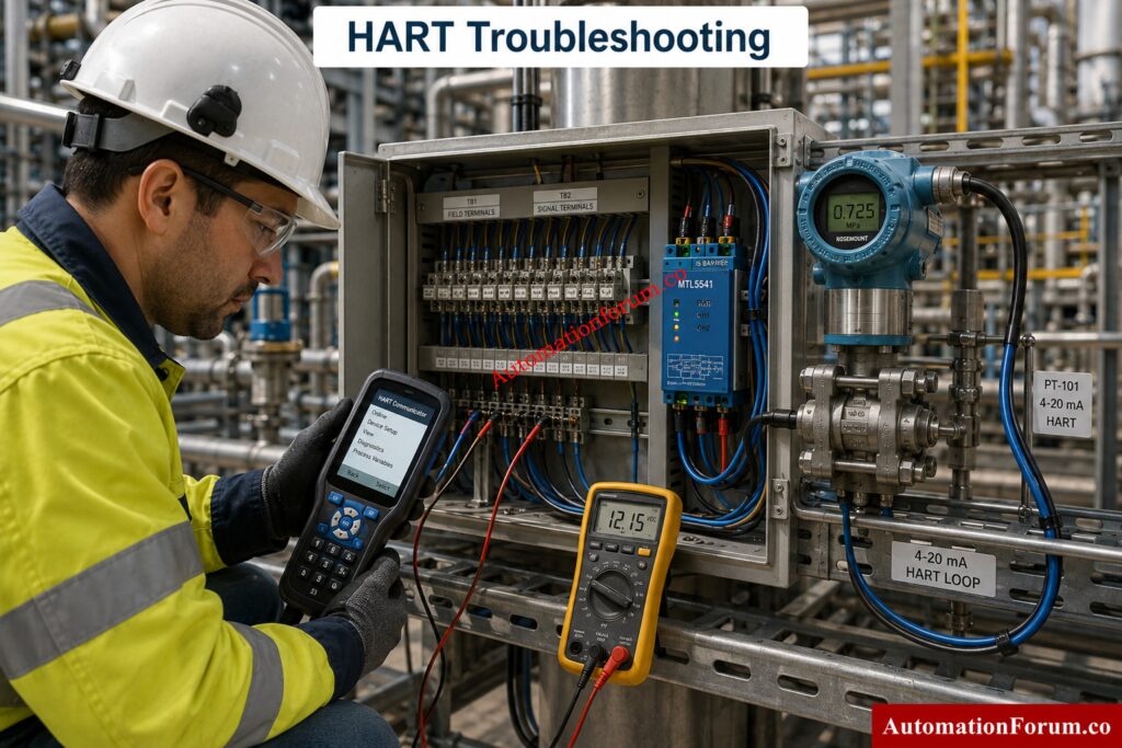
- When troubleshooting a weak loop, it is also wise to test the device directly with a handheld communicator or HART modem at the instrument terminals. That helps separate field wiring problems from device problems.
Understand Why HART Remains an Industry Standard: What is HART Communication Protocol and HART Multiplexer?
Best Practices for HART Loop Design and Commissioning
- Good instrument loop design starts with budget planning. Do not design only for nominal operation. Design for worst case current, actual cable length, barrier losses, and minimum device voltage.
- Always check the loop at 20 mA when possible because that represents the highest voltage drop condition in a 4 to 20 mA loop. This gives a more realistic view of the design margin.
- Use the correct cable resistance value rather than guessing. Cable size, conductor material, and route length all affect the result.
- Include all series loads in the calculation, especially safety barriers, isolators, input cards, and communication interfaces. A loop that looks fine with only cable and transmitter included can fail once real equipment is added.
- During commissioning, verify voltage at the device, not just supply voltage at the cabinet. The cabinet may show healthy supply, but the instrument may still be starved after all losses are included.
- For multidrop or multi device applications, confirm that the number of devices in the loop does not create unexpected loading or communication behavior. Even when current is low, the installation must still support stable HART signaling.
- Most importantly, keep a healthy margin. A loop that barely passes on paper often becomes a field problem later.
Solve Communication Issues Using This Simple Principle: Why is a 250-Ohm Resistor Important for HART Communication?
How This HART Protocol Calculator Helps EPC, Maintenance and Commissioning Teams
Commissioning teams often work under time pressure. A rapid, accurate calculator helps them validate the loop is ready before powering up the instrument or doing a HART configuration.
This saves unnecessary site troubleshooting, avoids repeated cable inspections and decreases the possibility of wrong assumptions while performing loop check activity. It also supports safer commissioning because the engineer can identify weak loops before they cause intermittent failures.
For EPC teams, the calculator is helpful during design review and vendor coordination. For maintenance teams, it helps isolate whether the problem is in the loop design or in the device itself. It provides students with a clear practical understanding of how 4 to 20 mA and HART communication are used together in real installations.
Challenge Yourself with Advanced HART Engineering Questions: Advanced HART Protocol Quiz: 25 MCQs with Detailed Explanations
Conclusion: Why the HART Loop Calculator Is Essential for Reliable HART Communication
The HART Loop Calculator is a very useful tool for anyone dealing with field instrumentation, 4 to 20 mA loops and HART communication. A simple calculation helps to evaluate the supply voltage, loop current, cable resistance, receiver burden, barrier drop, and device minimum voltage. By showing total resistance, voltage drop, voltage at device, voltage margin, maximum cable length, health score, and communication status, it gives a complete picture of loop performance.
In real plant work, that means better design, faster troubleshooting, safer commissioning, and more reliable communication in the field.
Build a Reliable Calibration Setup Without Guesswork: Wiring Diagram for Pressure Transmitter Calibration in Workbench using HART
FAQ About HART Loop Calculator
What Is a HART Loop Calculator?
A HART Loop Calculator is a tool used to determine whether a 4 to 20 mA loop has sufficient voltage and acceptable resistance for reliable HART communication and transmitter operation.
Why Is Voltage Margin Important in a HART Loop?
Voltage margin is the extra voltage remaining after all loop losses have been taken into consideration. A sufficient margin contributes to consistent transmitter operation and reliable HART communication.
Can a Loop Pass Analog Current and Still Fail HART Communication?
Yes. If the available voltage is too low or the loop resistance is too high, a loop can convey the 4 to 20 mA signal correctly yet HART communication becomes unreliable.
Why Does Cable Length Affect HART Performance?
The longer runs of cable mean more resistance in the loop, which means more voltage drop. This may cause a voltage drop at the field device and degrade the dependability of connection.
What Does PASS, MARGINAL, and FAIL Mean in the Calculator?
PASS means the loop is healthy and there is enough voltage margin. MARGINAL signifies the loop is running near its limits and FAIL means the loop may not sustain dependable operation or communications.
Should Barrier Voltage Drop Be Included in the Calculation?
Yes. Barrier voltage drop reduces the voltage available to the field device and must be included to accurately assess loop performance and communication capability.
Is HART Protocol 4 to 20 mA?
HART is not a replacement for 4 to 20 mA. It is a digital communication protocol that operates on top of the standard 4 to 20 mA analog current loop.
Why Do You Need a 250 Ohm Resistor in HART Protocol?
A 250 ohm resistor provides the minimum load resistance needed for HART communication. It allows the digital HART signal to be properly detected and interpreted by communicators and modems.
Is HART the Same as 4 to 20 mA?
No. The process variable is transmitted by the 4 to 20 mA signal, and HART provides digital communications capabilities on top of the same pair of wires for configuration and diagnostics.
How Do You Use HART Protocol?
The HART protocol is implemented by connecting a HART communicator or modem to a suitable loop. engineers can configure equipment, view diagnostics and get further process information.
Is HART AC or DC?
HART operates on a DC powered 4 to 20 mA loop but uses a small AC frequency shift keyed signal for digital communication. Both signals coexist on the same wiring.
How Do You Connect a 250 Ohm Resistor for a HART Communicator?
The 250 ohm resistor is installed in series within the current loop, typically near the control system input. The HART communicator is then connected across the resistor or designated communication terminals.
Refer the below link for the HART transmitter calibration procedure – For pressure transmitter