Profibus DP/PA Segment Calculator
Design and verify Profibus segments for DP, PA, and hybrid DP/PA installations. This calculator checks baud-rate cable limits, device loading, stub limits, repeaters, coupler range, and a simple compliance summary.
Input Parameters
Profibus Segment Calculation Results
Network Topology Diagram
Segment Analysis & Compliance Verification
IEC 61158 / EN 50170 Compliance & Recommendations
Export Segment Design
- Introduction to Profibus Network Design for Industrial Automation
- Why Profibus Segment Calculation is Important in Real Plant Environments
- Profibus Segment Calculation Across Engineering Lifecycle Stages
- Where and When to Use a Profibus Segment Calculator
- Profibus Standards and Design Rules Used in Segment Calculation
- Detailed Explanation of Profibus Segment Calculator Inputs
- Profibus Type (DP, PA, Hybrid)
- Application Type and Industry Conditions
- Baud Rate Selection for Profibus DP
- Cable Type (Type A vs Type B)
- Devices per Segment and Total Devices
- Trunk Length Calculation
- Stub Lines and Stub Length Considerations
- PA Device Power Loading
- Coupler Type Selection
- Installation Environment Impact
- Profibus Segment Calculator Outputs and Engineering Decisions
- Engineering Logic Behind Profibus Segment Calculation
- Real Plant Scenarios and Profibus Use Cases in Industry
- Common Profibus Design Mistakes and How to Avoid Them
- Best Practices for Profibus Network Design and Installation
- Maintenance and Troubleshooting Benefits of Profibus Segment Calculator
- Conclusion: Why Profibus Segment Calculation is Essential for Reliable Automation
- Frequently Asked Questions About Profibus Segment Calculation
- What is segment in PROFIBUS?
- How many PROFIBUS nodes can be installed per segment?
- What is DP and PA in PROFIBUS?
- What is the minimum distance between 2 devices on PROFIBUS DP (in meters)?
- What is the maximum number of nodes in PROFIBUS?
- What is Profibus segment calculation?
- Why is Profibus DP cable length important?
- What is the difference between Profibus DP and Profibus PA?
- When should I use a Profibus segment calculator?
- What causes Profibus communication problems?
- Can this calculator help with Profibus PA design?
Introduction to Profibus Network Design for Industrial Automation
What is Profibus and Why It is Widely Used in Industry
Profibus is one of the most trusted communication standards in industrial automation because it allows reliable data exchange between controllers, remote I O, transmitters, analyzers, actuators, and distributed field devices. It is widely used in process industries and manufacturing because it supports efficient communication, strong interoperability, and stable operation in demanding plant environments.
Difference Between Profibus DP and Profibus PA

In real engineering projects, Profibus is usually discussed in two main forms. Profibus DP is used for fast automation communication, remote I O, and machine control. Profibus PA is used for process instrumentation, especially where field devices need communication and power over the same cable.
What is a Hybrid Profibus Network Architecture

A hybrid Profibus system combines both approaches using a DP backbone and a PA segment through a coupler or segment coupler.
The key point is simple. Profibus is not only about connecting devices. It is about designing a stable segment that works reliably under real field conditions. That is why Profibus segment calculation is so important.
Top PROFIBUS MCQs Every Engineer Must Know: PROFIBUS Quiz: Top 25 Advanced Interview MCQs with Answers for Automation Professionals
Why Proper Profibus Segment Design is Critical
A poor design can create communication dropouts, intermittent faults, signal reflections, unstable device behavior, and repeated maintenance calls.
Your calculator is built for this exact purpose. It helps engineers check whether a Profibus network is within acceptable design limits before installation, during commissioning, or during troubleshooting. It is a practical fieldbus design calculator for design engineers, maintenance engineers, and instrumentation teams.
Avoid Explosive Area Errors Before They Start: IEC 60079-14 Explained: Complete Guide to Hazardous Area Installation for Instrumentation and Control Systems
Why Profibus Segment Calculation is Important in Real Plant Environments
Effect of Stub Lines on Signal Integrity
Profibus may look simple in a block diagram, but the real plant environment makes design decisions much more sensitive. Cable length, baud rate, device loading, stub length, termination, grounding, shielding, and environment all affect network stability.
Impact of Baud Rate on Profibus Cable Length
One of the most important factors is baud rate. A higher baud rate gives faster communication, but it reduces maximum cable length. That means a network running at a high speed cannot be wired the same way as a low speed network. This is one of the most common reasons why Profibus DP cable length must be checked carefully.
Device Count and Network Loading Challenges
Another major issue is device count. Even if the cable is within length limit, too many devices on one segment can create loading problems and make troubleshooting difficult. Stub lines can also create reflections and signal degradation. In plant conditions, these issues may not appear immediately during startup, but later they can create unstable operation.
Pick the Right Protocol With Confidence: Difference Between Fieldbus and HART Communication Protocols: Complete Comparison Guide for Process Automation Engineers
Profibus Segment Calculation Across Engineering Lifecycle Stages
This is why Profibus segment calculation is useful in three critical stages.
Profibus Network Design Stage Considerations
During design, the engineer confirms that the selected cable, baud rate, and segment layout are suitable for the intended plant application. This avoids unnecessary redesign later.
Profibus Commissioning and Validation Checks
During commissioning, the engineer verifies that the installed network matches the original design assumptions. If the segment is outside limits, corrections can be made before handover.
Troubleshooting Profibus Communication Issues
The calculator helps figure out if the problem is with the cable length, the device loading, the stub lines, or the coupler choices while troubleshooting. This is quite helpful when the plant is already running and the team has to check the engineering quickly.
Refer the below link for the Fieldbus Intrinsically Safe Concept (FISCO) Model for Foundation Fieldbus H1 and Profibus PA
https://automationforum.co/fieldbus-intrinsically-safe-concept-fisco-model-for-foundation-fieldbus-h1-and-profibus-pa/
Where and When to Use a Profibus Segment Calculator
Applications in EPC and Control System Design
This calculator is valuable in new projects, plant modifications, and troubleshooting work. It is especially useful in EPC design engineering, panel design, fieldbus layout planning, and revamp projects.
It is used in control system design offices when engineers are preparing the Profibus architecture.
Use in Panel Engineering and Fieldbus Layout Planning
It is also used during panel engineering when network devices, cabinet layout, and segment segmentation are being finalized.
Use in Plant Revamp and Expansion Projects
In revamp projects, it helps figure out if the current network can handle more devices or if a new segment needs to be added.
Role in FAT, SAT and Commissioning
It should be used before installation so that the network can be validated early. It is also useful during FAT and SAT because it provides a quick check before the system is handed over. During troubleshooting, it becomes a practical tool for identifying the root cause of communication instability.
This is one of the strongest reasons to use a fieldbus design calculator in plant engineering. It reduces guesswork and supports better decision making.
Protect Analog Signals From Noise Fast: Twisted Pair Cable in Industrial Signal Transmission: The Essential Guide for 4-20 mA and RS 485 Systems
Profibus Standards and Design Rules Used in Segment Calculation
IEC 61158 and EN 50170 Overview
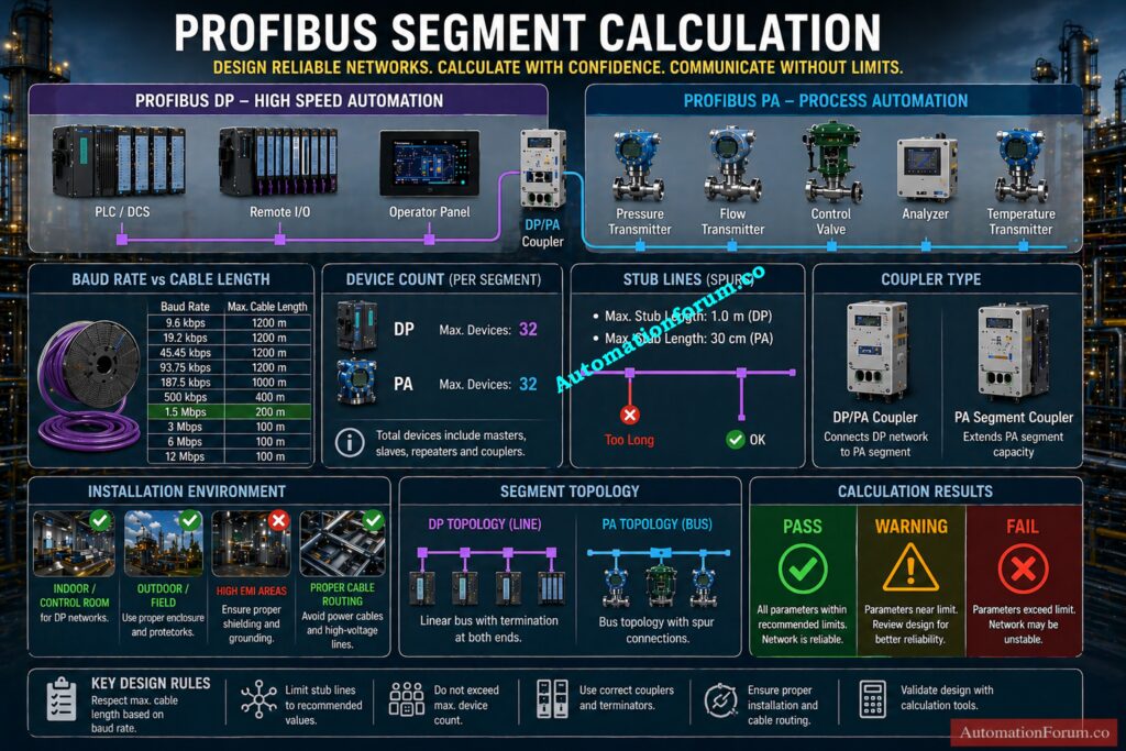
The calculator follows the engineering logic commonly associated with IEC 61158 and EN 50170 based Profibus design rules. These standards define the physical and communication framework for the network, including cable type, segment length, device limits, and signal characteristics.
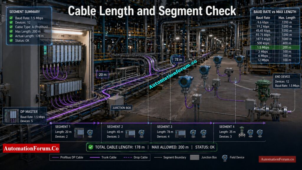
Profibus DP Cable Length vs Baud Rate Chart
In practice, the allowable cable length depends on baud rate. Lower speeds allow longer cable runs, while higher speeds require shorter distances. Typical guidance includes around 1200 meter for low speed operation, around 400 meter at 500 kbit/s, around 200 meter at 1.5 Mbit/s, and around 100 meter at higher speeds.
Profibus PA Segment Length and Coupler Limits
For Profibus PA, standard design can reach around 1900 meter with a standard coupler, while an extended coupler can push the range toward 3000 meter depending on the installation conditions. These are the kinds of values engineers need during actual network design.
Master PROFIBUS Applications in Minutes, Not Days: What is Profibus and what is its application in Instrumentation?
Detailed Explanation of Profibus Segment Calculator Inputs
The strength of your calculator is that it uses practical engineering inputs instead of abstract theory. Every field on the form has a clear purpose and helps the engineer reach a reliable design decision.
Profibus Type (DP, PA, Hybrid)
The first input is Profibus type. This can be DP, PA, or hybrid DP with PA coupler.
Profibus DP is the preferred choice for fast communication and remote I O. Profibus PA is the preferred choice for process instrumentation in plants where devices are distributed over long distances. Hybrid architecture is useful when a DP backbone feeds PA field segments.
Application Type and Industry Conditions
Application type matters because each industry creates different installation challenges. A manufacturing plant, a refinery, a power plant, and a hazardous area do not have the same noise level, cable routing, or maintenance conditions.
Commission Field Devices Without Rookie Mistakes: Step-by-Step Guide for Installing and Commissioning HART and WirelessHART Devices for Engineers and Technicians
Baud Rate Selection for Profibus DP
Baud rate is one of the most important values in Profibus DP cable length calculation. Higher speed means shorter allowed length. Lower speed means longer segment reach. This trade off is central to Profibus design.
Cable Type (Type A vs Type B)
Cable type affects signal quality and segment length. Your calculator includes Type A and Type B selection, which is useful because different cable families have different electrical behavior and distance capability.
Devices per Segment and Total Devices
This field checks the device loading on a segment. A segment with too many devices may still be connected electrically, but performance and reliability can suffer.
This is important for larger networks where multiple segments exist. Even if one segment looks fine, the total device population must still remain within the network limit.
Trunk Length Calculation
Trunk length is the main backbone length of the segment. This is the primary value that determines whether repeaters or segmentation are needed.
Stub Lines and Stub Length Considerations
Stub lines are a frequent source of communication issues. Long stubs increase the chance of reflections and waveform distortion. Your calculator checks both the number of stubs and the average stub length, which is very practical for field use.
PA Device Power Loading
In Profibus PA, power loading matters because the same line carries both communication and supply. Excessive current demand can lead to voltage drop and segment instability.
Coupler Type Selection
The coupler type determines how far the PA segment can be extended. A standard coupler and an extended range coupler do not provide the same design capability.
Installation Environment Impact
The environment input is very useful because industrial noise, outdoor exposure, and hazardous area conditions influence cable routing, shielding, grounding, and fault risk.
Beat The Interview With PROFIBUS Confidence: Profibus Interview Questions and Answers – Part 1
Profibus Segment Calculator Outputs and Engineering Decisions
The output section is designed for fast engineering decisions. It translates input values into practical results that can be used in design review or troubleshooting.
Maximum Cable Length Validation
This output shows whether the selected baud rate and cable type can support the planned installation. It is one of the most important outputs for Profibus segment calculation.
Repeaters Requirement and Network Extension
If the trunk length or device layout exceeds the normal limit, repeaters may be needed. Repeaters help extend a segment by regenerating the signal and restoring communication quality.
Stub Length Limits and Signal Reflection Control
This output helps the engineer control branch length and minimize signal reflections. It is especially useful in high speed Profibus DP networks.
Compliance Percentage (Pass / Warning / Fail)
The compliance value gives a fast pass, caution, or fail style result. This is useful for design verification and quick field checks.
Topology Diagram Interpretation
A topology preview helps the engineer visualize the actual layout. In many cases, this is the easiest way to spot poor segmentation or excessive branching.
Engineering Recommendations for Optimization
The recommendation section is useful because it does not only show the problem. It also suggests how to correct the design. That makes the calculator useful for both experienced engineers and junior users.
Second Round PROFIBUS Questions, Sharper Than Ever: Profibus Interview Questions and Answers – Part 2
Engineering Logic Behind Profibus Segment Calculation
The calculator works by comparing the selected design values against practical Profibus limits. It validates cable length against baud rate, checks device count, evaluates stub length, estimates repeater needs, and screens the PA coupler range.
This is the same basic logic applied by experienced instrumentation engineers during network review. It helps prevent problems such as signal reflection, incorrect termination, loading issues, and overextended segments. In other words, the calculator gives a fast engineering judgment before the issue becomes a field failure.
Clear the Protocol Confusion in Minutes Flat: Difference between profibus and foundation field bus
Real Plant Scenarios and Profibus Use Cases in Industry
Long Distance Field Devices in Refinery Applications
Field instruments are generally spread out over large areas in refineries, like pipe racks, tank farms, and processing units. The actual cable routing is usually much longer than the layout drawing due to structural routing and safety constraints.
Profibus PA is commonly used in these cases because it supports long distance communication with power over the same cable. However, the segment must be carefully validated for trunk length, coupler type, and total device loading.
If these are not checked, the network may work initially but later show instability during plant operation. The calculator helps confirm whether the selected design is within acceptable limits before installation.
High Speed Profibus DP Network in Manufacturing
Manufacturing systems require fast and consistent communication for machines, drives, and remote I O. Profibus DP is preferred because it supports high speed data exchange.
However, a key design mistake is selecting a high baud rate without checking the actual cable length. As speed increases, the allowable cable distance reduces. If this relationship is ignored, the network may experience communication errors during peak operation or electrical noise conditions.
The calculator ensures that the selected baud rate, cable type, and trunk length are aligned, and it also indicates if repeaters are required for stable operation.
Profibus PA Network in Hazardous Areas
In hazardous areas, network design must consider not only communication but also installation conditions. Cable routing, shielding, grounding, and environmental exposure all affect network reliability.
Profibus PA is widely used in these zones, but engineers must also verify segment length, device power consumption, and coupler limits. Excessive load or long cable runs can lead to voltage drop and unstable device communication.
The calculator supports this by checking PA power loading, trunk length, and coupler range, making it useful during both design and site validation.
Best Practices That Save Fieldbus Projects:Foundation Fieldbus Installation and Best Practices – Complete Guide for EPC and Maintenance Engineers
Troubleshooting Intermittent Profibus Communication

Intermittent faults are one of the most difficult problems in industrial networks. Devices may drop out randomly, communication may become unstable, or faults may appear only under certain operating conditions.
A lot of the time, the main cause has to do with physical design problems like too many devices, too long cables, or long stub lines instead of software concerns.
The calculator makes it easy for engineers to immediately compare the actual installation to the design restrictions. This makes it easier to figure out if the problem has to do with segment design and cuts down on the time it takes to fix it.
Stop SCADA Downtime Before It Spreads: SCADA Communication Problems and How to Fix Them
Common Profibus Design Mistakes and How to Avoid Them
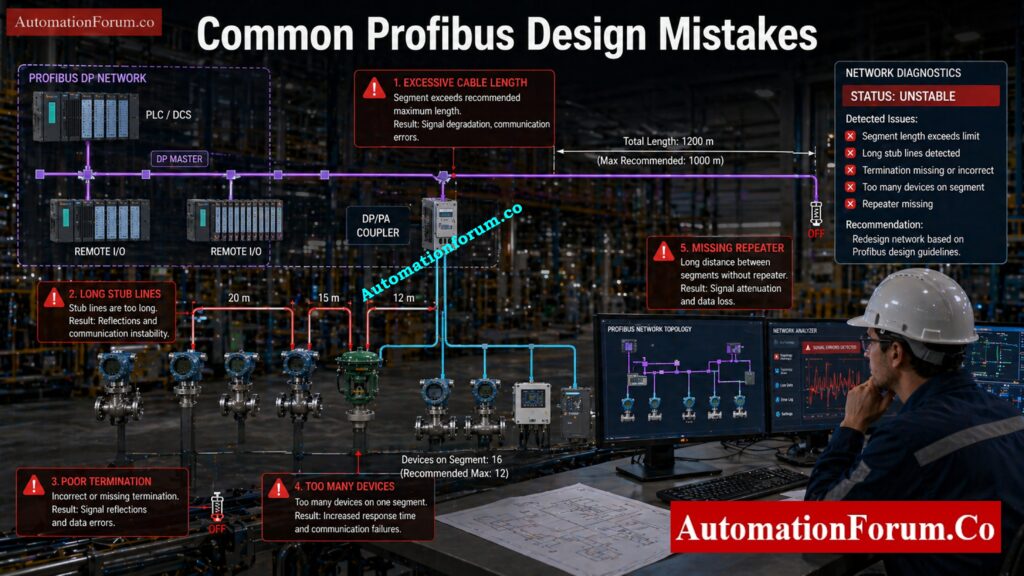
- Exceeding Cable Length Limits: One of the most typical blunders is going over the maximum cable length for a certain baud rate.
- Overloading Devices per Segment: Another frequent issue is placing too many devices on a single segment, which increases communication load and reduces stability.
- Long Stub Lines Causing Signal Reflection: Putting too many devices on one segment is another common problem that makes communication harder and less stable.
- Improper Termination Issues: In addition, missing or incorrect termination can cause serious communication issues that are difficult to trace.
- Missing Repeaters in Long Networks: Another common mistake is not taking into account the need for repeaters in long networks, which makes the signal weaker across the segment.
The calculator prevents these issues by validating all key parameters together. It checks cable length, device count, stub limits, and repeater needs in a single step. This gives the engineer a clear indication of whether the design is safe, requires attention, or needs correction.
Choose an HMI That Won’t Let You Down: How to Choose the Right HMI Display for Industrial Automation
Best Practices for Profibus Network Design and Installation
- Selecting Correct Profibus Cable Type: Always choose the right type of cable according to the rules and the needs of the application.
- Proper Shielding and Grounding Techniques: To cut down on noise interference, make sure your shielding and grounding are in good shape.
- Importance of Correct Termination: Make sure that termination is done correctly at both ends of the segment.
- Minimizing Stub Length: To avoid problems with signal reflection, keep stub lines as short as you can.
- Choosing the Right Baud Rate: Choose the baud rate depending on the actual layout of the cable, not only the performance needs.
- Optimizing Network with Repeaters: Use repeaters when you need to, but don’t make the network too complicated.
A well designed and simple network is easier to maintain, troubleshoot, and expand in the future.
Design Intrinsic Safety Loops Without Guesswork: IS Barrier Earth Fault Current Calculator | Intrinsic Safety Loop Design Tool
Maintenance and Troubleshooting Benefits of Profibus Segment Calculator
Validating Existing Networks
For maintenance engineers, this calculator is a practical tool for validating existing networks and diagnosing communication issues. It helps confirm whether the current segment still meets design limits, especially after plant modifications or expansions.
Supporting Network Expansion Planning
It is also helpful when making plans for improvements like adding new devices or expanding the network. Engineers can check the effect before putting it into action instead of making guesses.
Don’t Waste Time on the Wrong Protocol: Modbus TCP/IP vs Profinet: Which Protocol Suits your Industrial Network Best?
Reducing Troubleshooting Time
The calculator gives you a methodical technique to find likely root causes while you are troubleshooting. This cuts down on trial and error, speeds up discovering problems, and helps keep crucial plant processes running smoothly.
Decode Field Device Warnings Like a Pro: HART Transmitter Diagnostics: What Your Field Device is Telling You
Conclusion: Why Profibus Segment Calculation is Essential for Reliable Automation
Calculating Profibus segments is necessary for dependable industrial automation. Whether the system uses DP, PA, or hybrid architecture, the engineer must consider cable length, baud rate, device count, stub lines, power loading, coupler type, and environment.
Your calculator brings all of these checks together in a single practical tool. It helps design engineers, commissioning engineers, and maintenance engineers by making network review easier and more reliable. In plants where uptime matters, this kind of tool saves time, reduces troubleshooting effort, and helps prevent avoidable communication failures.
Find Modbus Address Conflicts Before Failure Hits: Duplicate Modbus Address in Temperature Multiplexers Causes Plant Shutdown – Real Incident & Root Cause
Frequently Asked Questions About Profibus Segment Calculation
What is segment in PROFIBUS?
A PROFIBUS segment is a section of the network cable where devices are connected without repeaters, limited by cable length and signal strength.
How many PROFIBUS nodes can be installed per segment?
A maximum of 32 nodes (including master and slaves) can be connected in one PROFIBUS segment without using repeaters.
What is DP and PA in PROFIBUS?
PROFIBUS DP (Decentralized Peripherals) is used for high-speed automation, while PROFIBUS PA (Process Automation) is used for field instruments with power and communication on the same cable.
Tighten HART Settings for Better Control: Best Practices for Configuring HART Parameters in DCS Software
What is the minimum distance between 2 devices on PROFIBUS DP (in meters)?
The recommended minimum distance between two devices is typically 1 meter (can go down to ~0.3 m in special cases).
What is the maximum number of nodes in PROFIBUS?
A PROFIBUS network can support up to 126 nodes (addresses) using repeaters and multiple segments.
What is Profibus segment calculation?
Profibus segment calculation is the process of checking whether a Profibus network meets the practical limits for cable length, device count, stub length, baud rate, and topology so that communication remains stable.
Why is Profibus DP cable length important?
Profibus DP cable length is important because higher baud rates reduce the maximum possible distance. If the cable is too long for the selected speed, communication instability can occur.
What is the difference between Profibus DP and Profibus PA?
Profibus DP is mainly used for fast communication in automation and remote I O, while Profibus PA is used for process instruments and can carry both power and communication over the same cable.
When should I use a Profibus segment calculator?
Use it during design, before installation, during FAT and SAT, and whenever you are troubleshooting a communication issue or planning a network change.
What causes Profibus communication problems?
Common causes include excessive cable length, too many devices, long stub lines, poor termination, wrong cable type, and incorrect repeater selection.
Can this calculator help with Profibus PA design?
Yes. It checks PA segment range, coupler type, device power, and trunk length, which are all important in Profibus PA design.
Refer the below link for the Understanding Zener vs Galvanic Isolation in IS Loops for 4 to 20 mA Systems