|
Shield Resistance
—
|
Noise Level
—
|
|
Ground Loop Effect
—
|
System Status
—
|
|
Parameters Used
|
Standards Referenced
|
- Noise Voltage Impact: Higher induced voltage and longer cable runs increase estimated noise contribution in the signal loop.
- Ground Loop Effect: Multiple grounding paths can create circulating currents and measurement instability.
- Single-Point Grounding: Preferred for most analog instrumentation — eliminates ground potential differences.
- Cable Routing: Keep signal cables separated from power cables and VFD output cables.
- Shielded Twisted Pair: Use STP for analog instrumentation loops to minimise differential noise pick-up.
- Introduction on Shield Grounding Noise Calculator
- What Is Shield Grounding in Instrumentation?
- Why Shield Grounding Noise Calculation Is Important
- Parameters Used in the Shield Grounding Noise Calculator
- How the Shield Grounding Noise Calculator Works
- How to Use the Shield Grounding Noise Calculator - Step by Step
- Who Should Use This Shield Grounding Calculator?
- Where and When to Use the Shield Grounding Noise Calculator
- Common Problems Caused by Poor Shield Grounding
- Single-Point Grounding vs Multi-Point Grounding
- How to Interpret Calculator Results
- Standards to Follow for Shield Grounding and Instrumentation Wiring
- Best Engineering Practices for Shield Grounding in Instrumentation
- Practical Field Example of Shield Grounding Noise Troubleshooting
- Frequently Asked Questions About Shield Grounding Noise Calculation
- Why Shield Grounding Should be Treated as a Critical Design Decision
Introduction on Shield Grounding Noise Calculator
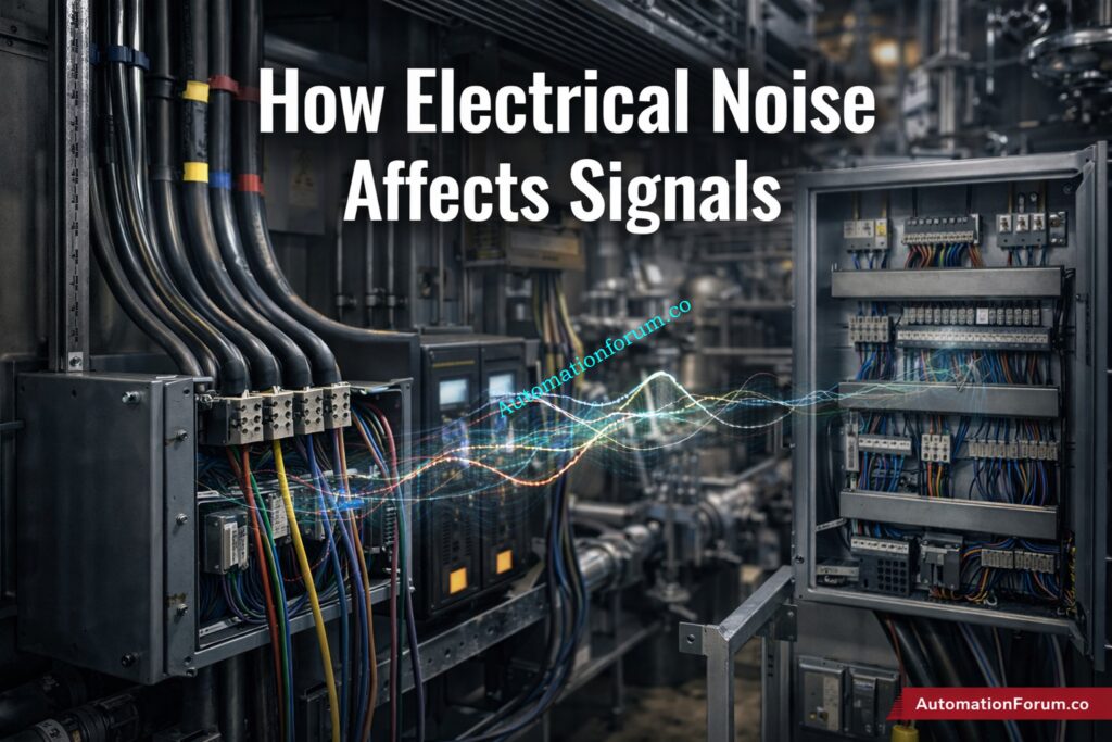
How Electrical Noise Affects 4-20 mA, Thermocouple and PLC/DCS Signals
In instrumentation and control systems, even a small amount of electrical noise can create serious problems. A noisy signal can cause a 4–20 mA loop to fluctuate, a thermocouple input to drift, or a PLC/DCS analog value to behave unpredictably. In real industrial plants, these issues often appear as unstable readings, false alarms, poor loop response, or repeated troubleshooting visits that never fully solve the root cause. That is why shield grounding in instrumentation is so important.
Why Shield Grounding Matters in Instrumentation and Control Systems
Proper cable shielding and grounding help protect low-level signals from EMI, RFI, and induced voltage from nearby power cables, motors, VFDs, and switching devices. But shielding is not simply about wrapping a cable in metal and connecting it anywhere to earth. Incorrect grounding can actually make the problem worse by creating ground loops, circulating currents, and additional noise paths.
Why a Shield Grounding Noise Calculator is Useful for Engineers
This is where a Shield Grounding Noise Calculator becomes useful. It helps engineers estimate the impact of induced voltage, shield resistance, loop current, cable length, and termination method on overall signal integrity. For commissioning, troubleshooting, or design review, this kind of calculation supports better decisions and more reliable instrumentation performance. As the source brief notes, electrical noise can distort low-power signals in instrumentation systems, which makes proper shielding and grounding essential.
Master Instrument Grounding and Bonding: Grounding and Bonding in Instrumentation and Control Systems
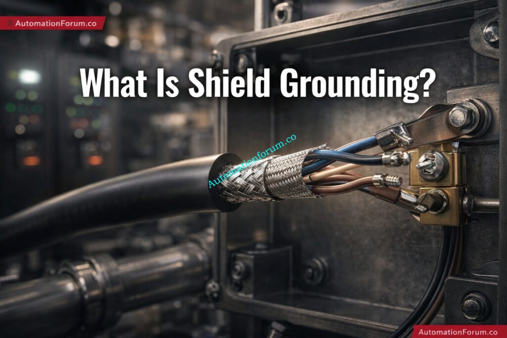
What Is Shield Grounding in Instrumentation?
Definition of Cable Shielding in Industrial Signal Wiring
Shield grounding is the method of connecting the metallic shield of an instrument cable to earth or reference ground so that unwanted electromagnetic energy is diverted away from the signal conductors. The shield surrounds the core conductors and helps keep outside sources of interference from getting in.
Shielding is used in instrumentation systems to keep:
- Analog loops with a range of 4 to 20 mA
- Signals from RTDs and thermocouples
- Signals with a pulse and a frequency
- Communication lines like HART, Modbus, and RS-485
- Signals for feedback and control at low voltage
Main Purpose of Shielding for EMI and RFI Protection
The goal of shielding is to lower:
- EMI: interference from electromagnetic waves
- RFI stands for radio frequency interference.
- Voltage caused by neighboring conductors
- Signal interference in sensitive measuring circuits
Refer the below link for the Method Statement for Instrumentation Cable Termination
Common Noise Sources in Instrumentation Cables
Noise mainly gets into instrumentation connections through:
1. Capacitive coupling: If a cable is close to a conductor that carries power, electric fields can send undesired voltage into the signal cable.
2. Inductive coupling: When current in nearby cables changes rapidly, magnetic fields can induce voltage in adjacent conductors.
3. Ground loops: When shield or signal reference points are grounded at more than one location with different potentials, circulating current can flow through the shield or reference path.
Improper grounding can increase noise instead of reducing it, which is why shield termination must be planned carefully.
Electrical Grounding Types Explained Clearly: What is grounding in electricity and Types of grounding
Why Shield Grounding Noise Calculation Is Important
A shield grounding noise calculation is not just a theoretical exercise. It directly supports real-world plant reliability.
Improving Measurement Accuracy
Noise on a signal line can distort the process variable and lead to false readings.
Maintaining Signal Integrity
A clean signal path ensures that the controller receives the correct process data.
Supporting Control Loop Stability
When the input signal is unstable, the control output may hunt, overshoot, or oscillate.
Reducing Safety Risks in Industrial Plants
Incorrect readings in critical service can affect alarms, trips, and protective actions.
Typical field problems caused by poor shielding
- False level indication in tanks
- Flow transmitter fluctuations
- Temperature noise in thermocouple circuits
- DCS analog drift
- Unstable valve position feedback
- Intermittent communication errors
A simple grounding mistake can waste hours in troubleshooting, so a calculation-based approach helps engineers predict risk before the system goes live.
Cable Shield Grounding Best Practices: Cable screen, Grounding cable screen
Parameters Used in the Shield Grounding Noise Calculator
A useful cable shielding noise calculation must evaluate several practical parameters. Each input reflects a real field condition.
Induced Noise Voltage
This is the voltage induced into the cable by external interference sources such as:
- VFDs
- Motors
- Transformers
- Switching contactors
- Power cabling
A higher induced voltage means a stronger interference threat.
Shield Resistance
Shield resistance depends on the quality and construction of the shield material. A low-resistance shield provides better noise diversion and more effective protection.
Why it matters: If the shield has high resistance, interference current may not drain effectively to earth, allowing noise to reach the signal core.
Instrument Cable Shielding Explained Guide: What is instrument cable shielding?
Ground Loop Current
Ground loop current is a major source of instability. It occurs when two ground points are at slightly different potentials, causing current to circulate through the shield or signal path.
Cable Length
Longer cables are more exposed to interference and have more opportunity to pick up induced noise.
General rule: The longer the run, the higher the likelihood of noise pickup, especially when the cable is routed near power systems.
Environment Noise Factor
Industrial environments are not equal. A clean control room is very different from a process area with:
- large motors
- VFD panels
- welding equipment
- heavy switching loads
A noise factor multiplier helps reflect this difference.
Grounding Type
The grounding scheme has a major impact on performance.
- Single-point grounding is often preferred for low-frequency instrumentation signals.
- Multi-point grounding may be used in high-frequency or EMC-intensive applications.
Single-point grounding prevents ground loop currents, which is why it is commonly recommended for instrumentation shields.
Shield Termination Method
How the shield is terminated matters just as much as whether it is grounded.
One-End Shield Termination
- Common in analog instrumentation
- Helps avoid loop current
- Often connected at the control panel end
Both-End Shield Termination
- Can improve high-frequency noise suppression
- May create loop currents in low-frequency systems
- Must be used carefully
Grounding both ends may create loop currents in low-frequency systems, which is why it should not be the default choice for every installation.
Zener vs Galvanic Isolation Guide: Understanding Zener vs Galvanic Isolation in IS Loops for 4 to 20 mA Systems
How the Shield Grounding Noise Calculator Works
The calculator uses practical engineering logic rather than complex laboratory modeling.
Core Logic of Noise Calculation
When the following things happen, noise gets worse:
- induced voltage increases
- shield resistance increases
- ground loop current increases
- cable length increases
- environment noise becomes stronger
Relationship Between Noise Voltage and Shield Resistance
We can write a simple idea about the relationship as:
Noise Level ∝ Induced Voltage / Shield Resistance
and
Ground Loop Effect ∝ Ground Loop Current × Resistance
Panel Heat Load Calculation Guide: Instrumentation Panel Heat Load Calculator – Complete Engineering Guide for Panel Cooling Design
Effect of Environment, Grounding, and Termination Factors
The calculator also uses things like:
- Environmental factor: clean, moderate, or industrial
- Grounding factor: one point or more than one point
- Termination factor: grounding at one end or both ends of the shield
These things assist turn raw data into a general risk level.
How to Interpret Calculator Output
The output can classify the system as:
- Healthy
- Moderate Risk
- High Risk
This gives engineers a quick idea of whether the installation needs correction.
Instrument Earthing Resistance Calculator Tool: Instrument Earthing Resistance Calculator for Process Industries Complete Engineering Guide
How to Use the Shield Grounding Noise Calculator - Step by Step
Using the calculator is simple and practical.
Step 1: Enter Induced Noise Voltage
Enter the expected or observed noise voltage that is present along the cable route.
Step 2: Input Shield Resistance
Give the shield resistance based on the cable's specifications or measurements taken in the field.
Step 3: Add Ground Loop Current
Enter the current that is expected or measured between ground locations.
Step 4: Enter Cable Length
Longer lengths usually indicate more exposure to noise.
Step 5: Select Grounding Type
Choose between:
- single-point grounding
- multi-point grounding
Step 6: Select Shield Termination Method
Choose:
- one-end shield termination
- both-end shield termination
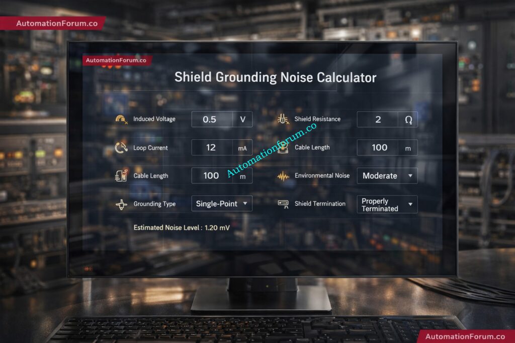
Step 7: Click Calculate and Review Results
The calculator produces values such as:
- shield resistance condition
- noise level
- ground loop effect
- system status
Instrument Earth Explained for Engineers: Understanding Instrument Earth (IE) in Industrial Automation – Complete Guide for Engineers
Who Should Use This Shield Grounding Calculator?
This tool is useful for professionals who deal with low-level signal reliability and plant-wide interference issues.
Target users:
- Instrumentation Engineers
- Control Engineers
- EPC Designers
- Commissioning Engineers
- Maintenance Engineers
- Troubleshooting Technicians
These users often need fast, practical assessment during design, installation, commissioning, or fault finding.
Advanced DP Calibration Quiz Test: Advanced DP Transmitter Calibration Quiz For Instrumentation Engineers And Technicians
Where and When to Use the Shield Grounding Noise Calculator
Where it is useful
- Oil and gas plants
- Power plants
- Chemical industries
- Pharmaceutical facilities
- Water treatment plants
- Manufacturing and process industries
When to use it
- During design review
- While routing cables
- Before commissioning
- During noise troubleshooting
- When analog signals become unstable
- When communication errors appear in the field
Redundant Transmitter Voting Logic Guide: Redundant Transmitters Explained: Reliability, Voting Logic and SIL for Instrumentation Engineers
Common Problems Caused by Poor Shield Grounding
Poor shield grounding can create a long list of plant issues.
Ground Loop Issues
Different grounding points create circulating current that distorts the measurement signal.
Signal Noise and Fluctuation
Noise appears as random fluctuation or jitter in the process variable.
PLC and DCS Instability
Controllers receive unstable inputs, which may cause process instability.
Instrument Drift
The instrument reading appears to move slowly or inconsistently without actual process change.
Communication Errors in Field Devices
Digital systems may show intermittent data loss, checksum errors, or message retries.
Ground loops cause circulating currents and instability, making them one of the most common root causes in field troubleshooting.
Signal Noise Troubleshooting Practical Guide: Noise and Signal Stability Observation for Running Inspection in Instrumentation and Control Systems
Single-Point Grounding vs Multi-Point Grounding
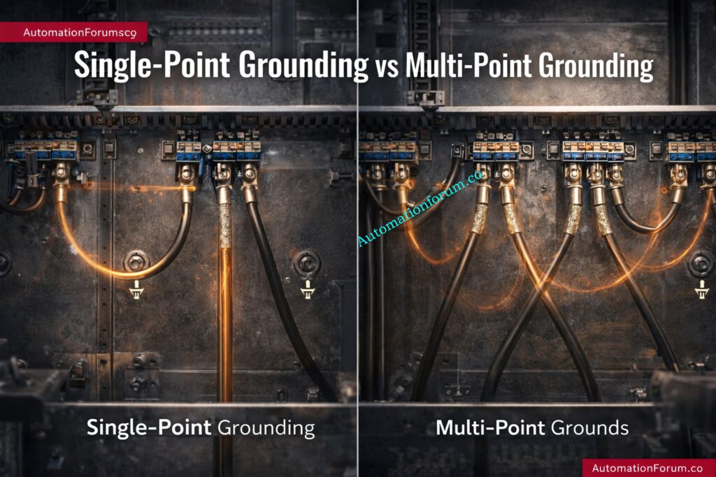
Choosing the correct grounding method is critical.
| Grounding Method | Best Use | Advantages | Risks |
| Single-point grounding | Low-frequency analog and instrumentation signals | Prevents ground loops, simple, reliable | Less effective for very high-frequency noise |
| Multi-point grounding | High-frequency EMC environments | Better high-frequency noise suppression | Can create loop currents in low-frequency systems |
What Is Single-Point Grounding?
This method is usually preferred for instrumentation because it minimizes circulating currents and keeps the shield reference controlled.
What Is Multi-Point Grounding?
This can be useful in special high-frequency applications, but it should be applied carefully in process systems.
Low-frequency systems generally prefer single grounding, while high-frequency applications may benefit from multiple grounding points.
Control Valve Hunting Fix Guide: Control Valve Hunting Due to PID Controller: Causes, Effects, Root Analysis and Complete Troubleshooting
How to Interpret Calculator Results
The result should always lead to an engineering action.
Low Noise Result
- Shielding is acceptable
- Grounding method is likely correct
- No immediate action required
Moderate Noise Result
- Review cable routing
- Check shield termination
- Inspect grounding continuity
- Reduce exposure to power cables
High Noise Result
- Immediate corrective action required
- Re-route cable
- Change termination method
- Improve grounding system
- Add separation from noisy conductors
Corrective Actions for Each Result Category
- Use shielded twisted-pair cable
- Shorten long cable runs where possible
- Ground the shield properly
- Separate signal and power cables
- Remove unnecessary parallel routing with VFD or motor wiring
Refer the below link for the Troubleshooting Analog Output Signals in PLC Loops – Advanced Scenario-Based Quiz for Process Industries
Standards to Follow for Shield Grounding and Instrumentation Wiring
Proper grounding and shielding should align with recognized standards.
IEC 60364-5-54
This standard addresses grounding, earthing conductors, and bonding practices.
IEC 61000 series
These standards relate to electromagnetic compatibility and immunity requirements.
Following standards helps ensure that grounding is not based on guesswork, but on accepted engineering practice.
AI Based Predictive Calibration Guide: Edge AI Based Predictive Instrumentation Calibration and Health Monitoring for Process Plants
Best Engineering Practices for Shield Grounding in Instrumentation
Good shielding practice can prevent many field issues before they happen.
- Ground the shield at one end for analog signals
- Avoid running signal cables parallel to power cables
- Use twisted pair shielded cables
- Maintain a proper earthing system
- Avoid floating grounds
- Keep shield termination clean and secure
- Inspect cable glands and enclosure bonding
- Confirm panel grounding continuity during commissioning
Shield grounded at the control panel end helps direct unwanted noise safely away from the signal circuit.
4 to 20 mA Verification SOP: Live Signal Verification 4 to 20 mA Loop Standard Operating Procedure (SOP)
Practical Field Example of Shield Grounding Noise Troubleshooting
Problem Scenario in a 4–20 mA Pressure Transmitter Loop
A 4–20 mA pressure transmitter signal is fluctuating in a pump area. The transmitter is installed near a VFD panel, and the signal cable runs alongside power cables for several meters. The PLC input shows occasional jumps in pressure value.
Likely Root Causes of Signal Fluctuation
- EMI from VFD output cables
- Inadequate shield termination
- Long parallel routing with power cables
- Possible ground loop current
How the Calculator Helps Identify High Risk
The engineer enters:
- induced noise voltage
- shield resistance
- loop current
- cable length
- industrial environment factor
- single-point grounding choice
- one-end shield termination
Result
The calculator shows High Risk.
Corrective Actions and Final Result
- Re-route the signal cable away from power wiring
- Terminate shield at one end only
- Verify panel earthing
- Check shield continuity
- Retest the loop after correction
After changes, the reading stabilizes and the signal variation drops significantly.
This is exactly the type of real-world issue a shield grounding noise calculator is designed to support.
Single Point Shield Grounding Rule: Why the Cable Shield is Grounded Only at the PLC or Control Panel Side
Frequently Asked Questions About Shield Grounding Noise Calculation
Why is shield grounding important in instrumentation?
It protects low-level signals from EMI, RFI, and induced noise, helping maintain stable and accurate measurements.
Should the shield be grounded at one end or both ends?
For many analog instrumentation signals, one-end grounding is preferred to avoid ground loops. Both-end grounding may be used in some high-frequency cases.
What causes a ground loop?
A ground loop occurs when more than one ground path exists and current circulates due to different ground potentials.
How can I reduce cable noise?
Use shielded twisted-pair cables, improve grounding, avoid parallel routing with power cables, and reduce cable length where possible.
Why do long cables increase noise?
Longer cable runs have more exposure to EMI and greater opportunity for induced voltage pickup.
What are the common signs of poor shield grounding?
Signal fluctuation, unstable DCS values, drift, communication errors, and intermittent process readings.
When should I use multi-point grounding?
Multi-point grounding is more suitable for certain high-frequency applications, not for every instrumentation loop.
Can wrong shield grounding make noise worse?
Yes. Incorrect grounding can create additional loop currents and interference rather than reducing it.
Why Shield Grounding Should be Treated as a Critical Design Decision
Shield grounding is one of the most important details in instrumentation and control wiring, yet it is often ignored until noise problems appear in the field. A properly designed shield grounding noise calculator helps engineers evaluate cable shielding noise calculation, ground loop effect in control systems, and shield termination methods in a practical, engineering-focused way.
Final Takeaway for Instrumentation Engineers
For EPC design, commissioning, maintenance, and troubleshooting, this calculator supports better decisions and faster fault isolation. By considering cable length, induced voltage, shield resistance, grounding type, and termination method, engineers can reduce signal interference and improve system reliability.
In real plants, stable signals mean better control, fewer alarms, and less downtime. That is why shield grounding in instrumentation should always be treated as a critical part of the design, not an afterthought.
Refer the below link for Understanding Zener vs Galvanic Isolation in IS Loops for 4 to 20 mA Systems