
- Why Understanding the Four Types of Registers in Modbus Protocol Is Important
- What is Modbus Protocol?
- Modbus RTU, Modbus ASCII, and Modbus TCP
- What Are Modbus Registers?
- Understanding the Four Types of Registers in Modbus Protocol
- Coil Registers
- Discrete Input Registers
- Input Registers
- Holding Registers
- Comparison of the Four Types of Modbus Registers
- Modbus Addressing Explained
- Common Modbus Function Codes
- Real Industrial Example of Modbus Register Communication
- Common Modbus Register Mistakes Engineers Should Avoid
- Best Practices for Reliable Modbus Communication
- Conclusion: Why Understanding the Four Types of Registers in Modbus Protocol Matters
- Frequently Asked Questions About Modbus Registers
Why Understanding the Four Types of Registers in Modbus Protocol Is Important
One of the first skills that every automation engineer should learn is to understand the Four Types of Registers in Modbus Protocol. Whether you are setting up a PLC, integrating a SCADA system, commissioning a DCS or connecting Industrial IoT devices, you will find Modbus registers nearly everywhere.
Modbus was created almost 40 years ago, and remains one of the most used industrial communication protocols because it is simple, robust, and compatible with equipment from different manufacturers. Today’s PLCs, RTUs, VFDs, energy meters, smart transmitters, and HMIs all still support Modbus RTU and Modbus TCP for the exchange of process data.
Much of the communication problems during commissioning are due to engineers not understanding how the Modbus register works. Even if the wiring and network settings are proper, the devices will not communicate if the register type is incorrect, the address is inaccurate or the function code is wrong.
This guide covers the four types of Modbus registers in simple terms and gives real-world industrial examples. Engineers can confidently configure devices, quickly debug communication issues, and develop dependable industrial automation systems when they understand the organization and usage of these registers.
Compare Both Protocols Before Choosing Your Next Industrial Network: Modbus TCP/IP vs Profinet: Which Protocol Suits your Industrial Network Best?
What is Modbus Protocol?
History of Modbus Protocol
Modbus is an open industrial communication protocol developed by Modicon in 1979 for programmable logic controllers. Over time, it became a standard method for exchanging information between industrial devices from different manufacturers.
Purpose of the Modbus Communication Protocol
The primary purpose of Modbus is to allow one device to request information from another device using a simple and standardized communication method. Because the protocol is easy to implement, it is supported by thousands of industrial products worldwide.
Modbus Master Slave Communication
In traditional Modbus Master Slave Communication, one master device controls all communication. The master sends a request, and the slave responds with the requested information. Slave devices never communicate with each other directly or send data without being asked.
Modbus Client Server Communication
For Ethernet based networks, Modbus follows a Client Server Communication model. The communication process is similar, but the terminology changes. The client initiates requests, while the server provides the requested data.
Today, three major versions of Modbus are commonly used:
Modbus RTU, Modbus ASCII, and Modbus TCP
Modbus RTU
The most common serial implementation of the protocol is Modbus RTU. It is usually used with RS485 networks and allows several field devices to be connected to the same communication wire. It provides quick communication with efficient transfer of binary data.
Modbus ASCII
Modbus ASCII communicates over serial links, but encodes data as readable ASCII characters. Although easier to diagnose manually, it is slower than Modbus RTU and is now used less frequently.
Modbus TCP
Modbus TCP uses Ethernet networks instead of serial communication. It provides faster data transfer, easier network integration and communication over conventional industrial Ethernet infrastructure.

Industrial Applications of Modbus Communication
Because of these communication options, Modbus is widely used in:
- Oil and gas facilities
- Chemical plants
- Power generation stations
- Water and wastewater treatment plants
- Food processing industries
- Pharmaceutical manufacturing
- Steel plants
- Building management systems
- Manufacturing automation
- Industrial IoT applications
Its simplicity and broad industry acceptance continue to make it one of the preferred protocols for connecting field devices with PLCs, SCADA systems, HMIs, and DCS platforms.
Refer the below link for the Key Factors to Consider When Setting Baud Rate in Modbus Networks
What Are Modbus Registers?
Why Modbus Registers Are Important
Modbus devices communicate by exchanging data in structured memory areas called Modbus Registers. You might think of these registers as places that can be given a label where a device can store information for other devices to read.
Each register stores information. Some registers hold digital data such as ON or OFF status. Other registers hold numerical values such as pressure, temperature, flow rate, motor speed or controller set points.
Understanding the Modbus Data Model
Modbus doesn’t directly access the physical memory inside a PLC or instrument but instead utilises a Modbus Data Model. Modbus uses a Modbus Data Model. This logical model presents data in a standardized format regardless of how each manufacturer stores information internally.
For example, a pressure transmitter may internally store its measurement in one memory location, while a PLC stores similar information somewhere entirely different. Modbus masks these hardware variations by using a universal register format which all compatible devices can understand.
This makes it a lot easier to integrate devices. The SCADA system has to know the Modbus register address, and not the internal memory organization of each of the linked devices.
Modbus Memory Map and Register Addressing
Another key notion is the Modbus Memory Map. Every Modbus device presents a memory map of available registers, including their addresses, data kinds, engineering units, and access rights. This document is used by engineers during commissioning to properly configure PLCs, HMIs or SCADA software.
Logical Addressing vs Physical Memory
It is also vital to realize that Modbus addresses are logical addresses, not real physical memory locations. The addresses may be displayed differently by various software packages, which can sometimes lead to misunderstanding during configuration. This is discussed later in the essay.
Challenge Your Industrial Networking Skills With This Expert Level Quiz: MODBUS Protocol Quiz :Test Your Knowledge
Understanding the Four Types of Registers in Modbus Protocol

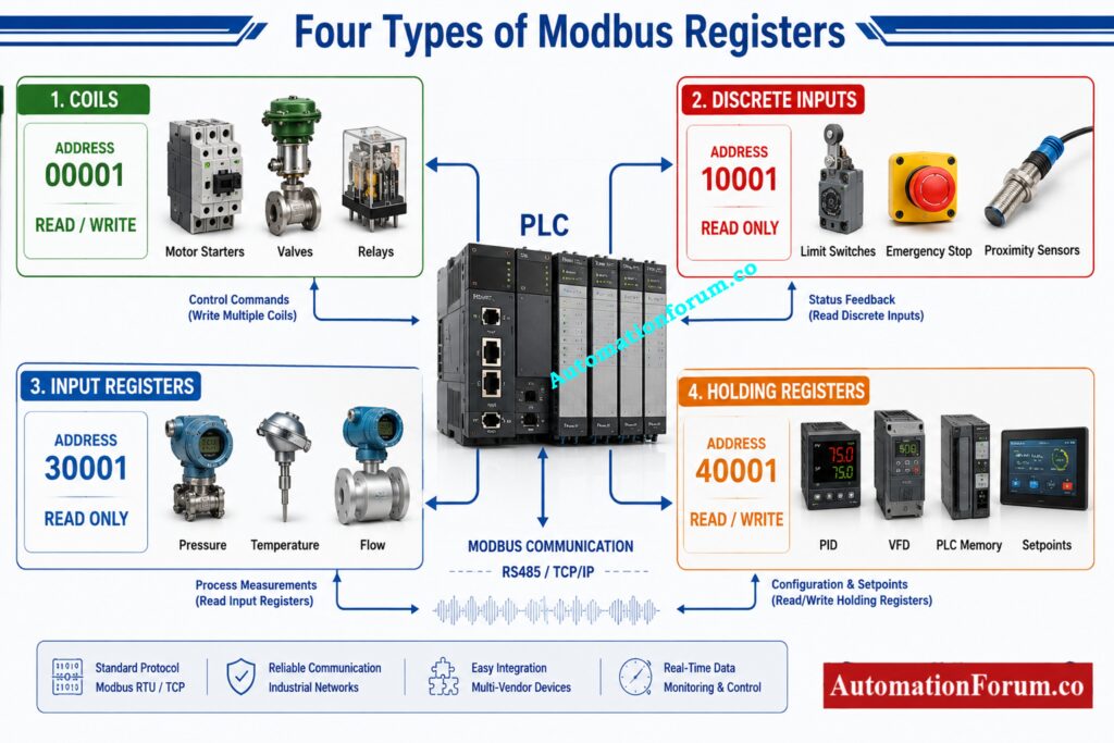
The Modbus data model structures information into four different register types. Each type is made for a special purpose and has its own access mechanism and function codes.
It is important to understand when to use each form of register for successful Industrial PLC Communication, SCADA Modbus Communication, and dependable Automation Communication.
Master Every Diagnostic Step Before Communication Failures Become Critical: Step by Step Procedure for Modbus Troubleshooting
Coil Registers
Coil registers are digital outputs, which are ON or OFF. They hold only 1 bit of information . They have read and write operations .
These registers are also often used to directly operate field devices from a PLC or SCADA system.
The usual range of the addresses begins at:
00001
Common Modbus Function Codes include:
- Read Coils
- Write Single Coil
- Write Multiple Coils
Typical Industrial Applications
Coil registers are frequently used for:
- Motor start commands
- Pump start and stop control
- Solenoid valve operation
- Alarm acknowledgement
- Valve open and close commands
- Conveyor start signals
- Fan control
- Lighting control
Advantages
- Simple digital control
- Fast communication
- Easy PLC programming
- Ideal for remote operation
Limitations
- Stores only binary values
- Cannot store analog measurements
- Limited to ON or OFF information
Coil Register Summary
| Property | Description |
| Data Type | One bit digital value |
| Access | Read and Write |
| Typical Address Prefix | 00001 |
| Typical Devices | Motor starters, valves, relays |
| Common Function Codes | Read Coils, Write Single Coil, Write Multiple Coils |
Learn Everything Every Automation Engineer Must Know About Modbus: Modbus Protocol – Complete Guide for Automation Engineers
Discrete Input Registers
Discrete Inputs are digital signals that can be observed but not modified through Modbus connection. These registers are read-only and often coupled to physical input devices.
PLCs and SCADA systems may read their status but not change it as they show the actual field conditions.
Start of standard address range:
10001
Common Function Code:
- Read Discrete Inputs
Typical Industrial Applications
Discrete inputs are commonly connected to:
- Limit switches
- Emergency stop contacts
- Pressure switches
- Level switches
- Proximity sensors
- Door interlocks
- Fire detection contacts
- Safety relay status
For example, a limit switch mounted on a control valve can signal that the valve has reached its completely open state. The PLC reads this information through a discrete input register to confirm successful operation.
Advantages
- Reliable monitoring of field status
- Prevents accidental modification
- Simple diagnostic information
Limitations
- Read only operation
- Stores only binary values
- Cannot be used for process measurements
Discrete Input Register Summary
| Property | Description |
| Data Type | One bit digital value |
| Access | Read Only |
| Typical Address Prefix | 10001 |
| Typical Devices | Limit switches, emergency stops, proximity sensors |
| Common Function Code | Read Discrete Inputs |
Ace Every Automation Interview With These Proven Technical Questions: Modbus Interview Questions and Answers: Essential Knowledge
Input Registers
Input registers store read only numerical values. Unlike coils and discrete inputs, these registers carry 16 bit data and are hence well suited for analog process measurements.
Input registers are used to transfer the measured values to PLCs, SCADA systems and distributed control systems by most sophisticated field instruments.
Typical address range begins with:
30001
Common Function Code:
- Read Input Registers
Typical Industrial Applications
Input registers commonly store values from:
- Pressure transmitters
- Temperature transmitters
- Flow transmitters
- Level transmitters
- Power meters
- Energy analyzers
- Gas analyzers
- Environmental monitoring instruments
For example, a smart pressure transmitter may be continuously updating an input register with the process pressure being monitored. The PLC reads this register periodically and can use the value to display it on an HMI, create warnings or conduct control computations.
Advantages
- Stores analog measurements
- Supports a wide range of engineering values
- Ideal for monitoring process variables
- Widely supported by intelligent field devices
Limitations
- Read only access
- Cannot be used to change device settings
- Larger values may require multiple registers depending on the data format
Input Register Summary
| Property | Description |
| Data Type | Sixteen bit analog value |
| Access | Read Only |
| Typical Address Prefix | 30001 |
| Typical Devices | Pressure, temperature, flow, and level transmitters, power meters |
| Common Function Code | Read Input Registers |
Understand Critical Differences Before Selecting Your Modbus Communication Method: MODBUS SERIAL VS MODBUS TCP/IP
Holding Registers
Holding registers are the most adaptable and most extensively utilized of the registers in the Modbus data paradigm. These can hold 16 bit values that may be read as well as written and are thus appropriate to monitor process data as well as to change device parameters.
Holding registers are typically used to hold configuration settings, operating parameters, controller values and computed process data, input registers only contain measured values. Most PLCs provide their internal memory using holding registers because they allow external systems to get information and change it if needed. The new value is written to a holding register, and the PLC uses that value as the controller set point.
Typical address range begins with:
40001
Common Function Codes include:
- Read Holding Registers
- Write Single Register
- Write Multiple Registers
Typical Industrial Applications
Holding registers are commonly used for:
- Pressure and temperature set points
- PID controller tuning values
- Timer presets
- Counter values
- Motor speed references
- Variable frequency drive commands
- Engineering unit scaling
- PLC internal memory variables
For example, an operator may change the desired tank level from an HMI. The new value is written to a holding register and the PLC uses that value as the controller set point.
Advantages
- Supports reading and writing
- For the analog values and configuration data,
- Most often utilized register type in PLC applications
- Suitable for control and monitoring
Limitations
- Wrong write operations affect the process behaviour
- The correct access control is very important for crucial applications
Holding Register Summary
| Property | Description |
| Data Type | Sixteen bit value |
| Access | Read and Write |
| Typical Address Prefix | 40001 |
| Typical Devices | PLC memory, drives, controllers, HMIs |
| Common Function Codes | Read Holding Registers, Write Single Register, Write Multiple Registers |
Stop Choosing the Wrong Network With This Clear Comparison: Difference between Modbus & Modbus Plus

Comparison of the Four Types of Modbus Registers
| Register Type | Address Prefix | Read | Write | Data Type | Typical Devices | Common Function Codes |
| Coil | 00001 | Yes | Yes | One bit | Motor starters, valves, relays | 01, 05, 15 |
| Discrete Input | 10001 | Yes | No | One bit | Switches, sensors | 02 |
| Input Register | 30001 | Yes | No | Sixteen bit | Pressure, flow, temperature transmitters | 04 |
| Holding Register | 40001 | Yes | Yes | Sixteen bit | PLC memory, drives, controllers | 03, 06, 16 |
Protect Critical Infrastructure Before Cyber Threats Cause Massive Damage: Top Cybersecurity Threat Identification Methods Every Security Professional Should Know
Modbus Addressing Explained
Zero Based Addressing in Modbus
Modbus addressing is typically confusing to novice engineers.
Many manufacturers utilize reference numbers as follows:
- 00001
- 10001
- 30001
- 40001
Common Modbus Addressing Errors
These digits are used to identify the register type, not the actual communication address.
Most Modbus communication employs zero based addressing. So, if a manual shows address 40001 then the address sent by the modbus master is actually 0.

For example:
| Manual Shows | Actual Modbus Address |
| 40001 | 0 |
| 40010 | 9 |
| 30001 | 0 |
| 10001 | 0 |
| 00001 | 0 |
Some PLC programming software needs the reference number , some the zero based address .
One of the most frequent causes of communication problems in commissioning is this difference.
Always verify the device documentation before configuring addresses.
Fix Persistent Field Communication Issues Before Production Completely Stops: Profibus PA Communication Problems: Causes, Symptoms and Troubleshooting Guide
Common Modbus Function Codes
Function codes tell the slave device what the master intends to do.
| Function Code | Operation | Typical Use |
| 01 | Read Coils | Read digital outputs |
| 02 | Read Discrete Inputs | Read digital inputs |
| 03 | Read Holding Registers | Read analog values and settings |
| 04 | Read Input Registers | Read analog measurements |
| 05 | Write Single Coil | Turn one output ON or OFF |
| 06 | Write Single Register | Change one register value |
| 15 | Write Multiple Coils | Control several outputs simultaneously |
| 16 | Write Multiple Registers | Update several register values |
As selecting the right register address, so is selecting the right function code.
Identify Remote IO Failures Faster Using Proven Industrial Troubleshooting Methods: PLC Troubleshooting Remote IO Rack Communication Failure Complete Troubleshooting Guide for Industrial Automation Engineers

Real Industrial Example of Modbus Register Communication
Consider a water treatment plant where a PLC communicates with several field devices using Modbus RTU.
| Device | Register Type Used | Purpose |
| Pressure transmitter | Input Register | Process pressure |
| Temperature transmitter | Input Register | Water temperature |
| Motor starter | Coil | Start and stop pump |
| Control valve | Holding Register | Valve position set point |
| SCADA workstation | Reads all register types | Monitoring and operator control |
During normal operation:
- Pressure and temperature transmitters continually update input registers.
- SCADA reads these values once a second.
- To start pumps operators write to registers of coil.
- The valve position is controlled by the PLC utilizing holding registers.
- Discrete inputs report valve status to limit switches.
This combination allows reliable monitoring and control using a single Industrial Communication Protocol.
Choose the Right Industrial Ethernet Technology With Complete Confidence: PROFIBUS vs PROFINET: Complete Industrial Network Comparison

Common Modbus Register Mistakes Engineers Should Avoid
Even experienced engineers occasionally make Modbus configuration mistakes. The following issues are frequently encountered during commissioning.
| Mistake | How to Avoid It |
| Selecting the wrong register type | Verify the device memory map carefully. |
| Address offset errors | Check whether the software uses zero based addressing. |
| Incorrect data type | Confirm whether values use 16 bit, 32 bit, floating point, or integer format. |
| Word swapping | Follow the manufacturer documentation for multi register values. |
| Byte swapping | Verify byte order when reading floating point values. |
| Wrong function code | Match the function code with the register type. |
| Incorrect slave ID | Confirm every device has the correct Modbus address. |
| Wrong baud rate | Ensure all serial devices share identical communication speed. |
| Parity mismatch | Configure parity, stop bits, and data bits consistently. |
| Assuming every PLC uses identical addressing | Always consult the manufacturer’s communication manual. |
Most difficulties with Modbus communication can be fixed by examining these ten items before upgrading hardware.
Ensure Successful DCS Commissioning Using This Proven Acceptance Testing Guide: Factory Acceptance Test Procedure for Distributed Control System DCS
Best Practices for Reliable Modbus Communication
Experienced engineers’ advice for Reliable Industrial Automation Networks usually are:
- Make sure to examine the memory map from the manufacturer before you program.
- Use clear labels for register addresses in PLC and SCADA installations.
- Document engineering units for all analog registers
- Use descriptive variable names instead of register numbers.
- Test connectivity with Modbus diagnostic software before commissioning.
- Check byte order for floating point numbers.
- Reduce needless writes to crucial holding registers.
- Keep the same communication settings on all devices.
- Make backup copies of your Modbus setup files.
- Test each register during factory acceptance testing and site commissioning.
These approaches save troubleshooting time and increase long term reliability of the system.
Understand Why Proper Network Termination Prevents Costly Communication Failures: Why 75 Ohm Termination Resistor is Used in ControlNet?
Conclusion: Why Understanding the Four Types of Registers in Modbus Protocol Matters
The four types of registers in the Modbus protocol Knowing the four types of registers in the Modbus protocol is a must for anyone who works with PLCs, SCADA systems, DCS platforms, Industrial IoT devices or intelligent field instruments.
Each sort of register has its own function. Coil registers are used to regulate digital outputs, discrete inputs are used to monitor digital signals, input registers are used to provide analog measurements and holding registers are used to manage process values and setup settings. The right register type and the suitable function code provide reliable communication between devices.
Engineers that know Modbus addressing, register mapping and function codes may troubleshoot communication problems significantly faster during commissioning and maintenance. They can also better accommodate the use of equipment from multiple manufacturers without needless delays.
Proper register mapping is one of the basis of dependable Modbus Communication and as industrial automation systems get more and more complicated it stays important. A good grasp of these four types of registers leads to faster troubleshooting and safer, more dependable and easier to maintain industrial control systems.
Frequently Asked Questions About Modbus Registers
What are the four types of Modbus registers?
There are four Modbus register types: Coils, Discrete Inputs, Input Register and Holding Register They are used in industrial automation systems to store digital outputs, digital inputs, analog measurements and to read or write process data.
What are registers in Modbus?
Modbus registers are logical memory locations used for data communication between devices such as PLCs, SCADA systems, HMIs, and field instrumentation. They contain information such as process parameters, equipment condition, alerts and configuration settings.
What is the maximum number of registers in Modbus?
Modbus has a 16 bit address field, which means 65,536 addressable register locations. But the actual amount of free registers relies on the memory map of the device manufacturer.
What is the data type of the Modbus register?
A normal Modbus register holds a 16 bit value. Several registers can also be combined to represent 32 bit integers , floating point numbers or other bigger data types .
Are Modbus registers 16 bit?
Yes. All standard Modbus registers are 16 bit wide and each register is 2 bytes wide. Normally, larger values are kept in two or more adjacent registers.
Is Modbus a SCADA protocol?
Modbus is an industrial communications protocol frequently used by SCADA systems to connect with PLCs, RTUs, drives and field devices. It supports dependable data interchange for monitoring and control applications.
What is the difference between Holding Registers and Input Registers?
Holding Registers can be both read and written to and are hence good candidates for storing set points and configuration values. Input Registers are read-only and are usually used to hold measured process values from field instrumentation.
Why does Modbus address 40001 appear differently in different software?
Some software displays reference addresses like 40001, some software uses zero based addressing and displays the same register as address 0. Avoid addressing mistakes, always verify the device manuals and software settings.
Which Modbus function code reads Holding Registers?
Reading out Holding Registers is done using Function Code 03. It is commonly used by PLCs, HMI and SCADA systems to read process values, configuration parameters and controller data.
Which Modbus register type is used most frequently?
The most prevalent are Holding Registers since they offer both read and write operations. They are commonly used for process variables, set points, timers, counters, andplc memory mapping.
Refer the below link for theDuplicate Modbus Address in Temperature Multiplexers Causes Plant Shutdown – Real Incident & Root Cause
