
- What Is a PROFIBUS Communication Failure?
- How to Troubleshoot PROFIBUS Communication Failure
- Step 1 Identify the PROFIBUS Failure Pattern
- Step 2 Check PLC and PROFIBUS Master & Slave Diagnostics
- Step 3 Inspect PROFIBUS Cable and Connectors
- Step 4 Check PROFIBUS Termination
- Step 5 Verify PROFIBUS Station Address
- Step 6 Check GSD File and PROFIBUS Configuration
- Step 7 Check PROFIBUS Baud Rate and Communication Parameters
- Step 8 Check Slave Power Supply and Device Health
- Step 9 Check PROFIBUS Shielding, Grounding and Electrical Noise
- Step 10 Isolate the PROFIBUS Network Fault
- Step 11 Use PROFIBUS Diagnostic Tools
- Common PROFIBUS Communication Failures and Their Causes
- What Is the Working Principle of PROFIBUS?
- How to Check PROFIBUS Communication
- PROFIBUS Communication Failure Troubleshooting Checklist
- Common PROFIBUS Troubleshooting Mistakes
- Frequently Asked Questions About PROFIBUS Communication
- How to check PROFIBUS communication?
- What is the working principle of PROFIBUS?
- How to reset PROFIBUS?
- What is DP and PA in PROFIBUS?
- Which cable is used for PROFIBUS?
- What is PROFINET speed?
- What provides PROFIBUS communication?
- What causes intermittent PROFIBUS communication failure?
- How do I troubleshoot a PROFIBUS termination problem?
- Why does one PROFIBUS slave keep disappearing?
- Conclusion: PROFIBUS Communication Failure
A PROFIBUS communication failure can stop remote I/O, drives, valves, analyzers, or other field devices from exchanging data with the PLC. The difficult part is that the fault may not be inside the failed device itself. A loose connector, incorrect termination, damaged cable, duplicate address, configuration mismatch, power problem, or electrical noise can produce similar symptoms.
In a plant, replacing the device immediately is rarely the best first move. A better approach is to understand the failure pattern, review the available diagnostics, inspect the physical network, and then isolate the affected section. PROFIBUS commissioning guidance recommends using cable checks, diagnostic telegram interpretation, bus monitoring, and measurement tools when required.
This guide provides a practical PROFIBUS troubleshooting sequence that can be followed during commissioning or plant maintenance.
Identify Cybersecurity Threats Before They Disrupt Operations: Top Cybersecurity Threat Identification Methods Every Security Professional Should Know
What Is a PROFIBUS Communication Failure?
Common PROFIBUS Communication Failure Symptoms
A communication failure occurs when the PROFIBUS master cannot establish or maintain reliable data exchange with one or more stations.
Typical symptoms include:
- BF bus fault indication
- SF system fault indication
- Communication timeout
- Diagnostic alarms
- Repeated communication retries
- Intermittent data exchange
- Several stations disappearing together
- One slave failing while other stations continue communicating
PROFIBUS Communication Failure vs PROFIBUS Slave Failure
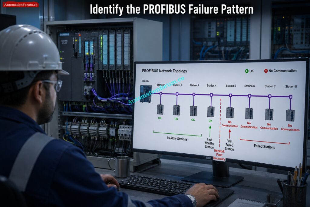
The distinction between these patterns is important. If one slave fails, investigate that device, its connector, address, power, and configuration. If several consecutive stations fail, suspect the cable section, connector, termination, or another common network problem.
Common Causes of PROFIBUS Communication Errors
Siemens documentation also shows that loss of connection and loss of data exchange can point engineers toward different checks, including the bus connection, cable, configuration, and PROFIBUS address.
Refer the below link for the Profibus Segment Calculator for DP and PA Network Design
How to Troubleshoot PROFIBUS Communication Failure
Step 1 Identify the PROFIBUS Failure Pattern
Before touching the network, determine exactly what has happened.
Ask:
- Is the complete PROFIBUS segment down?
- Are several consecutive stations affected?
- Is the problem permanent or intermittent?
- Did the network work correctly before?
- Did the fault appear after maintenance?
- Was a connector removed?
- Was a new device installed?
- Does the problem appear when a motor or variable speed drive starts?
This simple observation can save considerable troubleshooting time.
Step 2 Check PLC and PROFIBUS Master & Slave Diagnostics
- Start with the information already available in the control system.
- PLC diagnostic buffer Check PROFIBUS master diagnostics Slave diagnostics Communication status Station availability Configuration messages Parameterization messages Timeout information
- Do not treat a BF or SF indication as the reason. It is usually an indication that further diagnosis is required. Siemens devices can provide additional diagnostic information through the engineering system and device status indications.
- The objective is to determine whether communication never started, configuration was rejected, or an established connection was later lost.
Strengthen Industrial Networks Against Today’s Cybersecurity Threats: Top Companies in Industrial Cyber Security: Best OT Security Vendors for Industrial Automation
Step 3 Inspect PROFIBUS Cable and Connectors
- Physical inspection should be performed carefully.
- Verify loose connectors, broken connector bodies, bad conductor connections, wrong A and B connections, damaged insulation, crushed cable, overbending, corrosion, and poor shield contact.
- Pay particular attention to the connector near the first failed station and the section between the last healthy station and the first failed station.
- A connector can appear normal externally while having a poor internal connection. PROFIBUS installation guidance specifically recommends checking connector seating, fastening, pins, cable assembly, and termination switch settings.
- Intermittent faults are especially suspicious when the problem changes after vibration, maintenance activity, or movement of the cable.
Decode Modbus Registers Without Making Costly Configuration Errors: Understanding the Four Types of Registers in Modbus Protocol
Step 4 Check PROFIBUS Termination
- Termination is one of the first physical layer checks to make.
- Each copper PROFIBUS segment requires proper termination at its two physical ends. An intermediate connector should not normally have its termination enabled. The termination arrangement must also remain valid for the actual operating condition of the segment.
- Check:
- Is termination enabled at both segment ends?
- Is termination accidentally enabled at an intermediate station?
- Is a required termination missing?
- Is the terminating device correctly powered?
- Has a connector been replaced with a unit having a different switch position?
- Incorrect termination can produce reflections and unstable communication. This often appears as intermittent errors rather than a simple permanent failure.
- Repeaters and separate segments must be checked according to the actual network architecture.
Verify Intrinsic Safety Parameters Before Connecting Hazardous Loops: Intrinsic Safety Entity Parameter Calculator for Reliable Hazardous Area Loop Design
Step 5 Verify PROFIBUS Station Address
- Every station must have the correct unique address.
- Compare the device physical address matches the set address in PLC engineering system.
- Check particularly after device replacement or commissioning changes. A replacement device may have a default address or an address different from the original unit.
- Do not assume the address is correct simply because the device was recently replaced.
Verify HART Loops Before Communication Problems Cause Downtime: Advanced HART Loop Calculator for Reliable 4 to 20 mA and HART Communication
Step 6 Check GSD File and PROFIBUS Configuration
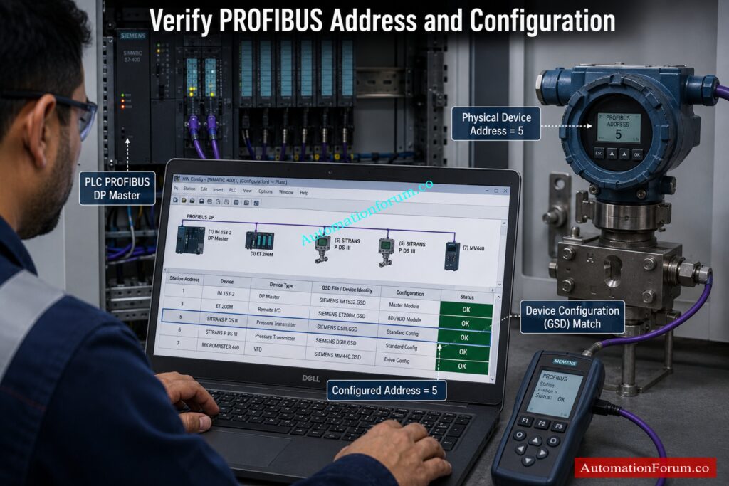
- Once the physical network looks healthy, review the configuration.
- Check the device type, hardware revision, selected modules, input and output data configuration, parameterization, and the GSD file used by the engineering system.
- A device can be physically healthy and still refuse communication because its configured identity or module arrangement does not match the actual device.
- For example, suppose an older drive is replaced with a newer revision. The connector may be correctly wired and the address may be correct, but the configured device information may not match the replacement. The result can be a configuration or parameterization fault.
Step 7 Check PROFIBUS Baud Rate and Communication Parameters
- Verify the communication parameters using the engineering configuration and manufacturer documentation.
- Check the configured baud rate, device compatibility, communication settings, and parameters applied after device replacement.
- Avoid changing communication settings randomly. One change at a time makes troubleshooting much easier because you can identify which modification affected the result.
- Some PROFIBUS diagnostic information can also include the baud rate and station status, providing useful evidence during investigation.
Understand Why ControlNet Requires Precise Network Termination: Why 75 Ohm Termination Resistor is Used in ControlNet?
Step 8 Check Slave Power Supply and Device Health
- A communication failure can actually be a power problem.
- Measure and verify the supply to the affected slave, communication module, and associated equipment. Look for loose power terminals, unstable voltage, supply interruption, repeated device restart, hardware initialization problems, and internal device faults.
- Observe the device status indications during the failure. If the device repeatedly restarts, the PROFIBUS communication failure may simply be the consequence of unstable device power.
- This is particularly important for remote I/O stations and drives where control power and communication electronics may have separate supply arrangements.
Step 9 Check PROFIBUS Shielding, Grounding and Electrical Noise

- Industrial electrical equipment can create conditions that disturb communication.
- Investigate the area around variable speed drives, large motors, contactors, switching equipment, and high current power cables.
- Check shield continuity, cable routing, grounding connections, and potential equalization according to the network design and plant earthing philosophy. There is no single grounding arrangement that should be applied blindly to every installation.
- If communication becomes unstable only when a large motor or drive starts, investigate electromagnetic interference and signal quality rather than immediately replacing the slave.
Calculate Barrier Earth Fault Current Before Commissioning: IS Barrier Earth Fault Current Calculator | Intrinsic Safety Loop Design Tool
Step 10 Isolate the PROFIBUS Network Fault
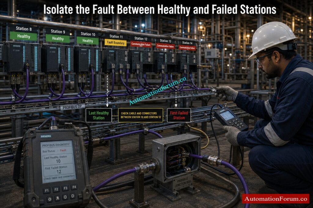
- For a large network, identify the last station that communicates correctly and the first station that fails.
- Then investigate the section between them.
- Check the cable, the connectors, the termination, the local power supply and the affected slave.
- This cuts the search area down substantially. You don’t examine the complete PROFIBUS network, but you look at the physical and logical boundary between healthy and failing communication.
Step 11 Use PROFIBUS Diagnostic Tools
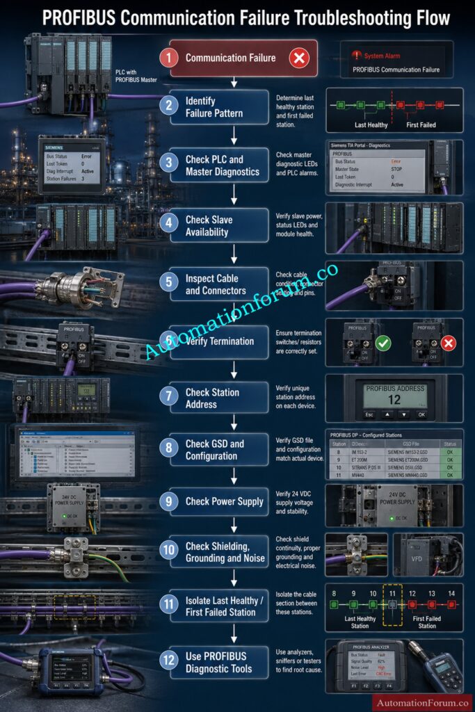
- If the fault cannot be identified using the PLC diagnostics and visual inspection, utilize a dedicated PROFIBUS diagnostic tool or adequate measuring equipment.
- Advanced diagnostics can be used to assess signal quality, voltage, noise, reflections, telegram mistakes, retries, station availability, topology and cable condition.
- Troubleshooting approaches which are helpful according to PROFIBUS commissioning recommendations are: Bus monitoring, analysis of diagnostic telegrams, oscilloscope measurements and inspections on the cable infrastructure.
- These tools are particularly valuable for intermittent faults that disappear before a technician reaches the affected station.
Restore Remote IO Communication With Proven Troubleshooting Techniques: PLC Troubleshooting Remote IO Rack Communication Failure Complete Troubleshooting Guide for Industrial Automation Engineers
Common PROFIBUS Communication Failures and Their Causes
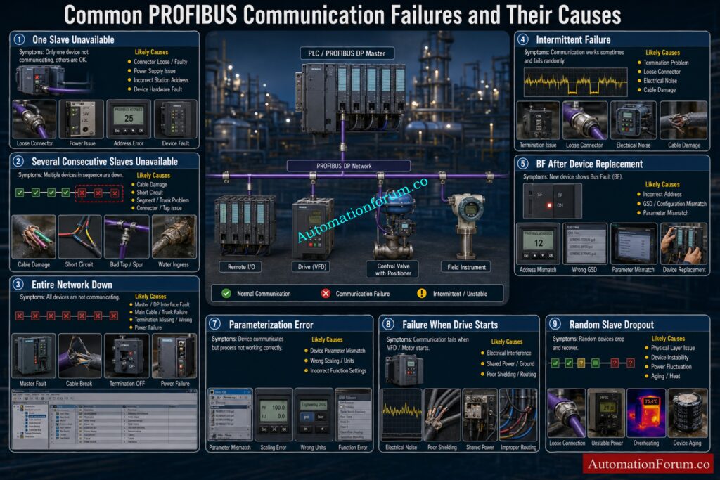
| Symptom | Likely Cause | How to Check | Recommended Action |
| One slave unavailable | Connector, power, address, device fault | Check local device and diagnostics | Repair or replace the confirmed fault |
| Several consecutive slaves unavailable | Cable or segment problem | Find last healthy and first failed station | Inspect the section between them |
| Entire network down | Master, cable, termination, or power problem | Check master diagnostics and segment condition | Isolate the network fault |
| Intermittent failure | Termination, connector, noise, cable damage | Monitor when fault occurs | Check signal quality and physical layer |
| BF after device replacement | Address or configuration mismatch | Compare device and PLC configuration | Correct address or configuration |
| Configuration error | GSD or module mismatch | Compare actual and configured device | Correct engineering configuration |
| Parameterization error | Device parameter mismatch | Review diagnostic information | Correct parameters |
| Failure when drive starts | Electrical interference | Observe timing with drive operation | Investigate routing, shielding, grounding, and signal quality |
| Random slave dropout | Physical layer or device instability | Check retries and signal quality | Isolate the affected section |
Refer the below link for the Fieldbus Intrinsically Safe Concept (FISCO) Model for Foundation Fieldbus H1 and Profibus PA
What Is the Working Principle of PROFIBUS?
PROFIBUS uses a structured communication system in which a master communicates with configured field devices. The exchange of process data is controlled by the master and the linked devices offer their measured values, status information and diagnostic information.
How PROFIBUS Master and Slave Communication Works
The PROFIBUS master handles the communication with the configured slave devices on the network. Each slave has a unique station address so the master can identify the correct device and exchange data with it .
Under typical circumstances, the master communicates with the configured stations based on the network setup. If a slave does not react appropriately, the master can diagnose the communication problem and report diagnostics across the control system.
Choose The Right Isolation Method For Hazardous Loops: Understanding Zener vs Galvanic Isolation in IS Loops for 4 to 20 mA Systems
How PROFIBUS Exchanges Process Data
PROFIBUS enables field devices such as remote I O stations, drives, valves and process instruments to communicate process information to the control system.
The master gets input information from the field devices and sends output information to the devices concerned. This is a continual interchange that allows the PLC or control system to monitor and control the industrial process.
How PROFIBUS Diagnostic Data Is Used
During troubleshooting, diagnostic information should be reviewed before replacing hardware because it can help distinguish a network problem from a device or configuration problem.
Stop PROFIBUS PA Failures Before They Escalate: Profibus PA Communication Problems: Causes, Symptoms and Troubleshooting Guide
How to Check PROFIBUS Communication
Checking PROFIBUS communication should begin with the control system diagnostics and then move toward the physical network. This method allows to discover if the problem is affecting the full network, a set of stations or only one slave.
Check PROFIBUS Master Communication Status
1. Check the state of the PROFIBUS master in the PLC engineering system first. Check bus failure indications, station availability, communication status, diagnostic messages and time out information.
If numerous stations are down, check their position in the network to see if they are on the same cable section or network component.
Check PROFIBUS Slave Availability
If several consecutive slaves disappear, investigate the network section between the last healthy station and the first failed station.
Check PLC Diagnostic Messages
Before changing equipment, check the PLC diagnostic buffer and PROFIBUS master diagnostics. Loss of communication . Configuration errors . Parameter faults . Station errors . Repeated timeouts in communication .
These messages could be a good starting point to find out if the problem is the communication, configuration or the field device.
Check PROFIBUS Cable and Connectors
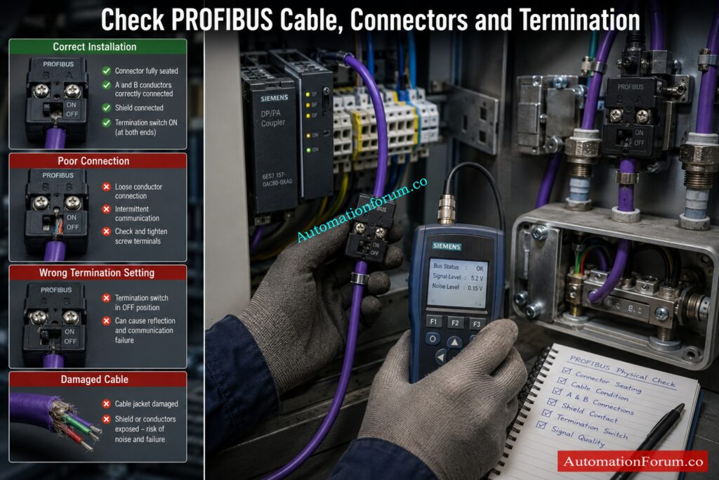
Check the cable and connectors around the afflicted station and the boundary between healthy and failing stations. Check for loose connectors, damaged cable, poor conductor connections, incorrect A and B connections, corrosion, and poor shield contact.
Intermittent faults require particular attention because vibration, maintenance activity, or cable movement can temporarily change the communication condition.
Check PROFIBUS Termination and Signal Quality
Verify that termination is correctly applied at the physical ends of the PROFIBUS segment and that an intermediate station does not have termination enabled incorrectly. Also check the condition and power arrangement of the terminating connections.
If the problem remains intermittent, use suitable PROFIBUS diagnostic equipment to investigate signal quality, reflections, noise, telegram errors, and communication retries.
PROFIBUS vs PROFINET: Discover Which Network Wins: PROFIBUS vs PROFINET: Complete Industrial Network Comparison
PROFIBUS Communication Failure Troubleshooting Checklist
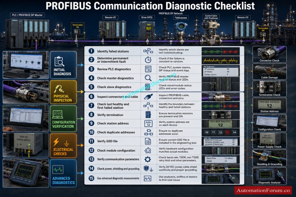
- Identify exactly which stations have failed.
- Determine whether the fault is permanent or intermittent.
- Review PLC and master diagnostic information.
- Check the failed slave diagnostic information.
- Inspect connectors and PROFIBUS cable.
- Check the section between the last healthy and first failed station.
- Verify termination at the actual segment ends.
- Check the physical station address.
- Check for duplicate addresses.
- Verify the configured device and GSD file.
- Check module and parameter configuration.
- Verify communication parameters.
- Check slave power supply and device health.
- Investigate shielding, grounding, and electrical noise.
- Use advanced diagnostic measurements when the fault remains unresolved.
Test Your PROFIBUS Knowledge With These Expert Questions: PROFIBUS Quiz: Top 25 Advanced Interview MCQs with Answers for Automation Professionals
Common PROFIBUS Troubleshooting Mistakes
The most common mistake is replacing hardware before understanding the diagnostic evidence.
Other mistakes include changing several parameters at once, ignoring the PLC diagnostic buffer, assuming every fault is a cable problem, overlooking termination, ignoring duplicate addresses, using an incorrect GSD file, checking only the failed slave, and failing to inspect the network section before the failed station.
Another common mistake is changing communication settings without a clear reason. A systematic diagnosis is normally faster and creates less risk than trial and error.
Prepare Smarter With These Critical PROFIBUS Interview Questions: Profibus Interview Questions and Answers
Frequently Asked Questions About PROFIBUS Communication
How to check PROFIBUS communication?
Check the PLC diagnostics, master status, slave availability, connectors, cable, termination, and station addresses.
For difficult faults, use PROFIBUS diagnostic tools to check signal quality, noise, reflections, and telegram errors.
What is the working principle of PROFIBUS?
PROFIBUS uses a master and slave communication method where the master controls communication with configured field devices.
The master exchanges process data with slaves while diagnostic information helps identify communication and device problems.
How to reset PROFIBUS?
See the Critical Differences Between Two Fieldbus Technologies: Difference between profibus and foundation field bus
What is DP and PA in PROFIBUS?
PROFIBUS DP is mainly used for fast communication with remote I O, drives, PLCs, and automation devices.
PROFIBUS PA is designed mainly for process instrumentation and can provide communication and power through the field network.
Which cable is used for PROFIBUS?
PROFIBUS DP usually use a PROFIBUS communication-specific shielded twisted pair cable.
The selection of cable depends with the transmission speed, installation environment, network design and segment length requirement.
What is PROFINET speed?
100 Mbps is the usual speed for PROFINET in industrial Ethernet deployments.
The Ethernet technology and capabilities of the connected devices can support higher connection speeds.
What provides PROFIBUS communication?
The PROFIBUS master initiates the communication for the exchange of data with the preset field devices.
Slave devices send process data, status information and diagnostic information to the master.
What causes intermittent PROFIBUS communication failure?
Typical causes are bad connectors, damaged cable, improper termination, electrical interference, shielding difficulties, and unstable power.
Physical layer issues may be difficult to spot visually and signal quality measures can help to validate this.
How do I troubleshoot a PROFIBUS termination problem?
Ensure that termination is enabled only at the extreme ends of each PROFIBUS segment.
Also check termination power, connection condition, cable continuity and actual network layout.
Why does one PROFIBUS slave keep disappearing?
First verify the local connector, cable, power supply, station address, setup and device diagnostics.
Discover How PROFIBUS Transforms Modern Instrumentation Applications: What is Profibus and what is its application in Instrumentation?
Conclusion: PROFIBUS Communication Failure
Understanding the failure pattern is the starting point of diagnosing any breakdown and not instant replacement of equipment.
First, check the diagnostics. Check the physical network, connectors, termination, addresses, configuration, GSD information, power supply, shielding, grounding and electrical noise.
Finally, isolate the affected network section and use advanced diagnostic tools when necessary.
The key is to distinguish between a physical layer fault, configuration problem, and device problem. Once that distinction is made, even a difficult PROFIBUS bus fault becomes much easier to locate and correct.
Refer the below link for the PLC Input ON but Output Not Energizing: Complete Troubleshooting Guide
