- What is a Termination Resistor in ControlNet?
- Where are ControlNet Terminators Installed?
- ControlNet Trunk Cable Termination Points
- End of Line Termination in ControlNet Networks
- Common Locations for ControlNet Terminators
- Characteristic Impedance of RG 6 Coaxial Cable
- Understanding Impedance Matching in ControlNet
- Relationship Between Cable Impedance and Termination Resistance
- Why Impedance Matching is Critical for Signal Integrity
- Understanding Impedance Matching in Industrial Communication Networks
- Why ControlNet Uses RG 6 Quad Shield Cable
- Why 50 Ohm Resistors are Wrong for ControlNet
- Why 120 Ohm Resistors are Wrong for ControlNet
- How Signal Reflection Happens in an Unterminated ControlNet Network
- Problems Caused by Signal Reflection in ControlNet
- Real Industrial Symptoms of Missing ControlNet Terminators
- What Happens if the 75 Ohm Terminator is Missing?
- Correct Method to Install ControlNet 75 Ohm Termination Resistors
- Common ControlNet Installation Mistakes
- Best Practices for Reliable ControlNet Installation
- Difference Between ControlNet, Ethernet, DeviceNet, and CAN Bus Termination
- Common ControlNet Termination Mistakes Engineers Make
- How to Troubleshoot ControlNet Termination Problems
- How to Measure ControlNet Termination Resistance
- Frequently Asked Questions About ControlNet 75 Ohm Terminators
- Can ControlNet Work Without a Termination Resistor?
- Why are Two Terminators Required in ControlNet?
- What Happens if the Wrong Resistor Value is Used?
- Why is ControlNet Cable 75 Ohm?
- Can Normal BNC Terminators be Used in ControlNet?
- How do You Test ControlNet Termination?
- What Resistance Should be Measured Across the Trunk?
- Why Does ControlNet Require Impedance Matching?
- What Cable Does ControlNet Use?
- What are Common Symptoms of Missing Terminators?
- Conclusion: Importance of 75 Ohm Termination in ControlNet Networks
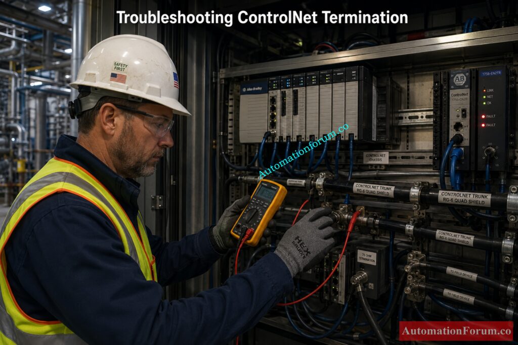
One of the most critical things that modern automation systems need is reliable industrial connectivity. PLCs, remote I O racks, HMIs, drives, analyzers, and process controllers that need deterministic communication to work properly can all be part of a ControlNet network. Even if the PLC program and hardware are right, bad cable termination might cause big problems with communication. This is why the ControlNet 75 Ohm Termination Resistor is so vital. It stops signal reflections, keeps impedance matching, protects signal integrity, and helps the network run consistently in industrial settings where there is a lot of electrical noise.
What is a Termination Resistor in ControlNet?
Purpose of a ControlNet Termination Resistor
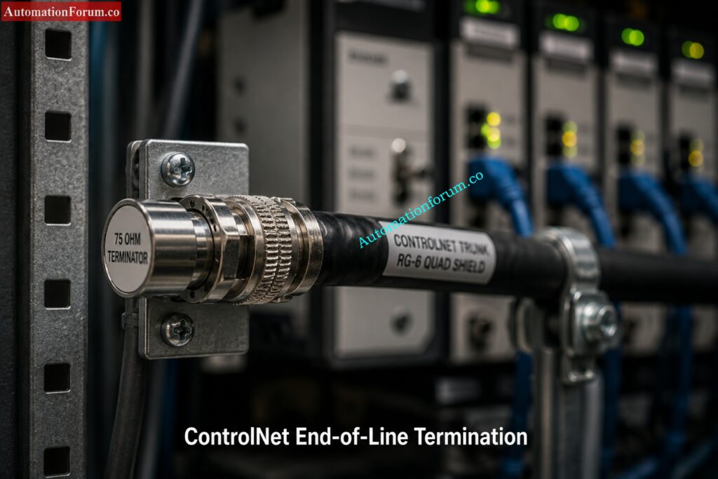
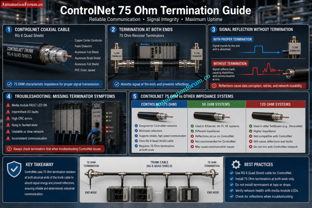
A ControlNet termination resistor is a specially designed 75 ohm resistor installed at both physical ends of the ControlNet trunk cable.
Its main purpose is to absorb the communication signal when it reaches the cable end so the signal does not reflect back into the network.
How a 75 Ohm Terminator Works in ControlNet
In ControlNet systems, the communication signal travels through RG 6 quad shield coaxial cable at high speed. If the cable end is left open, the signal energy reflects back toward the source and interferes with incoming communication.
The termination resistor works like a signal absorber.
Why Signal Reflection Happens Without Termination
Without proper termination:
- Reflections of signals go up
- There are retries in communication
- There seems to be packet corruption.
- Node synchronization gets unstable
- The scheduled data transmission might not work.
- Communication problems happen at random more often
Benefits of Proper ControlNet Termination
With proper termination:
- The signal energy is absorbed accurately.
- Communication gets steady
- The quality of the signal gets better.
- Deterministic network scheduling works as it should, and PLC and remote I/O connectivity stays reliable.
Rockwell Automation says that each ControlNet coaxial section must include 75 ohm termination resistors at both ends.
Refer the below link for the Profibus Segment Calculator for DP and PA Network Design
Where are ControlNet Terminators Installed?
ControlNet Trunk Cable Termination Points
ControlNet terminators are installed at the two physical ends of the trunk cable using BNC connectors. Their job is to absorb the communication signal at the cable end and prevent reflections from returning into the network.
End of Line Termination in ControlNet Networks
Proper termination is required at both ends of the ControlNet trunk. This helps make the network stable and predictable, as well as maintain the integrity of the signals and lower the number of communication failures.
Common Locations for ControlNet Terminators
Typical terminator installation points include the following:
- Main PLC rack end
- Final remote I/O rack
- Fiber repeater segment ends
- Last tap on the trunk cable
- Redundant media segment ends
Both ends of the trunk cable must always be terminated correctly.
Why Exactly 75 Ohm Resistor is Used in ControlNet?
This is one of the most important concepts in ControlNet network engineering.
The answer comes directly from transmission line theory and impedance matching principles.
Characteristic Impedance of RG 6 Coaxial Cable
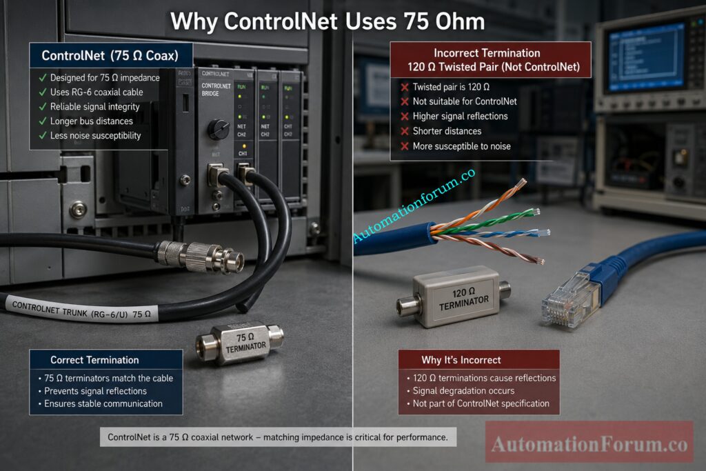
ControlNet uses RG 6 quad shield coaxial cable as the physical communication medium.
The impedance of RG 6 cable is 75 ohms.
The termination resistor must also be 75 ohms because the cable impedance is 75 ohms.
The impedance of the termination must be the same as the impedance of the cable:
Understanding Impedance Matching in ControlNet
Z (termination) = Z (cable) = 75 Ω
Relationship Between Cable Impedance and Termination Resistance
When both values are correct:
- Reflections of signals are kept to a minimum.
- The energy of the signal is absorbed correctly.
- Standing waves are not allowed.
- Communication stays the same
Why Impedance Matching is Critical for Signal Integrity
If the values are not the same:
- Signal energy reflects back
- Communication errors increase
- Noise sensitivity becomes worse
- Packet corruption occurs
- Network instability appears
Understanding Impedance Matching in Industrial Communication Networks
Transmission Line Theory in ControlNet
Impedance matching is an important part of how industrial communication systems work. When the communication speed is high, the cable doesn’t act like a basic wire anymore; it acts like a transmission line, and if the termination isn’t right, the signal can bounce back.
Reflection Coefficient Formula Explained
Every transmission line has an impedance that is unique to it. The signal is correctly absorbed when it reaches a load that matches the cable’s impedance. If the impedance doesn’t match, some of the signal goes back into the network.
The reflection coefficient is:
Γ = (ZL – Z0) / (ZL + Z0)
Where:
- ZL = load impedance
- Z0 = cable impedance
How Matching Impedance Eliminates Signal Reflection
The reflection coefficient becomes: when both impedances are equal.
Γ = 0
This implies that signals don’t bounce back, which makes the network run better and with fewer mistakes.
Standing Waves and Communication Stability
If the impedance doesn’t match, reflections can cause standing waves, signal distortion, retries, and communication that isn’t steady. Matching the impedance correctly keeps the signal clean and the ControlNet performance stable.
PLC Cybersecurity Mistakes That Can Destroy Your Plant: How to Safeguard PLCs Against Cyber Attacks in Industrial Networks ?
Why ControlNet Uses RG 6 Quad Shield Cable
Advantages of RG 6 Quad Shield Cable
- ControlNet is built for tough industrial settings where electrical noise is widespread.
- It is commonly put next to variable frequency drives, high-current motors, welding machines, big power lines, switching devices, and other things that can cause electromagnetic interference.
- This area is good for RG 6 quad shield cable since it has excellent shielding and reliable communication.
EMI Protection in Industrial Automation Networks
- The quad shield design keeps electromagnetic interference from getting to the transmission.
- This is especially crucial in plants where there is a lot of noise and electrical problems can make it hard to talk to each other.
- Better shielding makes things more reliable and cuts down on data mistakes.
Noise Immunity in ControlNet Communication
- RG 6 quad shield cable makes noise immunity better by making it less likely that outside electrical noise will affect it.
- This lets ControlNet keep communication reliable and predictable.
- It helps the network run well even when there are big machines nearby.
Signal Integrity Benefits of Quad Shield Cable
- The RG 6 quad shield cable helps keep the signal clear over the whole network.
- It reduces signal attenuation and supports longer communication distances.
- Belden and Rockwell documentation identify RG 6 quad shield cable as the standard media for ControlNet systems.
Foundation Fieldbus MCQs That Challenge Senior Engineers: Foundation Fieldbus Network Protocol: Top 25 Advanced MCQ
Why 50 Ohm Resistors are Wrong for ControlNet
Difference Between ControlNet and Ethernet Coaxial Networks
- Many technicians mistakenly compare ControlNet with older Ethernet coaxial systems.
- Older Ethernet networks commonly used:
- RG 58 coaxial cable
- 50 ohm cable impedance
- 50 ohm termination resistors
- ControlNet is different because it uses RG 6 quad shield coaxial cable with a characteristic impedance of 75 ohms.
Problems Caused by 50 Ohm Terminators
- Using a 50 ohm resistor in a ControlNet network creates improper termination.
- The resistor value no longer matches the cable impedance.
- This mismatch might make communication over the network and signal quality worse.
Impedance Mismatch Effects in ControlNet
ControlNet can have problems when you utilize 50 ohm terminators:
- Signal reflection
- CRC communication errors
- Communication retries
- Random node dropouts
- Unstable network operation
- Increased noise sensitivity
- Reduced communication reliability
Modbus Baud Rate Errors Causing Serious Communication Failures: Key Factors to Consider When Setting Baud Rate in Modbus Networks
Why 120 Ohm Resistors are Wrong for ControlNet
Networks That Use 120 Ohm Termination
Common networks that use 120 ohm resistors are:
- CAN Bus
- DeviceNet
- RS-485
- Profibus
Difference Between Twisted Pair and Coaxial Cable Networks
- These networks use twisted pair cable, not RG 6 coaxial cable.
- Since the cable type is different, the characteristic impedance is also different.
- That is why the termination resistor value must also be different.
Why DeviceNet and CAN Bus Use 120 Ohm Resistors
- DeviceNet and CAN Bus are designed around twisted pair transmission lines.
- Their termination must match the cable impedance to prevent reflections and communication problems.
- A 120 ohm resistor is correct for those systems, but it is not correct for ControlNet.
DeviceNet Interview Questions That Instantly Test Your Skills: Mastering DeviceNet Industrial network protocol: Top Interview Questions and Answers
How Signal Reflection Happens in an Unterminated ControlNet Network
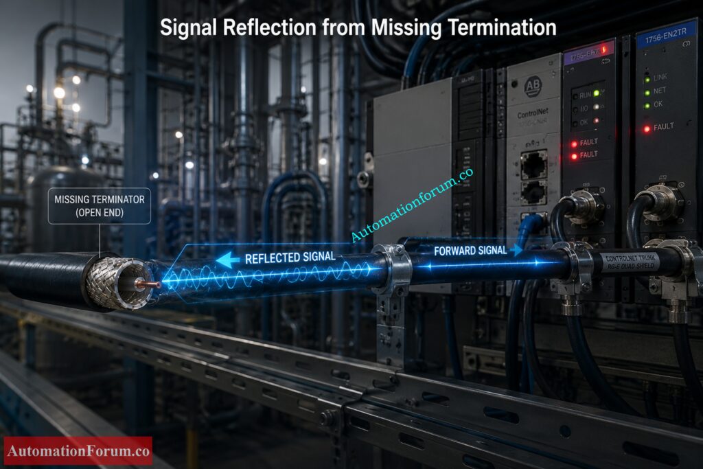
Signal Propagation Inside Coaxial Cable
- Understanding signal reflection is important for troubleshooting ControlNet communication problems.
- Electromagnetic waves carry communication signals through the coaxial cable.
- When the signal gets to the end of the cable:
- The signal is absorbed by the right termination.
- If termination is missing, the signal goes back into the network.
- The reflected signal messes up incoming communication and makes the network unstable.
Echo Effect Analogy for Signal Reflection
- You can think of signal reflection as yelling in a tunnel.
- The sound wave goes to the end of the tube and then comes back.
- When the cable isn’t correctly terminated, ControlNet reflections act in a similar way.
Water Pipe Analogy for Understanding Reflections
- Imagine water flowing through a pipe and suddenly hitting a closed end.
- The pressure wave bounces backward through the pipe.
- Communication signals inside a ControlNet cable behave similarly when termination is missing.
How Reflections Disturb Deterministic Communication
- Reflected signals interfere with normal communication timing.
- This has an effect on predictable data transfer and makes the network less stable overall.
- Reflections can cause problems with communication and make networks less dependable over time.
SCADA and DCS Switch Requirements Most Engineers Ignore: Network Switches requirements in “SCADA” and “DCS” Architecture
Problems Caused by Signal Reflection in ControlNet
Packet Corruption and Communication Retries
Signal reflection can cause:
- Packet corruption
- Communication retries
- Retransmissions
- Delayed communication
Node Synchronization Problems
- This has an effect on predictable data transfer and makes the network less stable overall.
- Reflections can cause problems with communication and make networks less dependable over time.
Scheduled Data Transfer Failure
- ControlNet depends on deterministic scheduled communication.
- Signal reflections can interrupt scheduled data exchange and create timeout conditions.
- This could make PLC and remote I/O communication unstable.
Increased Network Jitter and Signal Distortion
Reflections can also cause other problems, such as:
- Increased network jitter
- Signal distortion
- Standing waves
- Reduced signal integrity
- Unstable communication performance
Industrial Network Equipment Every Smart Engineer Must Understand: Network Equipment listNetwork Equipment: Types, List, Management, Classification & Best Practices
Real Industrial Symptoms of Missing ControlNet Terminators
Random PLC Communication Loss
- Plants may have random PLC communication problems if they don’t have the right terminators or if they are missing.
- These problems are often sporadic and hard to figure out.
Intermittent Remote I/O Rack Failure
- Remote I/O racks may disconnect unexpectedly.
- Communication can appear normal for some time and then suddenly fail.
HMI Communication Interruption
- Network signals that aren’t reliable can make HMIs lose communication from time to time.
- Operators may detect that updates are late or that communication timeouts are going off.
Flashing Red Network LEDs
- ControlNet modules could have flashing red LEDs or media fault indicators.
- These warnings are common signs of communication instability caused by reflections.
ControlNet Node Dropouts and Media Faults
Additional industrial symptoms may include:
- Scheduled connection timeout
- Media redundancy faults
- Random node dropouts
- Intermittent network failures
- Network LEDs turning red unexpectedly
- In many cases, the actual root cause is simply one missing 75 ohm termination resistor.
Switch Port Allocation Mistakes Killing Industrial Network Performance: Network switch port allocation details
What Happens if the 75 Ohm Terminator is Missing?
Communication Instability in ControlNet
- A missing terminator can create serious communication instability in a ControlNet network.
- When the trunk cable is not properly terminated, signal reflections return into the network and disturb normal data transfer.
Scheduled Connection Failure
- ControlNet depends on deterministic scheduled communication.
- If reflections interfere with timing, the network may experience:
- PLC scan delays
- I/O timeout errors
- Node synchronization faults
Intermittent Industrial Network Faults
- One of the hardest problems to diagnose is intermittent failure.
- The system may run normally for hours and then fail suddenly.
- These faults often become worse during:
- Motor startup
- Electrical noise events
- Heavy network traffic
- VFD operation
Real Plant Example of Missing Terminator Failure
- In one refinery, random evening ControlNet failures led technicians to replace PLC modules, remote I/O adapters, and communication cards.
- The real cause was a missing 75 ohm terminator that had been removed during maintenance.
- Once the terminator was reinstalled, the network became stable immediately.
Industrial Automation Network Levels Explained Like Never Before: Various Network Levels in Industrial Automation
Correct Method to Install ControlNet 75 Ohm Termination Resistors
Correct Installation Rules for ControlNet Terminators
- Install one terminator at each physical end of the trunk cable.
- Never install a terminator in the middle of the trunk.
- Use approved ControlNet taps and proper BNC connectors.
- Maintain the correct trunk topology.
- Verify shielding continuity during installation.
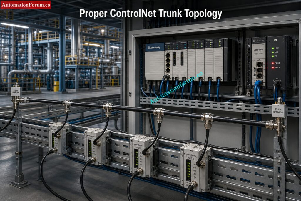
Proper ControlNet Trunk Topology
- A standard ControlNet network includes:
- One trunk cable
- Multiple taps
- Two end terminators
- Both ends of the trunk must always be terminated correctly.
Approved ControlNet Taps and BNC Connectors
- ControlNet taps that have been approved are made to keep the impedance across the network the same.
- Using third-party connectors or the wrong hardware might cause impedance discontinuities and make reflections worse.
Importance of Shielding Continuity
- Proper shielding helps protect the network from electrical noise.
- Shielding continuity is essential for maintaining stable communication in industrial environments.
Remote I O Explained for Faster PLC Troubleshooting: Understanding Remote I/O in PLC Control Systems
Common ControlNet Installation Mistakes
Missing or Extra Terminators
- One common reason for network instability is forgetting a terminator.
- Adding more than two terminators might make the signal load heavier and slow down performance.
Wrong Resistor Values in ControlNet
- Using resistors with 50 or 120 ohms generates an impedance mismatch.
- This can cause reflections, communication problems, and unstable functioning.
Incorrect Cable Type Usage
- If you use RG 58 or RG 59 instead of RG 6, you can have problems with termination and impedance.
- ControlNet is made for RG 6 quad shield coaxial cable.
Poor Connector Crimping Problems
- Connectors that are loose or not crimped properly can cause problems with the signal and make it work only sometimes.
Improper Trunk Branching and Topology Errors
- Reflections and signal loss might happen if the network layout is wrong or the branching is wrong.
- For ControlNet communication to work, the trunk structure needs to be clean.
Fieldbus Technology Explained for Modern Process Industries: What is Fieldbus?
Best Practices for Reliable ControlNet Installation
ControlNet Installation Checklist
- Verify RG 6 quad shield cable
- Confirm 75 ohm terminators
- Install only two terminators
- Inspect BNC connector quality
- Avoid sharp cable bends
- Keep distance from power cables
- Use approved taps
- Verify shielding continuity
- Inspect grounding practices
- Test resistance before startup
Proper Cable Routing Practices
- Route ControlNet cables away from power conductors and noise sources.
- Avoid unnecessary bends, strain, and physical damage to the cable.
Grounding and Shielding Recommendations
- Proper grounding and shielding cut down on electrical noise and help keep signals stable.
- In tough industrial settings, good shielding is quite important.
Maintaining Signal Integrity in Industrial Environments
- Good installation methods help keep the signal quality high.
- This helps keep the network running smoothly and cuts down on communication mistakes.
Fieldbus vs HART: The Truth Engineers Need Today: Difference Between Fieldbus and HART Communication Protocols: Complete Comparison Guide for Process Automation Engineers
Difference Between ControlNet, Ethernet, DeviceNet, and CAN Bus Termination
| Network | Cable Type | Characteristic Impedance | Termination Resistor | Key Note |
| ControlNet | RG 6 coaxial cable | 75 ohm | 75 ohm | Matches the cable impedance for proper signal termination. |
| Ethernet 10Base2 | RG 58 coaxial cable | 50 ohm | 50 ohm | Uses a different coaxial cable and termination value. |
| CAN Bus | Twisted pair cable | 120 ohm | 120 ohm | Uses twisted pair wiring, so the termination value is different. |
| DeviceNet | Twisted pair cable | 120 ohm | 120 ohm | Termination must match the network’s cable impedance. |
Why Different Industrial Networks Use Different Resistor Values
- Different industrial networks use different resistor values because their transmission line impedance is not the same.
- The basic rule is always the same: the termination resistor must match the cable impedance.
Industrial Communication Protocols Driving Smart Factory Automation: Connecting the Industrial World: An Exploration of Communication Protocols in Automation and Instrumentation
Common ControlNet Termination Mistakes Engineers Make
Using Standard BNC Tees
- Standard BNC tees may not maintain the correct impedance characteristics for ControlNet.
- This can introduce reflections and instability.
Installing More Than Two Terminators
- More than two terminators increases loading on the network.
- This can reduce signal strength and create communication issues.
Using Incorrect Coaxial Cable Types
- Using the wrong cable type, such as RG 58 or RG 59, can create mismatched impedance and poor performance.
- ControlNet should use RG 6 quad shield cable.
Poor Shielding and Grounding Practices
- Weak shielding or poor grounding increases susceptibility to electrical noise.
- This can cause intermittent communication faults and unstable operation.
If you want, I can also convert this into a more SEO-friendly blog format with shorter bullet points and stronger subheadings.
CC Link Protocol Secrets Every Automation Engineer Should Know: CC-Link Industrial Network Protocol: Architecture, Variants, and Applications
How to Troubleshoot ControlNet Termination Problems
Visual Inspection of ControlNet NetworksWhere are ControlNet Terminators
- Check for missing terminators at both ends of the trunk cable.
- Inspect all connectors for looseness or poor contact.
- Look for damaged taps, broken shielding, corroded connectors, and cable cuts.
Measuring Resistance Across the Trunk Cable
- Turn the power OFF before testing.
- Measure resistance across the trunk cable to verify termination.
- A correctly terminated ControlNet network should read approximately 37.5 ohm.
Expected 37.5 Ohm Reading Explained
- Two 75 ohm terminators connected in parallel will measure about 37.5 ohm.
- This reading confirms that both end terminators are installed correctly.
Using ControlNet Diagnostic Tools
- Use Rockwell diagnostic tools such as:
- ControlNet Media Checker
- RSNetWorx diagnostics
- These tools help identify:
- Signal quality problems
- Cable faults
- Impedance mismatch
- Noise issues
LED Diagnostics for ControlNet Faults
- Observe module LEDs carefully.
- Common warning signs include:
- Flashing red network LED
- Media fault LED
- Communication fault LED
Oscilloscope Testing for Signal Reflection
- Advanced troubleshooting may use an oscilloscope.
- This helps check for:
- Reflections
- Waveform distortion
- Noise levels
- Standing waves
Modbus TCP/IP vs Profinet: Which One Dominates Industry: Modbus TCP/IP vs Profinet: Which Protocol Suits your Industrial Network Best?
How to Measure ControlNet Termination Resistance
Step by Step Resistance Measurement Procedure
- Power down the network.
- Measure resistance across the trunk cable.
- Compare the reading to what you expect, which is 37.5 ohm.
- Check that both terminators are there and in the right place.
Why Power Must Be OFF During Measurement
- You have to turn off the power before testing resistance to get reliable data.
- This also keeps test tools and equipment from getting broken.
Interpreting Different Resistance Readings
- 37.5 ohm: normal, both ends are there.
- 75 ohm: one terminator missing.
- Infinite resistance: both terminators missing.
- Very low resistance: short circuit or extra terminator.
Detecting Missing Terminators and Short Circuits
- A resistance check is one of the fastest ways to identify termination problems.
- It helps detect missing terminators, shorts, and incorrect network loading.
Industrial Communication Interview Questions That Companies Actually Ask: Industrial Communication Protocol Interview Questions and Answers
Frequently Asked Questions About ControlNet 75 Ohm Terminators
Can ControlNet Work Without a Termination Resistor?
It may operate for a short time, but the network becomes unstable and unreliable. Missing termination leads to reflections and communication faults.
Why are Two Terminators Required in ControlNet?
ControlNet trunk cable has two physical ends. Both ends must absorb signal energy to prevent reflections from returning into the network.
What Happens if the Wrong Resistor Value is Used?
A wrong resistor value creates impedance mismatch. This can cause reflections, retries, communication errors, and node instability.
Why is ControlNet Cable 75 Ohm?
ControlNet uses RG 6 coaxial cable. RG 6 has a characteristic impedance of 75 ohm, so the terminator must match that value.
Can Normal BNC Terminators be Used in ControlNet?
No. ControlNet requires approved 75 ohm terminators to maintain proper signal integrity.
How do You Test ControlNet Termination?
Measure resistance across the trunk cable with power off. A proper reading confirms that the two end terminators are installed correctly.
What Resistance Should be Measured Across the Trunk?
The expected reading is approximately 37.5 ohm. This is due to two 75 ohm terminators connected in parallel.
Why Does ControlNet Require Impedance Matching?
Impedance matching prevents signal reflections at the cable ends. It keeps communication deterministic, stable, and clean.
What Cable Does ControlNet Use?
ControlNet uses RG 6 quad shield coaxial cable. We chose this cable because it has a 75 ohm impedance and is quite resistant to noise.
What are Common Symptoms of Missing Terminators?
Common symptoms include:
- Red LEDs
- Node dropouts
- Communication retries
- Random faults
- Intermittent network failure
Conclusion: Importance of 75 Ohm Termination in ControlNet Networks
- The ControlNet communication system needs the 75 ohm termination resistor to work.
- It has the same 75 ohm impedance as RG 6 coaxial wire and prevents reflections.
How Proper Termination Improves Industrial Communication Reliability
- Correct termination makes the signal stronger.
- It cuts down on communication mistakes, stops standing waves, and makes sure that communication is predictable.
Final Recommendations for Reliable ControlNet Installation
- Use ControlNet parts that have been approved.
- Use the right steps when installing.
- Make sure the cables are routed correctly.
- Whenever there are problems with communication, troubleshoot termination in a methodical way.
Refer the below link for Why Every HART Loop Needs a 250 Ohm Resistor