- Why Ethernet-APL Matters for EPC Projects
- What is Ethernet-APL and 10BASE-T1L?
- Basics Every EPC Engineer Must Grasp
- Standards and Procurement Requirements
- Physical Layer and Cable Topology – Practical Engineering Rules
- Power Delivery and Port Class Engineering
- Intrinsic Safety Design Procedure (2-WISE Implementation)
- Hazardous Area Wiring Best Practices
- Device Selection and Interoperability Checks
- Installation, Commissioning, FAT and SAT Procedures
- Migration Strategies for Greenfield and Brownfield Projects
- Diagnostics, Maintenance and Troubleshooting Guide
- FOUNDATION/PROFIBUS vs Multi-Pair Ethernet vs Ethernet-APL Comparison
- Engineering Checklist and Project Handover Procedure
- Field Installation Checklist – Technician Quick Reference
- Three EPC Case Studies
- Frequently Asked Questions (FAQ) – Ethernet-APL for EPC Engineers
Why Ethernet-APL Matters for EPC Projects
Ethernet APL is the process industry adaptation of single pair Ethernet that carries data and in many cases device power on a single balanced pair while supporting intrinsic safety in classified zones. For EPC teams this means simpler wiring fewer marshalling points and native Ethernet connectivity at the device edge. This guide focuses on practical fundamentals design checks installation rules wiring best practice commissioning step lists migration patterns and troubleshooting notes you can apply on greenfield and brownfield projects.
What is Ethernet-APL and 10BASE-T1L?
Ethernet APL is a physical layer solution aimed at process industry needs rather than office LAN environments. It is built on a long reach single pair PHY often referenced as 10BASE T1L that supports 10 Mbit s throughput over a single balanced conductor pair. Key basic concepts expanded
Why 4-20 mA Is Still the Most Reliable Instrument Signal: Why 4-20 mA Current Signal is Preferred Over Voltage Signal in Instrumentation?
Basics Every EPC Engineer Must Grasp
Single-Pair Physical Layer Explained
Ethernet APL uses one balanced conductor pair per segment instead of two pairs or four pairs found in classic Ethernet. The single pair carries the PHY signal and in many configurations also supplies low voltage power to the device.
Data Rate, Long Reach and Suitability for Process Telemetry
The physical rate is 10 Mbit s which is sufficient for process telemetry diagnostics and asset management while enabling lower complexity cabling and improved reach relative to copper multipair Ethernet.
Two-Wire Power and APL Port Profiles
APL defines port power classes and profiles so a field switch port can supply a defined amount of power to attached devices. Designers must allocate port budgets and ensure device draws fall within declared limits.
Intrinsic Safety and the 2-WISE Concept
APL supports an intrinsic safety model where device and port entity parameters are declared and checked so the energy available in a circuit remains below ignition thresholds in a classified area. This is commonly referenced as the two wire IS concept or 2 WISE.
Why Intrinsic Safety Is Critical in Hazardous Areas: Why Choose Intrinsic Safety (IS) for Hazardous Area Instrumentation?
Trunk and Spur Topology Explained
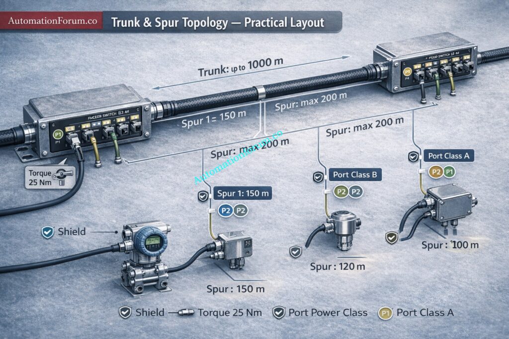
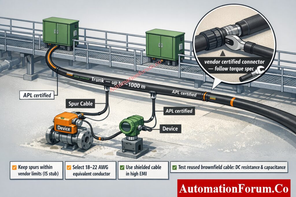
APL deployments commonly use trunk and spur topology. Trunks run between field switch locations while spurs branch to devices. The topology is familiar to fieldbus engineers and simplifies staged migration.
Vendors provide port profile data sheets entity parameter tables and zone certificates. Require these documents in procurement to avoid integration surprises.
Protocol Layer Independence and Application Use Cases
APL is a physical layer only. Any standard Ethernet based application protocol can run above it subject to device firmware support. Common use cases are device telemetry remote diagnostics and asset management.
How a Simple Modbus Address Mistake Shut Down an Entire Plant: Duplicate Modbus Address in Temperature Multiplexers Causes Plant Shutdown – Real Incident & Root Cause
Standards and Procurement Requirements
Specify compliance with core standards and guidelines in instrument and installation specs
- IEEE single pair PHY specification for the 10 Mbit s PHY
- IEC technical specification for two wire intrinsic safety for Ethernet often referred to as the 2 WISE framework
- APL port profile and engineering guideline documents that define port classes power classes and cable categories
- Device and field switch certificates for zone ratings and port conformance
Always require vendors to provide the port profile sheet entity parameters and zone certificate as part of the bid package.
Refer the below link for Why is a 250-Ohm Resistor Important for HART Communication?
Physical Layer and Cable Topology – Practical Engineering Rules
Trunk and Spur Architecture for Process Plants
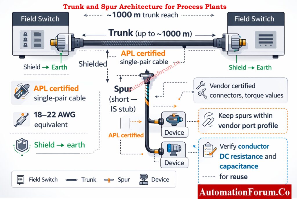
Trunk and spur remains the practical topology for most plant installations. Below is a compact ASCII diagram showing the concept using characters that do not include hyphen
Maximum Trunk Reach and Environmental Planning
Plan trunks for long reach capacity. Typical design targets use trunks up to around one thousand meters depending on cable category and ambient conditions. Use conservative design values based on cable data and site temperature.
Spur Length Limits and Intrinsic Safety Constraints
Spurs are shorter and in many IS schemes are treated as stubs with tighter limits. Keep spurs within recommended lengths from the port profile or vendor document to avoid violating entity parameter assumptions.
Cable Selection, Conductor Sizing and Voltage Drop Considerations
Specify APL certified single pair cable types and conductor sizes sized for mechanical durability and power drop. Conductor equivalents in the 18 to 22 AWG family are common but verify for your run lengths and ambient conditions.
Shielding, Jacket Selection and EMI Protection
Use shielded variants for high EMI environments and specify jacket chemistry and temperature rating for the process. Shield drain wiring must terminate to earth at the enclosure point chosen by the site earthing plan.
Common SCADA Communication Failures and Fixes: SCADA Communication Problems and How to Fix Them – A Complete Troubleshooting Guide
Connectors, Terminations and Torque Requirements
Use vendor certified APL rated connectors and follow termination torque values exactly. Use strain relief and ingress seals suitable for the zone and environmental rating.
Reusing Existing Fieldbus Cable in Brownfield Projects
Reuse is possible but only after verification of conductor gauge insulation capacitance and DC resistance against the port profile. Test each run and document acceptance.
Power Delivery and Port Class Engineering
APL enables power over the same pair in a controlled manner via port power classes. For EPC design follow these rules
Port Power Budget Calculation Method
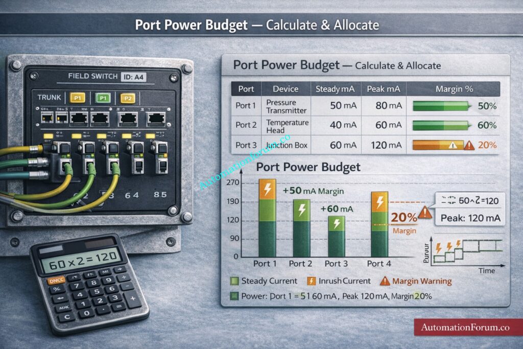
For every field switch maintain a power budget sheet that lists the available trunk power per switch and allocates per port. Include steady state draw and peak draw and keep a design margin typically twenty percent for growth and inrush.
Device Selection Criteria for Spur Powering
Small transmitters and smart sensors can be powered by APL spurs. Heavy devices such as motorized actuators and large valve positioners normally require local mains or local DC and must be excluded from spur powering unless explicitly supported by the port class.
Managing Inrush Current and Startup Sequencing
Account for device inrush currents at boot. Implement sequential connection of spurs during commissioning so multiple devices do not draw peak current simultaneously and trigger power limiting.
APL Junction Boxes and Local Distribution Strategies
Where multiple devices cluster use APL powered junction boxes or small distribution enclosures that report into the port profile while providing local terminations.
Fieldbus vs HART: Which Communication Method Is Better?: Difference Between Fieldbus and HART Communication Protocols: Complete Comparison Guide for Process Automation Engineers
Intrinsic Safety Design Procedure (2-WISE Implementation)
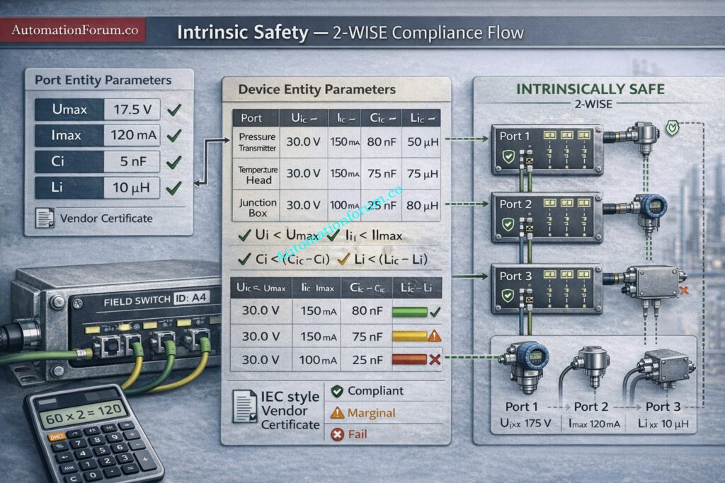
To implement the two wire IS model on projects follow these repeatable steps
- Define port class and power class per segment in the instrument specification.
- Require vendor entity parameters U max I max Ci Li and declared power for each device.
- Compare vendor entity values with port parameters to prove compliance.
- Design surge protection and earthing so protective devices do not invalidate the IS proof.
- Record IS mapping on schematic drawings and include the mapping in FAT and SAT deliverables.
Maintain an IS calculation workbook that traces each port to its attached devices and shows margin compliance.
Why Twisted Pair Cable Is Critical for 4–20 mA and RS-485 Signals: Twisted Pair Cable in Industrial Signal Transmission: The Essential Guide for 4-20 mA and RS 485 Systems
Hazardous Area Wiring Best Practices
Apply tried and true wiring rules adapted for APL
Equipotential Bonding and Shield Termination Strategy
Establish equipotential bonding for field enclosures and terminate shields as defined by the site earthing plan. Don’t use floating shields that let EMI in.
Routing Separation from Power Cables
Don’t let APL trunks touch power lines. To cut down on inductive and capacitive coupling, use different trays or pathways.
Surge Protection Device Placement for APL Networks
Put surge protecting devices that work with APL at marshalling and switch sites, but make sure that the SPD characteristics stay within the entity parameter limitations.
Enclosure grounding and SPD placement
Ground shields and protective earth at designated enclosure points. Place SPDs at the boundary where they protect but do not interfere with the intrinsic safety mapping.
Zone Planning and Field Switch Installation Guidelines
Locate field switches and marshalling according to zone classification and use devices certified for the appropriate zone.
Understanding EtherNet/IP in Industrial Automation: What is Ethernet IP Protocol?
Device Selection and Interoperability Checks
When choosing devices and switches require the following from vendors
- Port profile conformance statement and entity parameter table
- Zone certification for device housing and port interfaces
- Power class rating and inrush characterization data
- Confirmed protocol support and device management features LLDP and basic diagnostics
- Interoperability test logs or conformance reports where available
Insist on sample device tests on a project rack before site delivery for critical devices.
Ethernet Basics Every Automation Engineer Should Know: What is Ethernet?
Installation, Commissioning, FAT and SAT Procedures
Follow a structured commissioning flow and capture signed deliverables
Key commissioning checks
- Check cable labeling and routing against as built drawings.
- Measure pair continuity pair resistance and insulation where permitted.
- Verify shield continuity and earth connection at the designated point.
- Torque terminations to vendor values.
- Power up the field switch trunk and verify upstream link.
- Connect spurs sequentially and check LLDP neighbor entries and device identity.
- Capture device power draw and confirm within budget.
- Execute FAT test cases and capture logs for SAT.
Recommended Test Equipment for APL Projects
- Single pair cable tester for continuity and pair characteristic checks
- Portable link analyzer able to read PHY status and LLDP for single pair Ethernet
- Clamp meter and multimeter for local power checks
- Packet capture via managed switch or dedicated capture tool for application level verification
Step-by-Step Commissioning Workflow
- Preinstall verification of components unenergised.
- Install field switches earthing and SPD.
- Terminate cables label and document.
- Energise trunk then bring up spurs sequentially.
- Validate LLDP and telemetry and record power readings.
- Run acceptance tests and archive logs.
Essential Installation Tips for Foundation Fieldbus Networks: Foundation Fieldbus Installation and Best Practices – Complete Guide for EPC and Maintenance Engineers
Migration Strategies for Greenfield and Brownfield Projects
Practical migration paths for EPC projects
- Greenfield APL-Native Design Approach: Design APL from the outset place field switches near device clusters reduce marshalling and simplify future expansions.
- Brownfield Migration from FOUNDATION Fieldbus or 4–20 mA HART: Deploy APL in parallel with legacy 4 20 mA HART or other fieldbus systems. Use gateways for protocol translation while replacing loops during planned outages.
- Hybrid Architectures with Gateways and Legacy Coexistence: Place managed APL field switches at the edge and use gateway devices to the DCS or asset management systems. Keep legacy loops until replacement is scheduled.
- Planning and Scheduling for Phased Migration: To minimize downtime and keep spare parts and resources, plan the order in which devices will be replaced based on how important they are to safety and how they are physically grouped.
Understanding PV, SV, TV and QV in Smart Transmitters: Explained: The Four Main Process Variables (PV, SV, TV, QV) in HART Transmitters – Complete Guide for Instrument Engineers
Diagnostics, Maintenance and Troubleshooting Guide
Common Failure Modes in Ethernet-APL Networks
- Cable open or break: Link down symptom: no device discovery Action: isolate the section, measure continuity, and replace the cable if necessary.
- Power Budget Errors and Brownout Conditions: Symptom: the device goes dark or restarts Action check port reports lower the load on the attached device or raise the supply capacity.
Diagnostic Logs to Capture and Archive
- LLDP neighbor tables and link state snapshots
- Port power consumption logs and switch reported events
- Packet capture of device boot and application traffic during failure.
Correct Way to Configure HART Parameters in DCS: Best Practices for Configuring HART Parameters in DCS Software
FOUNDATION/PROFIBUS vs Multi-Pair Ethernet vs Ethernet-APL Comparison
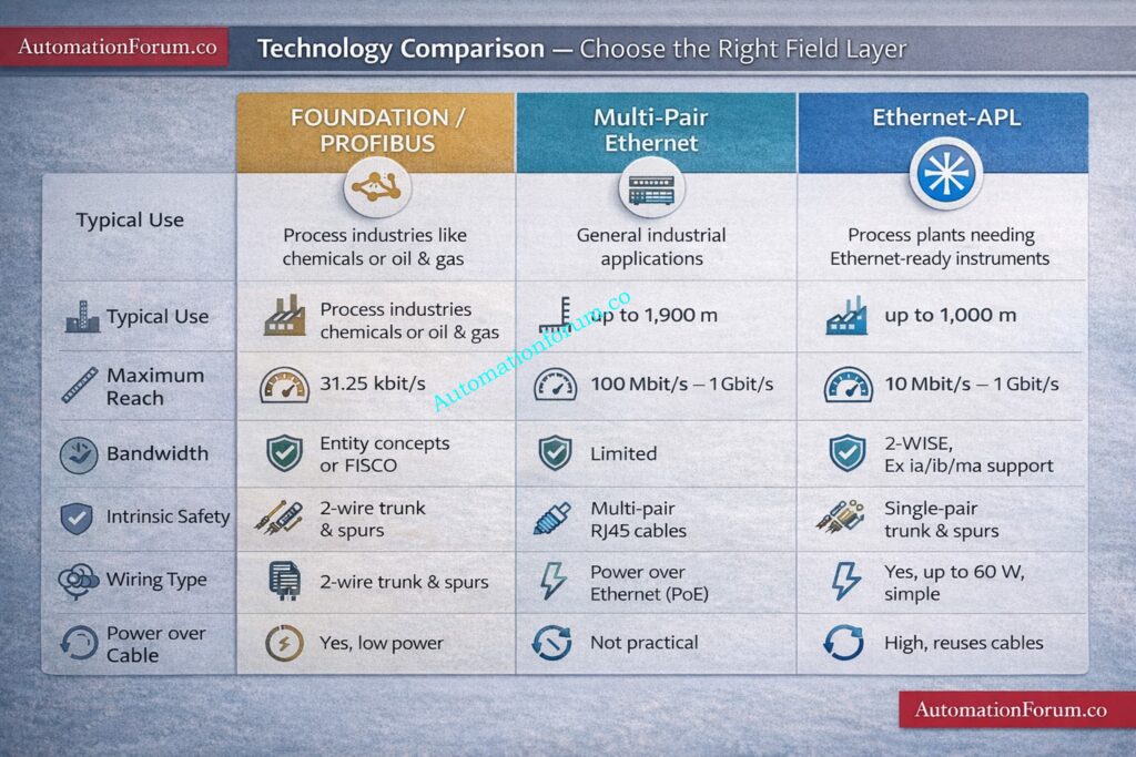
| Parameter | FOUNDATION / PROFIBUS | Multi Pair Ethernet | Single Pair Ethernet Ethernet APL 10BASE T1L |
| Typical use | Legacy analog and fieldbus sensors, transmitters, valve positioners | Plant backbone, control room switches, servers, DCS interconnections | Field devices in hazardous areas, smart transmitters, edge instrumentation |
| Maximum reach | Trunk and spur several kilometers depending on segment design | 100 m per copper segment | Trunks up to around 1000 m, spurs around 200 m |
| Bandwidth | Low, typically in kbps range | High, 100 Mbps to 1 Gbps common | 10 Mbps |
| Intrinsic safety | Proven and widely implemented | Limited support in field environments | Supported via two wire intrinsic safety concept 2 WISE |
| Wiring type | Two wire trunk and spur | Four pair copper cable | Two wire trunk and spur |
| Power over cable | Supported in bus powered segments | Supported via PoE but not suitable for Zone 0 1 field devices | Supported via defined APL port power classes |
| Retrofit potential | High in existing fieldbus plants | Moderate, often requires new cabling | High potential, reuse of Type A fieldbus cable possible |
| Typical environment | Field instrument level in process plants | Control room and plant network backbone | Field level including hazardous Zone 1 and Zone 2 areas |
| Engineering complexity | Well understood, mature tooling | Standard IT network practices | Requires port class, power budget and IS mapping discipline |
| Future scalability | Limited by bandwidth | Very high but short reach | Balanced reach and bandwidth for field digitalization |
Practical Interpretation for EPC Engineers
- FOUNDATION and PROFIBUS remain reliable for legacy brownfield environments but are bandwidth limited.
- Multi pair Ethernet is ideal for control room and backbone infrastructure but not suitable for long hazardous field runs.
- Ethernet APL bridges the gap by bringing native Ethernet to the field with long reach and intrinsic safety support.
Choosing Between Modbus TCP and PROFINET: Modbus TCP/IP vs Profinet: Which Protocol Suits your Industrial Network Best?
Engineering Checklist and Project Handover Procedure
Use the checklist below as the formal engineering handover and verification document.
| Task | Notes |
| Define APL segment classes in instrument spec | Specify port class, power class, and allowed cable categories |
| Create cable selection and routing plan | Include conductor sizes, jacket types, trays, and separation rules |
| Compute power budget per field switch | List steady and peak draw, include margin for growth |
| Prepare intrinsic safety mapping | Collect entity parameters and prove compliance per port |
| Procure certified field switches and devices | Require port profile statement and zone certificates |
| Design surge protection and earthing | Ensure SPD compatibility with IS mapping |
| Develop FAT test plan | Include LLDP link, power, and fault recovery cases |
| Publish site installation plan | Define termination procedures, torque values, and labeling |
| Run pre commissioning tests | Continuity, resistance, and insulation where applicable |
| Execute commissioning and FAT | Capture LLDP tables, packet traces, and power logs |
| Prepare maintenance and spare policy | List spare parts and support SLAs |
| Handover documentation | Deliver as built diagrams, FAT logs, certificates, and configuration files |
Complete HART & WirelessHART Installation Workflow: Step-by-Step Guide for Installing and Commissioning HART and WirelessHART Devices for Engineers and Technicians
Field Installation Checklist – Technician Quick Reference
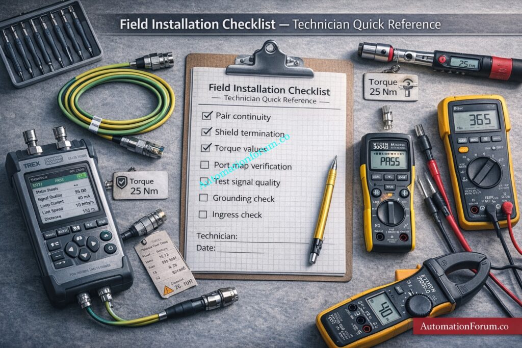
Use this checklist at the point of termination and commissioning.
| Done | Item |
| ☐ | Cables labeled and matched to drawings |
| ☐ | Pair continuity and resistance verified |
| ☐ | Shield continuity and earth lug installed |
| ☐ | Terminations torqued to vendor spec |
| ☐ | Spur length checked against allowed limit |
| ☐ | Connector seals and ingress checks completed |
| ☐ | Field switch earthing and surge protection installed |
| ☐ | Port mapping recorded and LLDP names captured |
| ☐ | Power budget verified per field switch |
| ☐ | Commissioning capture started and logs saved |
| ☐ | FAT test cases executed and signed |
| ☐ | As built updates filed to project document system |
How to Select the Right Modbus Baud Rate: Key Factors to Consider When Setting Baud Rate in Modbus Networks
Three EPC Case Studies
Case Study 1 – Brownfield Retrofit Replacing FOUNDATION Fieldbus
Problem: congested mechanical conduits and limited pull space.
Approach: reuse Type-A FF cable where permitted, install intrinsically safe APL power-limiting switches in marshalling, and deploy protocol gateways for coexistence during phased migration.
Outcome: minimized hook-up changes, maintained IS boundaries, and staged device replacement to control spend.
Most Important Industrial Communication Protocols Explained: Connecting the Industrial World: An Exploration of Communication Protocols in Automation and Instrumentation
Case Study 2 – Greenfield Chemical Plant Using Ethernet-APL
Problem: mixed device classes and long distances.
Approach: define primary trunks in safe corridors with APL switches in marshalling cabinets; calculate worst-case power budgets for simultaneous startup; select suppliers with IEC TS 63444 port profiles and 2-WISE certificates.
Result: easier wiring, better diagnostics, and centralized power control.
How Foundation Fieldbus H1 Works in Process Plants: Foundation Fieldbus H1 Technology
Case Study 3 – Offshore Installation with Corrosion and Lightning Exposure
Problem: corrosion and lightning exposure.
Approach: specify corrosion-resistant, sealed connectors, route trunks within bonded trays, deploy certified surge protection in safe areas, and choose armoured cable jackets rated for marine exposure.
Outcome: reduced corrosion failures and improved lightning resilience.
Quick Guide to Troubleshoot Modbus Communication Issues: Step by Step Procedure for Modbus Troubleshooting
Frequently Asked Questions (FAQ) – Ethernet-APL for EPC Engineers
What is the difference between PROFINET and Ethernet APL?
PROFINET is an industrial communication protocol used for controller and device communication in automation systems. Ethernet APL is a physical layer technology that enables Ethernet communication directly to field instruments over a two wire cable. PROFINET and other Ethernet protocols can run over Ethernet APL.
What is APL in network?
APL stands for Advanced Physical Layer. It is a networking technology designed for process industries that allows Ethernet communication and power transmission over a single two wire cable while supporting long distances and hazardous area installations.
How fast is Ethernet APL?
Ethernet APL has a data throughput of 10 Mbps. This speed is best for automating industrial processes since it has enough capacity for device communication, diagnostics, and asset management while still being able to reach long cables.
What is the difference between Ethernet APL and SPE?
Single Pair Ethernet (SPE) is a general Ethernet technology that transmits data over a single pair of wires. Ethernet APL is a specialized implementation of SPE designed for process plants, including long cable reach, power delivery, and intrinsic safety support.
What is the full form of Ethernet APL?
Ethernet APL stands for Ethernet Advanced Physical Layer. It is a physical layer technology that enables Ethernet connectivity to field instruments using a two wire cable infrastructure.
Is Ethernet APL intrinsically safe?
Yes. Ethernet APL uses a two-wire intrinsic safety paradigm to ensure inherently safe operation. This lets Ethernet communication happen in dangerous regions like Zone 1 and Zone 2 in process plants.
What is an APL device?
An APL device is any field instrument designed to communicate using Ethernet APL. Ethernet APL is an APL device. Pressure transmitters, temperature transmitters, flow meters, and field switches that can talk to each other over a two-wire cable are all examples.
Refer the below link to Test your Knowledge on Foundation Fieldbus Communication Protocol: Advanced Quiz for Instrumentation Engineers
 guide for EPC instrumentation & process automation: design checks, intrinsic safety (2-WISE), wiring, power budgets, commissioning.)