- Introduction
- ‘No-Response’ Errors
- What is a Modbus poll?
- CRC Errors
- Troubleshooting CRC Errors
- What is a Modbus exception?
- Exception Errors
- Modbus Debugging Tools-Modbus Poll
- Advanced Troubleshooting of Modbus
- Modbus RTU Troubleshooting – Verification Steps
- Modbus Polling Tools
- Key Considerations for Choosing the Best Modbus Polling Tool
- Modbus Troubleshooting Checklist
Modbus, a widely used communication protocol in industrial automation, allows for seamless transfer of information between devices. Like any technology, Modbus configurations can, however, run into problems that limit communication. In this comprehensive guide, we will go over a detailed Modbus troubleshooting approach, addressing frequent issues as well as providing remedies to ensure smooth and reliable operations.
Introduction

Modbus Troubleshooting is an essential capability for industrial automation professionals. The ability to quickly identify and rectify issues with communication enhances the effectiveness and reliability of Modbus configurations. This article explains a step-by-step approach for resolving typical Modbus issues and optimizing system performance.
‘No-Response’ Errors

Step 1 – Verify Communication Parameters
- Ensure that the communication parameters, including baud rate and parity, are accurately configured in Modbus Poll to match those of the Modbus devices.
Step 2 – Confirm Consistent Slave Address
- Confirm that the slave address set in Modbus Poll aligns with the assigned ID of the Modbus device under investigation.
- Mismatches can cause problems in communicating.

Step 3 – Inspect Modbus Wiring
- Examine the wiring connections within Modbus Poll to ensure they match the physical wire configuration of the RS485 network. Discrepancies can result in ‘no-response’ problems.

What is a Modbus poll?
Modbus Poll facilitates troubleshooting of Modbus server devices by providing features such as OLE Automation, customizable test scenarios, monitoring of serial data traffic, and data logging for in-depth analysis.
CRC Errors
What is CRC error in Modbus?
- A CRC (Cyclic Redundancy Check) error is an error-detection technique in data communication and storage systems.
- Utilizes a mathematical algorithm to generate a checksum from transmitted or stored data.
- Appends the checksum to the data for transmission.
- The receiver calculates its own checksum using the same algorithm.
- If the received checksum does not match the calculated checksum, a CRC error is flagged.
- Indicates potential data corruption or changes during transmission.
- Commonly used in communication protocols like Modbus to ensure data integrity.
- When a CRC error is detected, it often triggers a request for retransmission to maintain data accuracy.
- CRC is an error-detection method; it does not correct errors but identifies their presence.
In Modbus protocol, if there’s a CRC error during communication, it’s flagged by a specific exception code:
Exception Code 08: Memory Parity Error
This code (08) signals a CRC error or memory parity issue. It indicates that the data received by the Modbus device had a problem with CRC or parity, pointing to potential integrity issues in the transmitted data.
When troubleshooting Modbus communication, the appearance of exception code 08 suggests a CRC error.
Troubleshooting CRC Errors
Following the troubleshooting steps can help identify and address the root causes of these errors. Exception codes are crucial for communicating specific error conditions from the slave device to the master device in Modbus protocol.
Step 1: Check Communication Settings
- Verify the communication settings on both the transmitting and receiving ends.
- Ensure that parameters such as baud rate, parity, data bits, and stop bits match between the devices.
Step 2: Inspect Wiring
- Physically inspect the wiring between the communicating devices.
- Confirm proper wiring connections and grounding.
- Rectify any wiring issues that may contribute to CRC errors.
Step 3: Address Configuration
- Verify the device address and other addressing parameters.
- Ensure that the configuration in both devices matches.
- Correct any discrepancies in addressing to prevent CRC errors.
Step 4: Analyze Communication Logs
- Examine communication logs or error messages generated during Modbus communication.
- Look for patterns or specific error codes that can provide insights into the nature of CRC errors.
- Analyze error messages to identify potential solutions.
Step 5: Test Hardware Components
- Test the hardware components involved in communication (e.g., serial ports, communication modules).
- Verify the proper functioning of each hardware component.
- Replace or repair any faulty hardware.
Step 6: Consult Documentation
- Refer to the documentation for the Modbus protocol and devices involved.
- Seek guidance on troubleshooting CRC errors and resolving communication issues. Follow recommended procedures outlined in the documentation.
What is a Modbus exception?
Exception Errors
Exception Responses in Modbus:
Following a request, there are four possible outcomes from the slave:
- The request is successfully processed by the slave, and a valid response is sent.
- The slave does not receive the request, resulting in no response being sent.
- Alternatively, if the slave receives the request with a parity, CRC, or LRC error, it ignores the request and does not send a response.
- In cases where the slave receives the request without any error but cannot process it for another reason, no response is generated.
Function Code in Request and Exception Response:
- Function codes in a Modbus request are used to specify the type of operation to be performed by the slave.
- In an exception response, the function code is modified to indicate an exceptional condition. The highest bit of the function code is set to 1.
| Function Code in Request | Function Code in Exception Response |
| 01 (01 hex) 0000 0001 | 129 (81 hex) 1000 0001 |
| 02 (02 hex) 0000 0010 | 130 (82 hex) 1000 0010 |
| 03 (03 hex) 0000 0011 | 131 (83 hex) 1000 0011 |
| 04 (04 hex) 0000 0100 | 132 (84 hex) 1000 0100 |
| 05 (05 hex) 0000 0101 | 133 (85 hex) 1000 0101 |
| 06 (06 hex) 0000 0110 | 134 (86 hex) 1000 0110 |
| 15 (0F hex) 0000 1111 | 143 (8F hex) 1000 1111 |
| 16 (10 hex) 0001 0000 | 144 (90 hex) 1001 0000 |
Example Request and Exception Response:
Request:
0A 01 04A1 0001 AC63
- Slave Address: 0A (hex)
- Function Code: 01 (read Coil Status)
- Data Address: 04A1 (hex) (coil #1186)
- Number of Coils: 0001
- CRC: AC63
Exception Response:
0A 81 02 B053
- Slave Address: 0A (hex)
- Function Code: 81 (read Coil Status – highest bit set)
- Exception Code: 02
- CRC: B053
In this above example, the exception code ’02’ indicates that coil #1186 is an illegal address in the slave. This suggests that the coil has not been defined in the slave’s Modbus map.
Modbus Exception Codes:
These exception codes provide detailed information about various problems that could arise during Modbus communication, facilitating efficient diagnosis and corrective action.
| Exception Code | Name | Meaning |
| 01 (01 hex) | Illegal Function | The function code that was obtained from the request cannot be used by the slave. The function code may not be implemented in the chosen unit or may only apply to more newer devices. |
| 02 (02 hex) | Illegal Data Address | The data address provided in the query is not a valid address for the slave. |
| 03 (03 hex) | Illegal Data Value | A value within the query’s data field is not an acceptable value for the slave. |
| 04 (04 hex) | Slave Device Failure | The slave encountered an unrecoverable error while attempting to execute the requested action. |
| 05 (05 hex) | Acknowledge | The slave has acknowledged the request and is in the process of handling it, but an extended period of time is necessary for completion.This response prevents a timeout error in the master, and the master can issue a Poll Program Complete message to determine if processing is completed. |
| 06 (06 hex) | Slave Device Busy | The slave is currently occupied processing a program command that requires an extended duration. The master is advised to resend the message at a later time when the slave becomes available. |
| 07 (07 hex) | Negative Acknowledge | The slave is unable to execute the program function specified in the received query. This code is generated for an unsuccessful programming request involving function codes 13 or 14 in decimal. The master is recommended to request diagnostic or error information from the slave. |
| 08 (08 hex) | Memory Parity Error | Used in conjunction with specific function codes and reference types to indicate a parity error in memory. The slave attempted to read extended memory or record file but detected a parity error in memory. |
| 10 (0A hex) | Gateway Path Unavailable | Used with gateways to indicate that the gateway was unable to allocate an internal communication path for processing the request. Typically indicates that the gateway is either misconfigured or experiencing an overload. |
| 11(0B hex) | Gateway Target Device Failed to Respond | Used with gateways to indicate that no response was obtained from the target device. Typically signifies that the device is absent from the network. |
Review Controller’s Request
- Examine the controller’s request to verify its compatibility with the capabilities of the Modbus device. Exception errors commonly signal a request that the device is unable to understand or process.
Modbus Debugging Tools-Modbus Poll
Step 1 – Verify Communication Settings
- Ensure that the communication settings, including baud rate and parity, are accurately configured in Modbus Poll to match those of the Modbus devices.
Step 2 – Confirm Consistent Slave Address
- Confirm that the slave address set in Modbus Poll aligns with the assigned ID of the Modbus device under investigation. Mismatches can cause problems in communicating.
Step 3 – Inspect Modbus Wiring
- Examine the wiring connections within Modbus Poll to ensure they match the physical wire configuration of the RS485 network. Discrepancies can result in ‘no-response’ problems.
Advanced Troubleshooting of Modbus
If basic checks do not produce a resolution, then you should investigate the RS485 network further:
Step 1 – Use Shielded and Twisted RS485 Cables
- Use twisted and insulated cables for optimal RS485 transmission. Long-distance signal integrity is ensured by these cables, which block electromagnetic interference.
- In areas with electronic devices, the shielding serves as a barrier against outside influences. In industrial applications, induced noise can be eliminated by twisting the pair of cables, which increases reliability.
- Compatibility and ease of troubleshooting are ensured by these cables’ adherence to industry standards. Purchasing high-quality cables builds a strong basis for an RS485 network that is reliable and effective, which is essential for accurate and consistent data transfer.
Step 2 – Ensure Noise-Free Communication
- In order to maintain the optimal possible RS485 performance, unshielded cables must be eliminated as a potential source of interruption.
- The reliability of communication can be affected by noise introduced by random cables lacking insulation.
- To reduce electromagnetic interference, replace out these wires for shielded ones. In RS485 networks, this step ensures a noise-free environment, preventing signal degradation and ensuring smooth transmission of data.
- Investing in appropriate shielding is a low-cost way to improve the overall stability and efficiency of your communication system.
Step 3 – Advocate for Daisy-Chain Bus Configuration

- To effectively prevent data corruption, choose an RS485 bus configuration in daisy-chain topology.
- Reliable communication is ensured by this sequential structure, which reduces reflections. ‘Star’ or ‘Stub’ layouts should be avoided due to possible signal integrity problems.
- Because it improves performance, the daisy-chain design is the best option for a stable and efficient RS485 network.
Step 4 – Avoid Routing with Power Cables
- Segregate Modbus communication cables from power cables to prevent interference. Routing them together risks introducing noise, degrading performance.
- Maintaining a clear separation ensures optimal signal integrity and reliable RS485 communication.
Step 5 – Emphasize Termination Resistor Necessity

- Make sure that RS485 communication is reliable by underlining the need for termination resistors.
- These resistors stop signal reflections on the line from corrupting data. In order to prevent communication problems, ensure a clean, consistent signal, and eliminate signal bounce-back, proper termination is essential.
- To maximize efficiency and preserve data transmission integrity, install termination resistors at both ends of the RS485 bus.
Step 6 – Adhere to Single Master Principle
- Adhere to the single-master principle in Modbus-RTU protocol, supporting only one master device. Discourage multiple masters to prevent interference, ensuring smooth network operation.
- Modbus-RTU’s design favors a single master, enhancing system stability and preventing conflicts that may arise from simultaneous master operations.
Modbus RTU Troubleshooting – Verification Steps
Step 1 – Ensure Factory Default Settings
- Ensure that Modbus parameters match the factory default settings to prevent configuration-related issues.
Step 2 – Verify Baud Rate and Format
- Confirm the baud rate and character format settings to prevent CRC errors.
Step 3 – Verify Correct Polarity
- Verify correct polarity on RS485 lines and provide guidance on wire swapping if needed.
Step 4 – Guide on Setting Slave Addresses
When setting up Modbus RTU slave addresses:
- Assign a unique address to each device.
- Ensure addresses match device settings.
- Confirm no address conflicts between devices.
- Follow the Modbus standard for address range (1-247).
- Proper addressing facilitates seamless communication in the network.
Step 5 – Comprehensive Network Check
- Confirm biasing resistors (around 120 ohms) at each end, correctly connected.
- Verify termination resistors (120 ohms) at both ends, avoiding parallel terminations.
- Inspect cables for proper shielding, twisting, and separation from power lines.
- Adhere to the single-master principle for Modbus-RTU.
- Select an optimal communication speed, testing reliability and adjusting if necessary. Regularly monitor and fine-tune for peak performance.
Step 6 – Ensure Correct Device Configuration
- Ensure that slave devices are correctly configured for Modbus communication.
Step 7 – Offer Guidance on Speed Selection
- Selecting the appropriate communication speed is crucial for efficient Modbus communication. Consider factors like the network size, distance, and device capabilities.
- Start with a moderate baud rate and test system reliability. Gradually increase the speed if conditions permit, but be cautious not to exceed the device’s or cable’s capacity, ensuring a balance between speed and data integrity. Regularly monitor performance to fine-tune the communication speed for optimal efficiency.
Step 8 – Emphasize Cable Routing Best Practices
- For the best RS485 transmission, use twisted, insulated cables. These cables provide long-distance signal integrity protection by preventing electromagnetic interference.
Modbus Polling Tools
Commercial Tools:
- Supports Modbus RTU, ASCII, and TCP/IP.
- Real-time charting, data logging, and advanced analysis.
- Offers Modbus communication tools, including polling and monitoring.
- Integrates with SCADA and HMI systems.
- Industrial automation platform with built-in Modbus polling capabilities.
- Powerful energy management solution with Modbus polling.
- Comprehensive automation platform with Modbus communication libraries.
Open-source and Free Tools:
Python library for flexible Modbus communication.
Flow-based visual programming tool with Modbus nodes.
Open-source software for Modbus TCP/IP communication.
Comprehensive C# library for Modbus communication.
Qt-based open-source library for Modbus communication.
Additional Options:
- PLC and HMI Software:Many PLCs and HMIs have built-in Modbus polling capabilities.
- Web-based Tools:Some web-based tools offer Modbus polling and monitoring.
- Hardware Options:Modbus gateways and data loggers for polling multiple devices.
Key Considerations for Choosing the Best Modbus Polling Tool
- Verify compatibility with the specific Modbus variant used by your devices.
- Ensure support for both Modbus RTU and Modbus TCP/IP protocols.
- Evaluate the tool’s data logging capabilities for recording and analyzing historical data.
- Check for options to export or visualize logged data.
- Assess whether the tool provides advanced analysis features, such as real-time charting or statistical analysis.
- Consider tools that support scripting or automation for customization to specific use cases.
- Ensure seamless integration with SCADA, HMI, or other automation systems.
- Check for compatibility and ease of integration to avoid workflow disruptions.
- Evaluate the level of technical expertise required to use the tool effectively.
- Consider user-friendliness for persons with little programming or automation skills.
- Consider budget limits, such as license fees for commercial products or higher charges for open-source options.
- Consider the overall cost of ownership, taking into account any necessary software or hardware.
Click to know more about Modbus
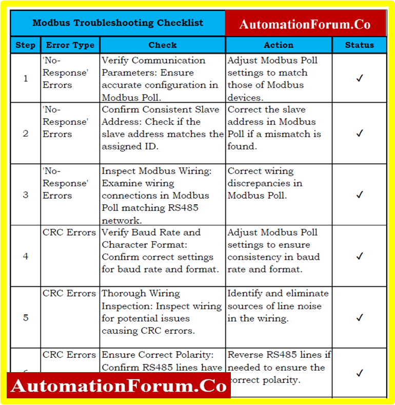
Modbus Troubleshooting Checklist
Click on the link below for a downloadable Troubleshooting Checklist for Modbus in excel form