- What is Modbus?
- What is Modbus used for?
- How does Modbus work?
- Master and Slave in Modbus
- How Data is Stored in Standard Modbus
- What is the Slave ID in Modbus?
- What is a function code in Modbus?
- What CRC is used in Modbus?
- What is the function of CRC in Modbus?
- What is the LRC in Modbus?
- Types of Modbus
- Modbus RTU vs Modbus TCP – Comparison Table
- What is a Modbus frame?
- Modbus Command and Response Formats
- Modbus TCP Message Structure
- How to Read a Modbus Request
- Mobus Simulators and Troubleshooting Tools
What is Modbus?
- Modbus, introduced by Modicon(www.modicon.com) in 1979, stands as a serial communication protocol specifically designed for deployment with its programmable logic controllers (PLCs).
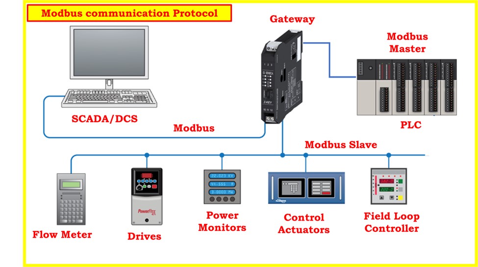
- Basically, it functions as a mechanism for the transfer of data between electronic devices when it is transmitted over serial lines.
- Within this framework, the entity seeking data is denoted as the Modbus master, while those providing data are referred to as Modbus slaves.
- In a typical Modbus network, a singular master exists alongside up to 247 Slaves, each assigned a unique slaves Address ranging from 1 to 247. Additionally, the master possesses the capability to transmit information to the slaves.
What is Modbus used for?
- Modbus, as an open protocol, is freely available for integration into equipment by manufacturers, eliminating the need for royalty payments.
- It has emerged as a standard communication protocol in various industries and stands as the most prevalent method for linking industrial electronic devices.
- Its widespread adoption spans across numerous manufacturers and diverse sectors. In practical applications, Modbus is commonly employed for transmitting signals from instrumentation and control devices to a central controller or data collection system.
- For instance, it facilitates the communication of temperature and humidity measurements from a system to a computer. In supervisory control and data acquisition (SCADA) systems, Modbus is frequently utilized to establish a connection between a supervisory computer and a remote terminal unit (RTU).
- Notably, different versions of the Modbus protocol cater to serial lines (Modbus RTU and Modbus ASCII) as well as Ethernet (Modbus TCP).
How does Modbus work?
- Modbus, a widely used serial communication protocol, operates by facilitating data exchange between electronic devices.
- In its basic configuration, a straightforward connection involves a single serial cable linking the serial ports of two devices: a master and a slave.
- At the core of Modbus communication is the transmission of data through binary code, represented as a series of ones and zeroes, also known as bits.
- These bits are conveyed through voltage variations. Zeroes are transmitted as positive voltages, while ones are represented by negative voltages.
- The rapid transmission of these bits characterizes the efficiency of Modbus communication. A common transmission speed for Modbus is 9600 baud, denoting the number of bits transmitted per second.
Master and Slave in Modbus

Role of Modbus Master
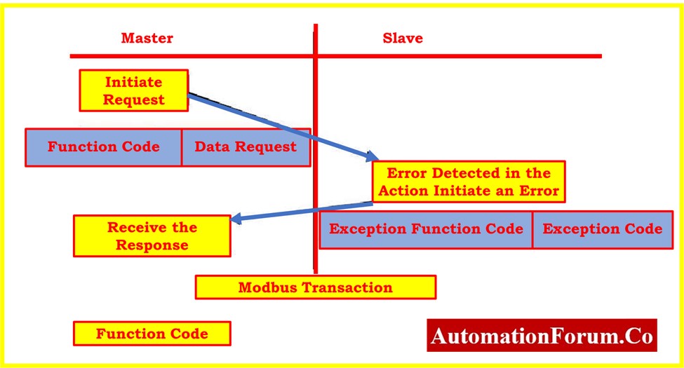
- Modbus follows a master-slave architecture, where the master initiates requests, and the slave responds. The Master, often a supervisory system or controller, sends a request to the slave, typically a field device or sensor, to obtain or manipulate data.
- This request includes essential information such as the salve’s address, function code specifying the type of operation, and data parameters.
Role of Modbus Slave
- Upon receiving the request, the slave processes the command and transmits the requested data back to the master.
- This bidirectional communication allows for real-time monitoring and control of industrial processes.
- The use of unique slave addresses (ranging from 1 to 247) ensures that each device on the network can be individually identified and addressed by the master.
How Data is Stored in Standard Modbus
- In Standard Modbus, data is organized and stored within the slave device across four distinct tables.
- These tables are categorized into two types: on/off discrete values (coils) and numerical values (registers).
- Each type further includes a read-only table and a read-write table, resulting in a total of four tables.
- Notably, each table can accommodate up to 9999 values.
- For the coils and registers, each possesses a data address within the range of 0000 to 270E. Coils, representing 1-bit on/off discrete values, and registers, serving as containers for numerical data, share this addressing scheme.
- Registers, being 16 bits or 2 bytes each, also have data addresses ranging from 0000 to 270E.
- The Coil/Register Numbers can be compared to location names in that they serve as identifiers inside the tables but do not appear in the actual messages transferred between devices.
- The crucial element used in the messages is the Data Address. To illustrate, consider the first Holding Register with the number 40001; its corresponding Data Address is 0000.
- The distinction between these two values is referred to as the offset. Each table is associated with a specific offset, which varies for the four tables: 1, 10001, 30001, and 40001.
Summary Table of Coils and Registers
Here’s a table summarizing the key information for coils and registers in Standard Modbus, including their numbers, data addresses, data types, and table names:
| Type | Coil/Register Number | Data Address | Data Type | Table Name |
| Discrete Input | 00001 – 09999 | 0000 – 270E | Bit | Input Status |
| Coils | 00001 – 09999 | 0000 – 270E | Bit | Output Status |
| Input Register | 30001 – 39999 | 0000 – 270E | 16-bit | Input Register |
| Holding Register | 40001 – 49999 | 0000 – 270E | 16-bit | Holding Register |
What is the Slave ID in Modbus?
- In Modbus communication, each slave device on the network is assigned a unique unit address ranging from 1 to 247.
- This address(ID) is crucial for the proper identification of the intended recipient of the message. The slave address is the first byte of the message sent by the master, allowing each slave device to quickly determine whether the message is meant for it.
- This addressing mechanism ensures efficient and targeted communication within the Modbus network, as each slave device can decide whether to process or ignore the incoming message based on its assigned address.
What is a function code in Modbus?
- In the Modbus protocol, the function code is a numerical code that indicates the type of action the master requests the slave to perform.
- The function code is the second byte sent by the master in a Modbus message. It specifies the operation or function that the slave should execute, including which table to access and whether the operation involves reading from or writing to the table.
Common Function Codes (01, 02, 03, 04, 05, 06, 15, 16)
Here’s a table with some common Modbus function codes:
| Function Code | Action | Table Name |
| 01 | Read Coils | Discrete Output Coils |
| 02 | Read Discrete Inputs | Discrete Input Contacts |
| 03 | Read Holding Registers | Analog Output Holding Registers |
| 04 | Read Input Registers | Analog Input Registers |
| 05 | Write Single Coil | Single Discrete Output Coil |
| 06 | Write Single Register | Single Analog Output Holding Register |
| 07 | Read Exception Status | – (Depends on the device) |
| 08 | Diagnostic | – (Depends on the device) |
| 15 | Write Multiple Coils | Multiple Discrete Output Coils |
| 16 | Write Multiple Registers | Multiple Analog Output Holding Registers |
How Function Codes Determine Read/Write Operations
- These function codes are just a selection of the many codes defined in the Modbus standard. Each code has a specific purpose, instructing the slave on how to process the request.
- For instance, Function Code 03 instructs the slave to read holding registers, while Function Code 06 instructs the slave to write a single register.
- The combination of the slave address (unit ID), function code, and additional data forms a complete Modbus message, enabling communication between the master and slave devices in a Modbus network.
What CRC is used in Modbus?
- CRC stands for Cyclic Redundancy Check, is a method used in Modbus and many other communication protocols to detect errors in transmitted data.
- In Modbus, a CRC is a two-byte (16-bit) field added to the end of every message for error detection purposes.
What is the function of CRC in Modbus?
Here is some other information about how Modbus CRC functions:
Calculation during Transmission:
- The CRC is calculated based on every byte in the Modbus message, including the address, function code, data, and any other relevant fields.
- This calculation uses a mathematical algorithm to generate a unique CRC value for the specific content of the message.
Appended to Message:
- The calculated CRC value is then appended to the end of the message.
Verification at the Receiver:
- When the slave(receiver) receives the message, it also performs the CRC calculation on the received data, excluding the appended CRC field.
- The calculated CRC at the slave (receiver) should match the CRC appended to the message by the master(sender).
Error Detection:
- If the CRC calculated by the receiver does not match the CRC received in the message, it indicates a potential error in the transmission.
- If the CRCs do not match, the receiving device can request the sender to resend the message.
Modbus uses CRC to detect errors, which helps to ensure the integrity of the data during transmission. The CRCs will probably differ if the message changes by even a single bit while it is being transmitted, indicating that there is a problem. This system improves Modbus communication reliability.
What is the LRC in Modbus?
In the context of Modbus, Longitudinal Redundancy Check (LRC) is an error-checking method used in the Modbus RTU (Remote Terminal Unit) communication protocol. LRC is specific to Modbus RTU, which is designed for serial communication over RS-232 or RS-485.
LRC Calculation Process
Modbus RTU’s LRC operates in the following way:
- LRC is calculated by performing an XOR (exclusive OR) operation on all bytes of the message, including the device address, function code, data, and any other relevant fields.
- The result of the XOR operation is then complemented (bitwise NOT) to obtain the final LRC value.
- The LRC value is typically appended to the end of the message frame, just before the stop bits.
- LRC is a single-byte check, providing a simple form of error detection.
- Upon receiving a message, the receiving device performs the same XOR and complement operations on the received bytes. If the calculated LRC matches the received LRC, the message is considered to be error-free.
- LRC is effective at detecting certain types of errors, such as single-bit errors.It might not be as reliable, though, as advanced error-checking techniques like Cyclic Redundancy Check (CRC).
Types of Modbus
- Modbus is a communication protocol commonly used in industrial automation and control systems.
- There are different variants or types of Modbus protocols, each serving specific purposes. The two main types are Modbus RTU and Modbus TCP.
Modbus RTU (Remote Terminal Unit):
In industrial contexts, Modbus RTU is a commonly used protocol, especially when using serial communication is helpful. It is appropriate for a variety of industrial automation and control applications because of its stability and ease of implementation.
Frame Structure:
- Modbus RTU uses a master-slave communication model.
- The communication frame consists of a start bit, device address, function code, data, CRC (Cyclic Redundancy Check), and stop bits.
- The frame structure allows for multiple devices to be connected on the same network.
Error Detection:
- Modbus RTU incorporates error-checking through CRC, which helps in detecting communication errors.
Addressing:
- Devices on a Modbus RTU network are identified by unique addresses.
- Address range for Modbus RTU devices is typically from 1 to 247.
Master-Slave Architecture:
- The master initiates communication by sending requests to the slaves.
- Slaves respond to the master’s requests, and each device has its own address to differentiate between them.
RS-485 vs. RS-232:
- While RS-232 is suitable for short-distance point-to-point communication, RS-485 is often preferred for longer distances and multi-drop configurations.
- RS-485 allows for the daisy-chaining of devices, which can be more cost-effective and practical in certain applications.
Speed Considerations:
- Modbus RTU typically operates at lower speeds compared to Modbus TCP, which uses Ethernet as its physical layer.
- Transmission speeds can vary but are generally in the range of 9600 to 115200 bits per second.
Industrial Applications:
- Modbus RTU is widely used in industrial automation and control systems.
- It is commonly employed in applications where wired serial communication is a preferred or necessary choice due to factors like reliability and environmental conditions.
Stability:
- The simplicity and efficiency of Modbus RTU make it a robust and reliable choice for many industrial communication needs.
Modbus TCP (Transmission Control Protocol):
Modbus TCP, which uses Ethernet for communication, is a logical development of the Modbus protocol. With benefits in speed, range, and compatibility with current network infrastructure, it is commonly used in modern industrial systems with Ethernet connectivity.
Communication Medium:
- Modbus TCP utilizes Ethernet as the communication medium.
- This enables it to take advantage of the widespread use and familiarity of Ethernet in industrial and commercial environments.
Data Representation:
- Unlike Modbus RTU’s binary encoding, Modbus TCP uses a format compatible with the TCP/IP suite.
- This means that it encapsulates Modbus frames into TCP packets, allowing for seamless integration with Ethernet networks.
Topology:
- Modbus TCP is well-suited for Ethernet networks, offering flexibility in terms of network topologies.
- It can be used in star, ring, bus, or other network configurations commonly found in Ethernet-based setups.
Transmission Speed:
- Modbus TCP generally operates at higher speeds compared to Modbus RTU.
- The use of Ethernet as the underlying transport layer contributes to faster data transmission.
IP Addressing:
- Devices on a Modbus TCP network are identified using IP addresses, making it easier to integrate into existing TCP/IP network infrastructures.
Master-Slave Architecture:
- Similar to Modbus RTU, Modbus TCP follows the master-slave architecture.
- The master initiates communication by sending requests to the slaves, and the slaves respond accordingly.
Interoperability:
- Modbus TCP’s compatibility with the TCP/IP suite enhances interoperability with other networking protocols and technologies commonly used in modern industrial systems.
Advantages:
- Modbus TCP offers advantages in terms of speed, longer-distance communication, and compatibility with existing Ethernet infrastructure.
- It is well-suited for applications where real-time communication, large amounts of data, and integration with other Ethernet-based systems are important.
Security Considerations:
- As with any communication protocol, security measures need to be implemented to protect Modbus TCP networks from unauthorized access or attacks.
- This may include the use of firewalls, virtual private networks (VPNs), and other security protocols.
Modbus RTU vs Modbus TCP – Comparison Table
The equipment and situations used in a given industrial system may cause specific implementations to differ from these general characteristics. The following table provides an overview of the key differences between Modbus RTU and Modbus TCP:
| Characteristic | Modbus RTU | Modbus TCP |
| Communication Method | Serial (RS-232 or RS-485) | Ethernet (TCP/IP) |
| Data Representation | Binary | Compatible with TCP/IP suite |
| Topology | Point-to-point or multi-drop | Flexible (typical Ethernet topologies) |
| Transmission Speed | Typically lower | Generally higher |
| Typical Use | PLC systems, serial communication | Modern industrial systems, Ethernet |
| Physical Layer | Serial | Ethernet |
| Distance | Shorter distances | Longer distances (typical Ethernet) |
| Interoperability | May require additional hardware | Integrated with existing Ethernet infrastructure |
| Ease of Troubleshooting | Simpler for serial diagnostics | Network diagnostics and monitoring tools |
What is a Modbus frame?
A Modbus frame refers to the structure of data transmitted over a Modbus network.
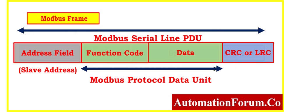
A Modbus frame consists of the following elements:
Address Field:
This field identifies the device (or slave) on the Modbus network that the message is intended for. Each device on the network has a unique address.
Function Code:
The function code specifies the type of action the device should perform. For example, it could indicate a read operation, write operation, or diagnostic function.
Data Field:
This field contains the actual data being sent or requested. The format and content of the data field depend on the specific function code and the purpose of the message.
Error Checking:
Modbus frames typically include a form of error-checking to ensure the integrity of the transmitted data. This can be a simple checksum or a more sophisticated cyclic redundancy check (CRC).
Modbus Command and Response Formats
Below is a simplified table illustrating the basic structure of Modbus commands and responses for the Modbus RTU (Remote Terminal Unit).
The examples provided are for a common Modbus function code, “Read Holding Registers” (Function Code 03), as an illustration.
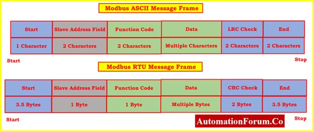
Modbus RTU Frame Format:
Command: Read Holding Registers (Function Code 03)
| Field | Size (Bytes) | Description |
| Start of Frame | 1 | Silent interval or frame start delimiter |
| Slave Address | 1 | Address of the target device (1 to 247) |
| Function Code | 1 | Specifies the type of action to be performed (03 for Read Holding Registers) |
| Data | Variable | Parameters specific to the function code |
| Error Check | 2 | CRC (Cyclic Redundancy Check) for error detection |
| End of Frame | 1 | End of frame delimiter |
Response: Read Holding Registers
| Field | Size (Bytes) | Description |
| Start of Frame | 1 | Silent interval or frame start delimiter |
| Slave Address | 1 | Address of the responding device |
| Function Code | 1 | Echo of the received function code |
| Byte Count | 1 | Number of bytes in the Data field |
| Data | Variable | Actual data read from holding registers |
| Error Check | 2 | CRC for error detection |
| End of Frame | 1 | End of frame delimiter |
Modbus ASCII Frame Format:
Command: Read Holding Registers (Function Code 03)
| Field | Size (Characters) | Description |
| Start of Frame | 1-2 | Colon character (:) repeated twice |
| Slave Address | 2 | Address of the target device (ASCII characters) |
| Function Code | 2 | ASCII representation of the function code (03) |
| Data | Variable | ASCII representation of parameters |
| LRC (Longitudinal Redundancy Check) | 2 | ASCII representation of LRC |
| End of Frame | 2 | Carriage return (CR) and line feed (LF) characters |
Response: Read Holding Registers
| Field | Size (Characters) | Description |
| Start of Frame | 1-2 | Colon character (:) repeated twice |
| Slave Address | 2 | Address of the responding device |
| Function Code | 2 | ASCII representation of the function code |
| Byte Count | 2 | ASCII representation of byte count |
| Data | Variable | ASCII representation of actual data read |
| LRC (Longitudinal Redundancy Check) | 2 | ASCII representation of LRC |
| End of Frame | 2 | Carriage return (CR) and line feed (LF) characters |
Remember that the unique Modbus function code and the parameters used in the command or response will decide the actual data content and lengths. Also, error-checking mechanisms like CRC and LRC are used to make sure that the data being sent is accurate.
Modbus TCP Message Structure
Modbus TCP utilizes a TCP/IP link for the transmission of Modbus messages. The format of a Modbus TCP message is as follows:

| Field | Size | Description |
| Transaction Id | 2 Bytes | Identifies the transaction. |
| Protocol | 2 Bytes | Set to zero to indicate the Modbus protocol. |
| Length | 2 Bytes | Specifies the number of following bytes. |
| Unit Address | 1 Byte | Represents the PLC Address encoded as a single byte. |
| Message | N Bytes | Contains the Modbus Protocol Data Unit (PDU) with a maximum length of 253 bytes. |
Notes on Unit Address Usage:
Real Modbus TCP devices exhibit variations in the utilization of the Unit Address field:
- Some devices may choose to ignore the Unit Address field.
- Certain devices might mandate a fixed value for the Unit Address, such as 0 or 255.
- Some devices function as gateways to multiple PLCs, where the Unit Address determines the specific PLC to communicate with.
Maximum Message Length:
The maximum allowable length for the entire Modbus TCP message is 260 bytes.
Understanding the diverse ways in which the unit address is employed is crucial for configuring communication with Modbus TCP devices, as this aspect may differ among various devices. Always refer to the documentation provided by the specific Modbus TCP device for accurate details on its unit address implementation.
How to Read a Modbus Request
To read a Modbus request, you need to capture and analyze the raw data transmitted over the Modbus network. Below is an example of how you might read a Modbus RTU request
In this example, consider a Modbus RTU “Read Holding Registers” request (Function Code 03).
Assuming you have captured a Modbus RTU request frame:

- Slave Address (01): The request is for the Modbus device with the address 01.
- Function Code (03): This code indicates the request is to read data from holding registers.
- Register Address (0000): The starting register address to read from is 0000.
- Number of Registers (0002): The request is asking to read data from two consecutive registers.
This request simply asks the Modbus device at address 01 to provide the values stored in the holding registers starting at address 0000, and it specifically requests data from the first two registers.
Mobus Simulators and Troubleshooting Tools
Free Modbus Simulators:
- Modbus Poll:
Popular and user-friendly simulator for both master and slave devices. Supports various Modbus versions (RTU, ASCII and TCP/IP). Provides real-time data monitoring and diagnostic tools.
Download link : Modbus Poll
- pyModbus:
Open-source Python library for simulating Modbus communication. Highly customizable and scriptable option for advanced testing conditions.
Download link : pyModbus
- Modbus Simulator Online:
Simple web-based simulator for quick testing and learning. Supports Modbus RTU and TCP/IP. No installation required, good for basic testing and learning..
Download link: Modbus Simulator Online
Paid Modbus Simulators:
- Citect Automation Studio:
Comprehensive industrial automation software with advanced Modbus simulation capabilities. Offers powerful testing and debugging tools for complex networks.
Free trial available, download link on Citect Automation Studio.
- Rockwell Automation RSLogix 500/5000:
Programmable logic controllers (PLCs) with built-in Modbus simulation features. Ideal for testing real-world PLC communication situations.
Requires purchase of hardware and software. Click Rockwell Automation for details.
Modbus Troubleshooting Software Tools:
- Wireshark:
Network protocol analyzer for capturing and analyzing Modbus communication packets. Helps to identify errors and diagnose network issues.
Download link : Wireshark
- Modbus Tools Suite:
Paid Modbus analysis and troubleshooting tools. Error tracking, protocol decoding, and data visualization. Click here for Modbus Tools Suite
- Fluke Networks EtherScope Network Assistant:
Multi-purpose network troubleshooting tool with Modbus analysis capabilities. Ideal for field engineers and network administrators.
Click here Fluke Networks for download options.