- Incident Summary: 36 Temperature Tags Dropped to Zero and Alarm Flooding
- Timeline & Initial Symptoms
- Field Response: Safety, Permit to Work and First Actions
- Multiplexer Observations and Spare Selection
- Replacement Procedure (step-by-step)
- Unexpected Escalation – Area Two Collapse
- Diagnosis: Duplicate Modbus Slave ID (root cause)
- Immediate Corrective Actions Taken
- Corrective & Preventive Controls to Implement
- SOP Checklist & Troubleshooting Quick-reference
- Practical Modbus Scanner and PLC Diagnostics Steps
- Preventive Controls and Process Changes to Implement
- Organizational Rules and Access Control
- Example Sop
- KPI And Monitoring Suggestions After Implementation
- Incident Report
- Final Actionable Takeaway for Plant Teams
- Frequently Asked Questions On Duplicate Modbus Address Issues
Incident Summary: 36 Temperature Tags Dropped to Zero and Alarm Flooding
This case study shows how using the same Modbus address in temperature multiplexers caused wrong readings and how the problem was found and fixed.
Timeline & Initial Symptoms
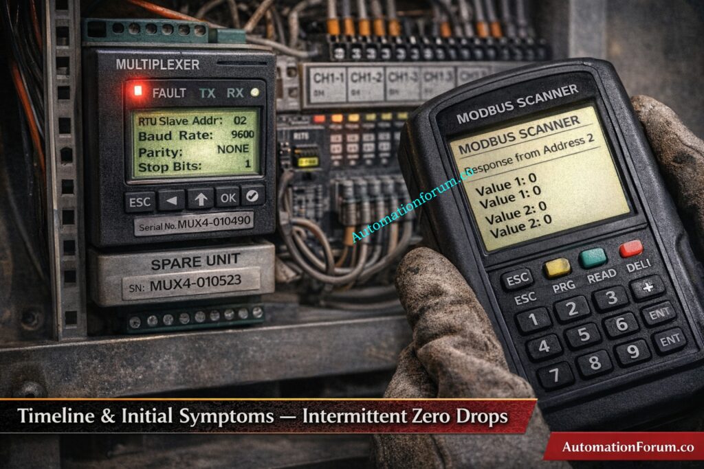
Two Days Of Intermittent Zero Drops And Final Collapse
- Control room operators experienced alarm overload that made it difficult to prioritize actions, and the combined loss of multiple temperature signals created immediate process safety concern and increased the probability of manual or automated trips. Restoring visibility was the top priority to keep plant systems within safe operating envelopes.
- Area One showed intermittent zero drops for two days prior to the incident, with values collapsing for a few seconds and then recovering automatically, which led field teams to initially suspect transient noise grounding or sensor instability. The intermittent nature deferred higher urgency until the final sustained collapse.
- The instrumentation engineer came to site under a permit to work to inspect the Area One multiplexer, confirm the fault condition, remove the suspected device, install a spare, and attempt rapid restoration of critical temperature visibility while coordinating tightly with operations.
Choosing the Wrong Protocol Can Shut Down Your Industrial Network: Modbus TCP/IP vs Profinet: Which Protocol Suits your Industrial Network Best?
Field Response: Safety, Permit to Work and First Actions

Permit, PPE and Control Room Historian Review
- The instrumentation engineer arrived on site, obtained the permit to work, completed the safety briefing, verified PPE levels and confirmed lockout tagout points before opening enclosures or touching equipment. The permit to work sheet kept track of all planned activities.
- The engineer looked at alarm lists and PLC historian trends in the control room to figure out which process variables went with which multiplexer channels and mark the timestamps. This cut down on the time spent in the field. This phase made sure that the field visit was focused on the right hardware.
- Communications with operations were continuous during the activity so that any power isolation or restart was coordinated, process impact was minimized and control room operators were prepared to follow emergency procedures if unexpected consequences occurred.
Wrong Modbus Baud Rate Causes Intermittent Communication Failures: Key Factors to Consider When Setting Baud Rate in Modbus Networks
Multiplexer Observations and Spare Selection
Fault Led, Bench History And Why Bench Resets Are Critical
- The multiplexer was powered on and showed a continuous red fault LED while measured supply voltage remained within acceptable limits, making a supply failure unlikely and pointing attention toward device internal fault or configuration anomalies.
- The enclosure showed no signs of wiring damage, corrosion, or loose cable terminations. This made it less likely that the device would fail mechanically and supported a replacement plan that used a spare device to speed up recovery.
- The engineer ran a controlled power cycle while the control room watched the PLC’s behaviour. The fault LED stayed on after the reboot, which confirmed that the device did not recover and that replacing it was the best way to swiftly restore measurements.
- For the incident report and any vendor support or warranty return, device details including the serial number, model, and fault LED behaviour were recorded. This kept the information traceable for further study.
Spare Selection And Preinstall Checks
- The engineer took a preconfigured spare multiplexer from the maintenance store and looked at the bench record, which revealed that the spare had been used on a test bench lately. This showed that the configuration needed to be checked before connecting to a live network.
- Physical checks of the spare included checking the connectors, harnesses, mounting tabs, and grounding continuity to make sure the item was ready to be installed in the field and wouldn’t cause any problems with wiring or grounding.
- The engineer worked with operations to set up a replacement window and made sure that the PLC would behave as expected during the removal. This way, control room staff could see trends before and after the removal and respond right away to any unexpected alarms.
- The spare front panel was inspected for address and communication parameter visibility though at this stage the spare was assumed ready for field use; the subsequent diagnosis showed why explicit verification of slave ID is mandatory prior to energizing on the live bus.
Fail This Modbus Quiz and Fail the Automation Interview: MODBUS Protocol Quiz :Test Your Knowledge
Replacement Procedure (step-by-step)
Isolation, Removal, Wiring Best-Practices and Grounding Checks
- The engineer isolated power at the approved isolation point, removed the faulty multiplexer while documenting the removed unit serial number and observed LED fault state, and prepared the enclosure for mounting the spare. The work order kept track of everything that happened.
- The spare multiplexer was put in the same place, and the wire was re-terminated according to the designs, paying close attention to shield terminations, terminal torque, and cable routing to keep the signal clear and cut down on electromagnetic interference.
- Before restoring power, the continuity of the ground between the enclosure and shield terminations was checked to make sure that the installation wouldn’t add noise to the measurement loops.
Modbus Communication Failure Can Stop Production Completely: Step by Step Procedure for Modbus Troubleshooting
Unexpected Escalation – Area Two Collapse
Timestamps And Correlation That Pointed To A Network Conflict
- The control room and field crew looked at the timestamps of the events and saw that the values in Area Two matched the time when the spare was turned on in Area One. This clearly suggests that there was a network-level conflict rather than two devices failing at the same time.
- The engineer worked with operations to set up a controlled isolation test. They turned off the Area Two multiplexer for a short time while keeping an eye on the PLC to see what data was still on the bus and how mapping changed when devices were taken away.
Poor Modbus Knowledge Leads to Costly Plant Downtime: Modbus Protocol – Complete Guide for Automation Engineers
Diagnosis: Duplicate Modbus Slave ID (root cause)
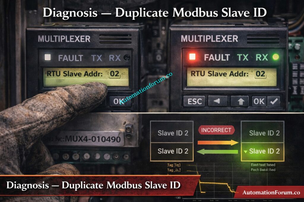
- The engineer looked at the spare multiplexer front panel and checked the communication settings. This confirmed that the slave ID had been modified during bench testing and had not been reset to a unique spare address before installation.
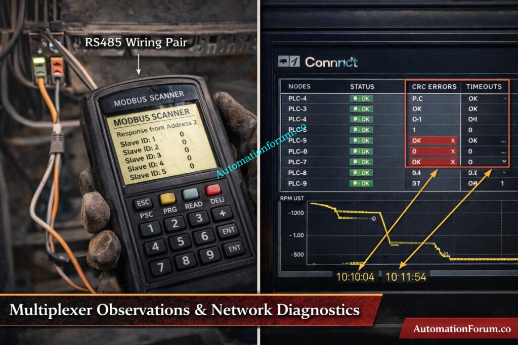
- We connected a handheld Modbus scanner to the RS485 bus and used it to check for expected slave IDs. The scanner data showed overlapping responses and frame durations that didn’t match up, which meant that more than one device was responding to the same address.
- We looked at the PLC communication diagnostics and saw that there were more CRC failures, timeouts, and retry counts during the conflict. These diagnostics backed up the scanner information and supported the idea that the duplicate address was the reason.
Using the Wrong Modbus Type Causes Network Bottlenecks: MODBUS SERIAL VS MODBUS TCP/IP
Root Cause Identification: How Duplicate Ids Corrupt PLC Mapping And Create Crc Errors
- The spare multiplexer retained a test bench Modbus slave ID that matched the Modbus ID of the Area Two multiplexer, resulting in duplicate slave addresses on the same RS485 bus.
- Two devices attempting to answer the same PLC query produced overlapping response frames corrupted data and CRC errors which the PLC driver rejected or interpreted incorrectly leading to zero or default values being presented to operators.
- The core failure drivers were human and process gaps in bench reset procedures and absence of a mandatory preinstall address verification step that would have prevented placing a bench configured spare on the live network.
Weak Modbus Understanding Can Cost You the Job: Modbus Interview Questions and Answers: Essential Knowledge
Immediate Corrective Actions Taken
Change Slave Id, Verify With Modbus Scanner, Live Signal Verification
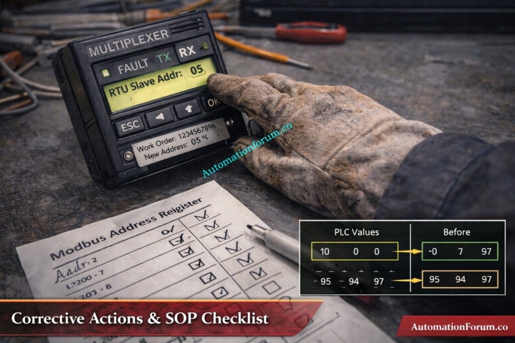
- The engineer changed the spare multiplexer Modbus slave ID to a unique free address using the device front panel, confirmed the new address with the handheld Modbus scanner and verified the device responded singularly at that address.
- Area Two multiplexer was powered back on and the PLC communication diagnostics were observed to confirm CRC errors and timeout counters ceased increasing and normal request response timing resumed.
- Live signal verification was performed for each restored tag: the engineer measured field temperature with a calibrated handheld instrument compared those values to the PLC process variables and recorded the results for every channel to confirm correct mapping and sensor performance.
- Records were updated: the central Modbus address register was modified to include the new assignment device serial number and change date, CMMS work order was completed with attachments and the newly configured devices were labeled with durable address plates.
Control Valve Passing After Overhaul Can Trigger Emergency Shutdown: How to Troubleshoot a Control Valve Passing Problem after Overhauling: Complete Root Cause Analysis
Corrective & Preventive Controls to Implement
Mandatory preinstall Modbus address check and centralized register
- Measure field temperature at transmitter TMP101 using a calibrated thermometer and record 145 degrees Celsius, confirm PLC PV TMP101 reads 145 degrees Celsius at 10 32 and sign verification sheet with technician name and date.
- Repeat the same measurement and comparison for TMP102 through TMP118 recording each field value PLC PV mapping status and noting any discrepancies along with corrective actions taken.
- Monitor each restored tag for a stability period of five minutes and confirm three consecutive consistent readings before final sign off; log any communication retries or CRC events observed during verification for follow up.
- Add screenshots of the PLC trends taken before the removal and after the restoration to the work order. Also, include pictures of the front panel of the device showing the new Modbus ID and the label that was put on it for audit purposes.
PLC Remote I/O Card Failure Can Trip the Entire Plant: Root Cause Analysis of PLC Remote I/O Panel (Point I/O Panel) Cards Failure Issues (Refer below link)
SOP Checklist & Troubleshooting Quick-reference
- Before racking out any field device, get a work permit, double-check the isolation points, and write down the spare serial number in the work order.
- Verify spare Modbus slave ID against the centralized Modbus address register and set the spare to the approved spare ID if necessary before connecting to the live bus.
- If the spare was utilised on a test bench, reset it to the approved spare address, write down the time and date of the bench log entry, and attach the log to the spare record.
- Work with the control room to set up a controlled replacement window. Keep an eye on the PLC trend buffers the whole while the replacement is happening, and take pictures before and after the replacement for incident analysis.
PLC Failure Is One Step Away from Total Production Loss: Common Causes of Programmable Logic Controller(PLC) Failure and Mitigation Strategies
Practical Modbus Scanner and PLC Diagnostics Steps
- Connect the Modbus scanner to the RS485 pair and the common ground. Set the scanner to match the network parameters, such as baud rate, parity, and stop bits. Then, poll the slave IDs one at a time to find unexpected replies.
- Check the scanner output for frames that overlap, frame lengths that don’t match, or repeated responses. Then, export the logs you captured to add to the maintenance record and incident report.
- Check the PLC communication diagnostics for things like CRC error counts, timeout occurrences, retry counters, and request response latency. You may use timestamps to link these metrics to scanner captures and events in the control room.
- If you keep getting the same answers after readdressing capture sample frames serial numbers, you should contact a control systems specialist or vendor support with the proof you have.
SCADA Communication Loss Can Halt Plant Operations Instantly: SCADA Communication Problems and How to Fix Them – A Complete Troubleshooting Guide for Automation Engineers
Preventive Controls and Process Changes to Implement
- Add required Modbus address verification to checklists for replacement and commissioning, and make sure that no spare is linked to the active bus until it has been signed off on. This step must be included in the permit to work closure criteria.
- Maintain a central Modbus address register that includes device tag serial number model assigned address physical location and last updated date and make it accessible to operations maintenance and instrumentation teams.
- Label every addressable device on the front plate inside the enclosure and on the enclosure door showing Modbus ID device tag and last configuration date so field crews can visually confirm settings before installation.
- Set up a bench configuration log system that makes bench engineers write down any temporary address changes and put devices back to an approved spare address before putting them back in inventory. This should be checked by a supervisor.
Incorrect Safety Bypass Can Lead to Audit Failure and Legal Action: IEC 61511 Safety Bypass And Override in Instrumentation and Control System Maintenance
Organizational Rules and Access Control
- Add spare device fields to the CMMS with the spare serial configuration status, the date of the next verification, and reminder alerts so that spares are checked before they are used.
- Do audits every three months to check that the entries in the physical labels register and the CMMS records match up, and fix any problems within a set SLA to keep the register’s integrity.
- Include the incident scenario and reaction actions in regular toolbox discussions and shift handovers so that technicians and operators know what to look for when they see duplicate addresses and implement the isolation procedure right away.
PLC Permissive Logic Failure Can Delay Plant Startup: PLC Permissive Logic Troubleshooting Procedure for Instrumentation Engineers
Example Sop
- Pre replacement verification: verify spare device serial number confirm bench configuration status and Modbus ID against master register, affix a verified address label to the spare and record verification details in the work order.
- Replacement step: under permit to work isolate multiplexer power remove faulty device install spare re-terminate wiring and verify shielding and grounding before restoring power while operations monitors PLC trends.
- Post replacement verification: perform live signal verification for each restored tag, update the Modbus address register and CMMS, attach trend screenshots and device photos to the work order and close the permit with signatures.
Refer the below link for HART Transmitter Diagnostics: What Your Field Device is Telling You
KPI And Monitoring Suggestions After Implementation
- Track mean time to restore for duplicate address incidents and measure the time from alarm escalation to full restoration and verification, with a goal to reduce this interval through process controls and training.
- Keep an eye on how well spare verification procedures are being followed and set a goal percentage of spares that are checked before installation. If they aren’t followed, report it so that remedial action can be taken.
- Check the completion rate and resolution time for quarterly Modbus register audits, and try to fix any inconsistencies within the agreed-upon SLA periods.
- Check the trends in communication problems every month and connect problems that happen more than once to the end of remedial action to make sure that things keep getting better.
Poor Fieldbus Installation Can Destroy Network Reliability: Foundation Fieldbus Installation and Best Practices – Complete Guide for EPC and Maintenance Engineers
Incident Report
Wrong HART Configuration Causes False Readings and Trips: Best Practices for Configuring HART Parameters in DCS Software
Final Actionable Takeaway for Plant Teams
- Treat Modbus address verification as a mandatory preinstall check for any spare device or replacement, and record the verification in the work order to ensure accountability.
- A brief verification step and a durable label on each addressable device will prevent hours of troubleshooting lost production and unnecessary operational risk.
- Incorporate the SOP paragraphs live verification templates and the incident narrative into training and commissioning materials so the whole team recognizes the symptom pattern and follows the correct isolation and verification steps.
Frequently Asked Questions On Duplicate Modbus Address Issues
What is illegal data address error in Modbus?
An illegal data address error occurs when the Modbus master requests a register or coil that does not exist in the slave device.
The slave responds with an exception indicating the requested address is outside its supported memory range.
What is the addressing mode of Modbus?
Modbus uses a master–slave (client–server) addressing mode where each slave device has a unique address.
The master communicates by sending requests to a specific slave address on the network.
What are the weaknesses of Modbus?
What is the standard addressing for Modbus?
Modbus uses logical data areas such as coils, discrete inputs, input registers, and holding registers.
Internally, addressing starts from zero, even though documentation often shows addresses starting from one.
How to configure Modbus address?
What is the maximum device address in Modbus?
In Modbus RTU and ASCII, valid slave addresses range from 1 to 247.
Address 0 is reserved for broadcast messages and cannot be used for individual device communication.