- What is Foundation Fieldbus (FF)?
- Understanding Foundation Fieldbus Architecture
- Foundation Fieldbus Cable Selection Guide
- Foundation Fieldbus Installation Best Practices
- Foundation Fieldbus Cable Preparation and Termination
- Junction Box and Barrier Installation Practices
- Intermediate Junction Box (IJB) Termination and Labeling Rules
- Foundation Fieldbus Earthing and Shielding Guidelines
- Termination and Polarity Checks During Commissioning
- Physical Inspection and Corrosion Prevention
- Foundation Fieldbus Cable Management and Identification
- Common Installation Mistakes to Avoid
- Post-Installation Verification and Testing
- Long-Term Maintenance Recommendations
- Foundation Fieldbus Installation Checklist (Downloadable Excel)
- FAQ on Foundation Fieldbus Installation (2025 Update)
- Test your Knowledge on Foundation Fieldbus Communication Protocol
What is Foundation Fieldbus (FF)?
Foundation Fieldbus (FF) is a strong digital communication technology that is commonly used in process automation to connect smart field instruments, control systems, and junction boxes. FF sends both power and digital transmission across a single pair of wires, which is different from the standard 4-20 mA analog loops.
This below article has a complete installation checklist and best practices for EPC engineers and maintenance teams to follow to make sure that signals are sent reliably, noise is kept to a minimum, and the system stays in good shape over time.
Learn how the FISCO model ensures safety in Fieldbus Intrinsically Safe Concept (FISCO) Model for Foundation Fieldbus H1 and Profibus PA
Understanding Foundation Fieldbus Architecture
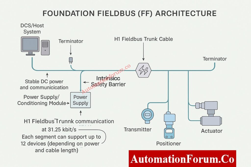
Foundation Fieldbus is a digital system with two wires that runs on a bus at 31.25 kbit/s and is meant for distributed control.
Major Components of an FF Segment
A typical FF segment includes:
- H1 Fieldbus Trunk Cable: Sends and receives data and DC power.
- Spur Connections are short branch wires that link together field devices.
- Terminators: There are two per section, one at the DCS/host end and one at the conclusion.
- Power Supply / Conditioning Module: Keeps the bus voltage steady.
- Junction boxes and barriers keep things separate, safe, and orderly at the ends.
Key Architectural Rules and Device Limits
Depending on the length of the connection and the power budget, one FF segment can support up to 12 devices.
Understand the working principles and features of Foundation Fieldbus H1 Technology
Foundation Fieldbus Cable Selection Guide
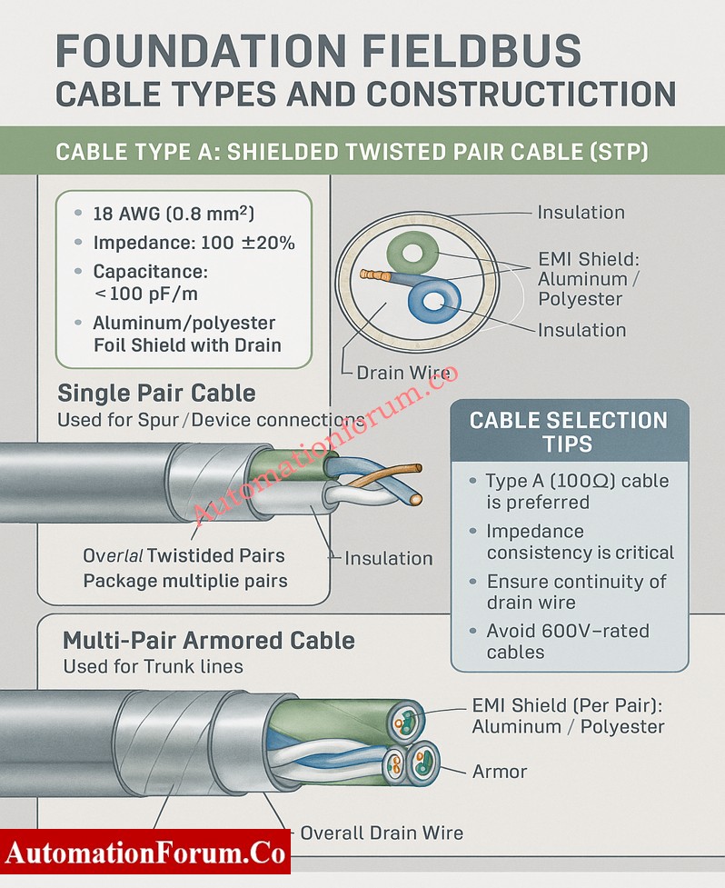
Recommended Cable Type – Type A Shielded Twisted Pair (STP)
- Conductor: 18 AWG (0.8 mm²) for the best signal transmission and the least amount of voltage drop over long distances.
- Impedance: 100 Ω ±20% to keep the signal strong across the network.
- Capacitance: less than 100 pF/m to make sure that signals don’t become distorted and data is sent reliably.
- Shield: Aluminum/polyester foil with a drain wire for better EMI protection and more reliable grounding.
Note: Type B or C cables should only be used for short distances because they make noise and weaken signals.
Cable Construction Options – Single Pair vs Multi-Pair Armored Cable
Single Pair Cable: This type of cable is mostly used to link spur and individual devices.
- Construction: A shielded, twisted pair cable with one drain wire for grounding.
Multi-Pair Armored Cable: Used to connect trunk lines or major segments.
- Construction: Each pair has its own shield, and there is also an overall shield and drain wire for extra safety.
Gain complete insight into the communication layers of Foundation Fieldbus Protocol Basics
Cable Selection Checklist for EPC Engineers
- Always use Type A Foundation Fieldbus (FF) wires for both trunk and spur wiring.
- To stop reflections, keep the impedance the same over the whole section.
- Before you install, make sure the drain wire is still connected and the shielding is still in good shape.
- Don’t use cables that are rated for high voltage (like 600V) in FF circuits because they create unneeded capacitance.
Foundation Fieldbus Installation Best Practices
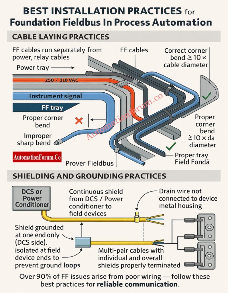
More than 90% of FF communication problems are caused by bad cable preparation or wiring the wrong way. The following best practices will make sure that commissioning goes smoothly.
General Cable Laying Guidelines
- To reduce interference, keep FF wires apart from power, PA, and relay lines.
- Keep at least 300 mm of space between 230/440 V AC cables.
- Follow the rules for separating trays: keep instrument signal trays separate from power trays.
- Don’t put too much stress, twist, or sharp bends on the installation.
- To keep the conductor safe, the minimum bend radius must be at least 10 times the cable diameter.
- To keep impedance stable, never bend the tray corners more than 70 to 110°.
Improve your hazardous area design knowledge using Intrinsic Safety Protection Systems: Understanding Ex ia, Ex ib, and Ex ic
Shield and Ground Management Techniques
- Keep the shield’s integrity intact from the source to the end point.
- Stop the shield at just one end, usually at the DCS or power conditioner end.
- Make sure the shield is isolated at both ends of the device to stop ground loop interference.
- Never connect the drain wire to the metal casing or housing of field equipment.
- Individual and overall shields must stay continuous and correctly terminated for multi-pair cables.
Learn how to differentiate key control elements in Understanding the Difference Between DCS Components: ES, OS, and AS
Foundation Fieldbus Cable Preparation and Termination
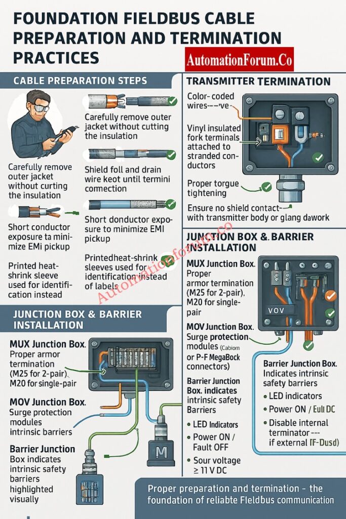
Preparing cables correctly makes sure that signals stay strong and EMI doesn’t get through.
Step-by-Step Cable Preparation Procedure
- Take off the outer jacket gently so that you don’t cut the inside insulation.
- Do not damage the inner insulation or mylar foil when you strip armored cable.
- Don’t cut the shield foil or drain wire until they are attached to the terminal blocks.
- To cut down on electromagnetic pickup, make the exposed conductor as short as possible.
- Use heat shrink tubing (25–40 mm) to cover cuts in the jacket and keep shields separate.
- For long-lasting identification, use printed heat-shrink sleeves instead of sticky labels.
Transmitter Termination and Polarity Verification
- Only take off the jacket length that is needed for gland insertion.
- Orange means positive, and blue is negative.
- Use fork terminals with vinyl insulation for stranded wires.
- Make sure that all terminal screws are tight.
- Make sure the shield doesn’t touch the transmitter body or the gland metalwork.
Discover the core definition and function of What is FOUNDATION Fieldbus ?
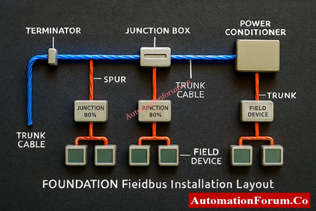
Junction Box and Barrier Installation Practices
MUX Junction Box Termination Procedure
- Used for barrier spur terminations or multiplexer transmitters.
- Use the right armor termination: M25 for 2-pair cables and M20 for single-pair cables.
- Check the accuracy of the trunk input polarity and label.
- Only keep the shield going up to the junction point.
MOV Junction Box for Surge-Protected Applications
- Used in areas that need surge protection or are dangerous.
- Do the same things to get ready as you would for barrier junction boxes.
- Make sure that the trunk and spur ends on Relcom or P+F MegaBlock connectors are right.
Barrier Junction Box (IS/Non-IS) Wiring Steps
- Houses FF boundaries that keep people safe by separating them from each other.
- Each barrier can hold up to four spurs.
- Check the polarity: Orange (+) and Blue (–).
- Check that the LED lights (Power ON, Fault OFF) are on and that the spur voltage is at least 11V DC.
- If you utilize an external TP-32 terminator, turn off the internal terminators.
Intermediate Junction Box (IJB) Termination and Labeling Rules
- It connects marshalling cabinets to field junction boxes.
- Neatly terminate incoming 5-pair trunk cable on indicated terminals.
- Send outgoing single-pair cables to each field section.
- Put spare pairs on terminal blocks that aren’t being utilized right now so you can use them later.
- Keep the trunk and spur shields separate from each other.
- Use ferrules and the right color codes to make it easy to tell which segment is whose.
Compare signal transmission methods and system advantages in Comparison between Conventional (4-20ma) connection, Foundation-Fieldbus, and HART?
Foundation Fieldbus Earthing and Shielding Guidelines
Grounding is important to get rid of noise that comes from outside and make sure that communication works.
Proper Earthing Practices for Noise Reduction
- At the marshalling panel, connect the overall trunk shield to the instrument ground.
- The connector for the FP-32 shield should connect to each segment shield.
- At the IJB, keep the trunk and spur shields separate.
- Make sure that the TP-32 terminator earth is connected to the plant earth grid.
- Check all of the earth points on a regular basis for paint insulation or rust.
- Connect all the FF device earth points directly to the plant instrument earth.
Cable Tray Grounding and Continuity Checks
- Make sure the tray stays together by welding or bolting the seams tightly.
- Fix any joints that are rusted or corroded to keep the grounding safe.
- Don’t use floating trays that cut off the main earth grid from the FF device grounds.
Explore the communication concept and industrial importance of What is Fieldbus?
Termination and Polarity Checks During Commissioning
- Check that all connections are correct (Orange = +, Blue = –).
- Check the polarity of the TP-32 terminator: Red (+) and Black (–).
- Only use two terminators, one at either end of the segment.
- To stop loops, check the shield isolation at the ends of the device. Test the continuity of the drain wire, trunk jumpers, and barrier links.
Physical Inspection and Corrosion Prevention
- Check the inside of JB for moisture, rust, or condensation.
- Use glands with an IP rating to keep anything from getting in.
- Put in breather drains in places where the air is very humid.
- Instead of sharp wire ties, use wide nylon or steel straps.
- To make sure the metal-to-metal contact is solid, clean the earthing lugs and take off any paint.
Follow a step-by-step instrumentation guide on How to calibrate Fieldbus transmitters?
Foundation Fieldbus Cable Management and Identification
- Use heat-shrink coverings to clearly label cables near both ends.
- Keep up-to-date cable schedules and as-built drawings.
- Write down the segment numbers, the locations of the terminators, and the JB references.
- Ground spare trunk pairs correctly to keep noise from getting through.
- Do physical layer tests when you first set up:
- Bus voltage
- Jitter level
- Signal quality index (SQI)
- Retransmission rate
- Error codes
Common Installation Mistakes to Avoid
Do’s and Don’ts Summary
Do’s
- Use regular cable glands and stripping tools.
- Keep the shield going over all parts.
- When routing, make sure to follow the minimum bend radius.
- Check the polarity at either end.
- Use sleeves with printed information.
- Keep the cable trays attached to the ground grid.
Don’ts
- Do not put FF cables and power wires in the same tray.
- Don’t ground shields on both ends.
- Don’t bend wires too much or go beyond the angle limits.
- Don’t let shields stay floating or unconnected.
- Don’t use thin wire ties that will hurt the insulation.
- Don’t forget about corroded tray joints or drifting grounds.
Post-Installation Verification and Testing
Before commissioning each segment:
- Check the voltage on each spur (at least 11 V DC).
- Make sure that terminators are only placed twice for each segment.
- Check that the segment can talk to all of the live-listed devices.
- Use portable Fieldbus diagnostic equipment to record the shape of the signal.
- In the FF installation report, write down the test findings.
Long-Term Maintenance Recommendations
- Every year, check all of the FF junction boxes and cable trays.
- Make that the shield, grounding, and corrosion are all in good shape.
- Use FF diagnostic tools to check the noise levels and signal strength from time to time.
- Keep track of communication issues between devices and fix wiring problems right away.
- Take care of the environmental protection (JB covers and gaskets).
For the system to work well and the signals to stay clear, it is very important to follow the right steps when installing and wiring Foundation Fieldbus.
Engineers can make sure of the following by following this detailed checklist:
- High communication integrity
- Reduced downtime
- Improved diagnostic performance
- Long-term plant safety and reliability
Enhance troubleshooting and diagnostic field skills through Closed-Loop Control Valve Troubleshooting: HART, Fieldbus and Diagnostics Skills Quiz
Foundation Fieldbus Installation Checklist (Downloadable Excel)
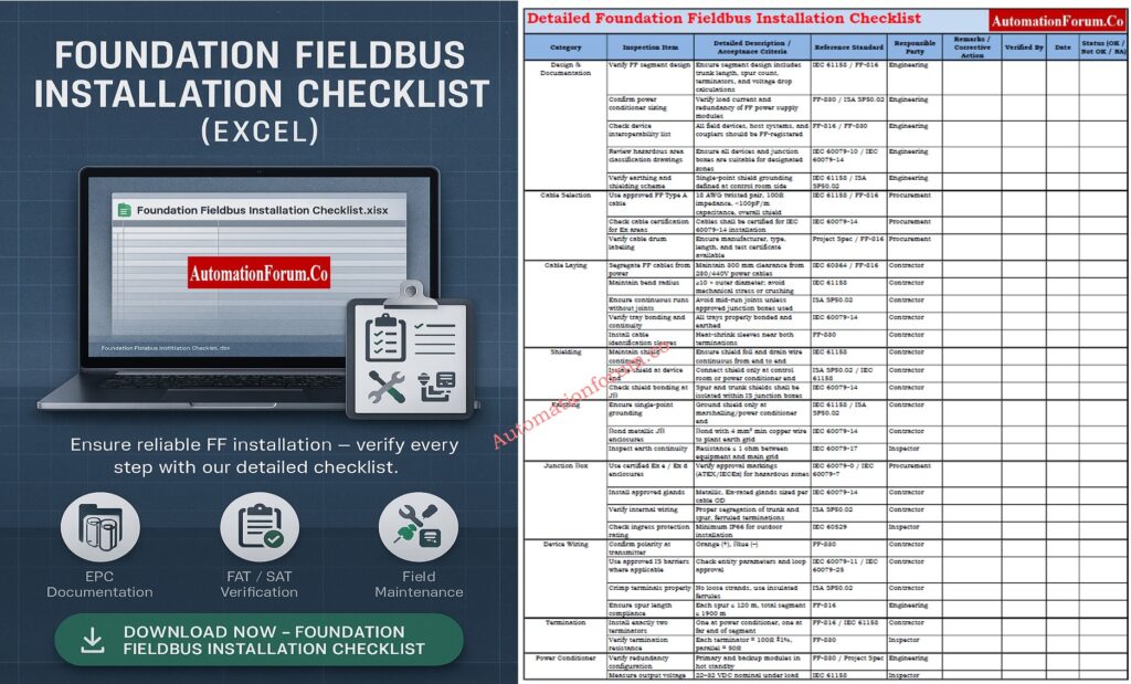
Below is a thorough Foundation Fieldbus Installation Checklist (Excel) that may be used for EPC documentation, FAT/SAT verification, and field maintenance. To download, click the link below.
FAQ on Foundation Fieldbus Installation (2025 Update)
1. What is meant by FOUNDATION Fieldbus?
2. How long is the FOUNDATION Fieldbus cable?
The overall length of the cable for a FOUNDATION Fieldbus H1 segment, including the trunk and all spurs, can be up to 1900 meters.
Depending on the power and network configuration, each spur (the link from the junction box to the device) can be up to 120 meters long.
3. What is FF in instrumentation?
In instrumentation, FF stands for FOUNDATION Fieldbus. It is a digital field communication protocol that links smart field devices to control systems.
4. Does FOUNDATION Fieldbus use 4–20 mA?
No. The standard 4–20 mA analog signal is not used by FOUNDATION Fieldbus.
It sends a digital signal that can send various variables and diagnostic information over the same two wires.
5. What is the distance limit for the FOUNDATION Fieldbus?
Using Type A twisted-pair cable, the usual maximum distance for a FOUNDATION Fieldbus section is 1900 meters.
This limit may be lower in locations that are inherently safe or dangerous, depending on the design of the system and the power source.
6. What is FF in DCS?
In a DCS (Distributed Control System), FF stands for the FOUNDATION Fieldbus network, which connects smart instruments directly to the control system using digital communication.
Test your Knowledge on Foundation Fieldbus Communication Protocol
Test and expand your advanced instrumentation knowledge with Foundation Fieldbus Communication Protocol Advanced Quiz for Instrumentation Engineers