- What is FF transmitter?
- How do you calibrate a pressure transmitter in a field?
- Purpose and Scope:
- Tools required for FF pressure transmitter calibration:
- Safety
- Calibration Setup
- How do you calibrate a FF transmitter?
- Calibration procedure
- Recording calibration
- Completion of calibration
- Sample calibration report
What is FF transmitter?

Fieldbus is a bidirectional communication protocol that enables real-time, closed-loop control between intelligent field devices and host systems. A host may be any software programme, such as a process control, asset management, or safety system at a plant, or a technician’s portable or notebook device. FF is an open standard that enables field devices to handle input/output and control functions. Network topologies including daisy-chain, star, ring, branch, and tree networks are all compatible with Fieldbus.
How do you calibrate a pressure transmitter in a field?
Purpose and Scope:
This procedure gives a full explanation of how to calibrate a foundation fieldbus pressure transmitter in the field using standards.
Tools required for FF pressure transmitter calibration:

- Pressure calibrator
- Foundation field bus communicator
- Standard Multimeter.
- Test leads and probes.
- Tubes and standard fittings
- Necessary hand tools.
- Soft Cloth for cleaning.
Safety
- For specifics on basic safety, general recommendations, and calibrating operations in process industries, please click the link provided below.
Basic Safety and General Considerations for Process Industries Calibration Process
- Inform operator about the unavailability of transmitter measurement while calibration is being performed.
- Ask the DCS / SCADA operator to set the controller in manual mode for the particular control loop and MOS (Maintenance Override Switch )mode for the ESD loop.
- Locate the FF pressure transmitter that has to be calibrated. Check to make sure it’s the right transmitter, and record any relevant data Tag number (e.g., the manufacturer, model number, pressure range, etc.).
- Depending on the kind of system, it may be necessary to depressurize the system before calibrating the FF pressure transmitter.
- When calibrating the FF pressure DP transmitter, make sure there is no pressure or fluid flowing through it.
- Close or remove the pipe that connects the FF pressure transmitter to the process. The transmitter will be isolated from the process as a result, and no fluid will leak out.
- Any pressure that could have been trapped within the transmitter can be released by opening the bleed or vent valves on it.
- Get the relevant information from the transmitter nameplate once the FF pressure transmitter has been isolated.
- Keep in mind that this general method may need to be modified depending on the specific equipment and process region. Always follow any manufacturer instructions and local safety regulations while dealing with FF pressure transmitters or other process equipment.
- Follow all relevant lockout/tagout procedures to prevent an unintended start. Ensure that the FF transmitter is isolated from the process.
Calibration Setup

- The calibration equipment must be placed in a location free from electromagnetic interference and vibrations. Also, the area must be well-lighted and ventilated.
- Gather all of the equipment and tools that are required.
- The tube’s one end should be connected to the output of the pressure calibrator, and its other end should be connected to the pressure port side of the FF pressure transmitter. Verify the connections to make sure they are secure and free of leaks.
- Prepare and examine the 475 field communicator‘s condition for communication and calibration.
How do you calibrate a FF transmitter?
Calibration procedure
- Remove the cover for the wire terminals on the transmitter, and use a multimeter to confirm that the transmitter has a 24 volt supply.
- The top of the 475 Field Communicator has three lead set terminals.
- Each red terminal represents a strong connection for its protocol. Both protocols use the black terminal, which is a common terminal.
- A shutter ensures that only a single pair of terminals are visible at any one moment; see Fig. Several markings show which pair of terminals is for which protocol.

- Connect the 475 Field Communicator anywhere on the bus (segment). This is normally carried out in the field at the device or the fieldbus spur junction box.
- At this point, we will connect the communicator straight into the transmitter, along with the spur cable wire termination.

- Around 12 mA are taken from the fieldbus segment by the 475 Field Communicator. Verify that the power source or barrier on the fieldbus section has the ability to provide this extra current. Connecting the 475 Field Communicator may cause a fieldbus segment’s power supply to go below its maximum capacity, which might result in a loss of communication.
- Activate the 475 Field Communicator by pressing the power button.
- Double-tap the FOUNDATION Fieldbus Application option on the Field Communicator Main Menu.
- Double-tap the Online option on the main menu of the Fieldbus Application.

- The Fieldbus Live Device List appears and shows which device or host is acting as the LAS (Link Active Scheduler).
- After that, check the address list to make sure the transmitter tag number is correct, and choose which one will be calibrated.

- Once the communication is established, you can perform various operations, such as configuring, calibrating, or troubleshooting the FF transmitter, using the 475 communicator.
- Now you need to turn on the pressure calibrator.
- Check the FF pressure transmitter’s datasheet and confirm that the pressure calibrator’s menu is set to the appropriate unit.
- For example, the datasheet and also the comparison and verification with the field communicator indicate that the transmitter range is from 0 to 4 bar.
- By using a pressure calibrator to apply the LRV to 0%, or 0 bar, on the pressure port of the transmitter,
- Then check the transmitter output on the field communicator display; it should show 0 bar.
- If it is not displaying 0 bar, you will need to adjust it from the calibration menu in field communicator using the LRV sensor trim option if necessary.
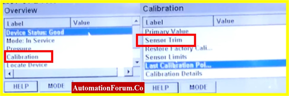
- Now calibrate the URV to 4 bar using a pressure calibrator connected to the pressure port of the transmitter.
- Next, look at the field communicator display to see whether the transmitter output is showing 4 bar.
- If the transmitter output is not showing 4 bar, you must adjust it using the URV sensor trim option from the field communicator’s calibration menu.
- The calibration procedure must be repeated as often as required until the FF pressure transmitter is calibrated to the required tolerance.
- The calibration procedure may vary based on the particular pressure calibrator and FF pressure transmitter being used. Thus, before starting off, make sure you adhere to the manufacturer’s directions.
Recording calibration
- Make sure that the FF pressure transmitter is generating the right output values by performing linearity tests in the upscale and downscale directions at 0%, 25%, 50%, 75%, and 100%.
- Calibration is needed if the output value is outside of an acceptable range. If the output values of an FF pressure transmitter have deviated from the permissible range after the calibration, the transmitter will need to be replaced or repaired.
- If every output value (+/- %) falls within accepted limits, no more calibration is needed.
- The output data should be recorded into the calibration reports as found/as the left column.
Completion of calibration
- The calibration label should be affixed on the FF pressure transmitter after the calibration has been properly performed.
- Disconnect the pressure calibrators, pressure transmitter tube connections, and other setup.
- Clean the test equipment when the calibration is finished, store it safely, and record the calibration data for later use.
- The FF pressure transmitter connections have to be fixed back in the processing area.
- Ensure that the workspace is tidy.
- De-isolate the equipment.
- Set the FF pressure transmitter signal that was bypassed or inhibited back to its initial level.
- Before commencing operation, confirm that the FF pressure transmitter is operating properly.
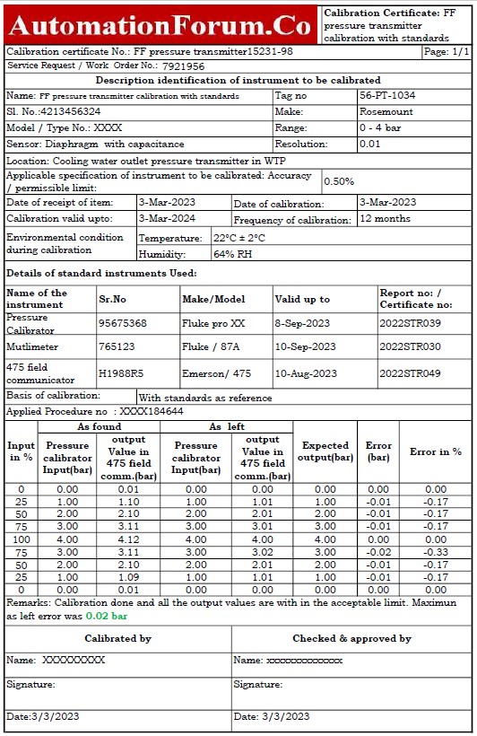
Sample calibration report
The image below demonstrates how the calibration of the FF pressure transmitter sample report was done in a field with the use of a pressure calibrator and a 475 field communicator as a reference.
You may go to the Excel document that was used to make the FF pressure transmitter calibration report by clicking the link below.