
- Why Is My HART Communicator Unable to Detect the Instrument?
- What Is HART Communication and How Does It Work?
- Understanding the HART Communicator Problems: Common indications
- Common Causes of HART Communicator Unable to Detect Instrument
- Incorrect Loop Wiring
- Low Loop Current
- Missing 250 Ohm Loop Resistor
- Loose or Corroded Terminal Connections
- Open Circuit or Damaged Instrument Cable
- Poor Grounding and Electrical Noise
- Incorrect HART Polling Address
- Intrinsic Safety Barrier Compatibility Problems
- Analog Input Card Loading Issues
- HART Communicator and Device Compatibility Problems
- Step by Step HART Communication Troubleshooting Procedure
- Step 1 Verify the Transmitter Power Supply
- Step 2 Inspect the Complete Loop Wiring
- Step 3 Measure the 4–20 mA Loop Current
- Step 4 Verify the 250 Ohm Loop Resistance
- Step 5 Connect the HART Communicator Correctly
- Step 6 Inspect Intrinsic Safety Barriers and Isolators
- Step 7 Verify the HART Polling Address
- Step 8 Test with Another HART Device
- Step 9 Review Device Diagnostic Information
- Step 10 Confirm Successful HART Communication
- Real Field Example of HART Communicator Unable to Detect Instrument
- Engineering Calculations for HART Communication Troubleshooting
- HART Communication Signal Path Explained
- HART Communicator Troubleshooting Table for Common Communication Problems
- Common Mistakes That Cause HART Communication Failure
- Best Practices to Prevent HART Communication Problems
- HART Loop Design Recommendations for Reliable Communication
- International Standards for HART Communication Installation
- Frequently Asked Questions About HART Communicator Communication Problems
- Why is my HART communicator unable to detect the instrument?
- Can HART communication fail while the analog signal still works?
- Why is a 250 ohm resistor required?
- Can electrical noise affect HART communication?
- How to connect a 250 ohm resistor for a HART Communicator?
- What are the disadvantages of HART?
- Why does a HART Communicator need a 250 ohm resistor to connect with a transmitter?
- What is the HART instrument connection?
- What are the disadvantages of HART?
- How do I connect a HART communicator?
- Is HART the same as 4 to 20 mA?
- Why do we use a 250 ohm resistance for HART communication?
- Does every HART transmitter use polling address zero?
- How do I know whether the communicator or transmitter is faulty?
- Can intrinsic safety barriers block HART communication?
- Why should I measure loop voltage during troubleshooting?
- Conclusion: How to Fix HART Communicator Unable to Detect Instrument Errors Quickly
Why Is My HART Communicator Unable to Detect the Instrument?
What Does “No Device Found” Mean?
HART communication has become an essential part of modern process instrumentation because it allows engineers to configure, calibrate, verify, and diagnose smart field devices without interrupting the normal four to twenty milliamp process signal. Whether commissioning a pressure transmitter, troubleshooting a flow meter, or maintaining a control valve positioner, a HART communicator provides quick access to valuable diagnostic information that helps reduce maintenance time and improve plant reliability.
One of the most common field problems is a HART Communicator Unable to Detect Instrument message. Instead of displaying device information, the communicator may report “No Device Found” or “Communication Error.” This situation often occurs during plant commissioning, shutdown activities, routine maintenance, or after replacing a field transmitter.
Common Symptoms of HART Communication Failure
This article describes how HART communication works, why it fails, and the practical troubleshooting procedures that experienced instrumentation engineers employ to reestablish reliable communication in industrial facilities.
Refer th elbow link for the Advanced HART Loop Calculator for Reliable 4 to 20 mA and HART Communication
What Is HART Communication and How Does It Work?

What Is the HART Communication Protocol?
Highway Addressable Remote Transducer, commonly known as HART, is a communication protocol used with smart field instruments. It combines the traditional four to twenty milliamp analog signal with digital communication over the same pair of wires.
How HART Works Over a 4–20 mA Current Loop
The analog current continues to represent the process variable, while the digital signal carries additional information such as device identification, engineering units, calibration data, diagnostics, configuration parameters, and maintenance information.
How Frequency Shift Keying (FSK) Enables HART Communication
HART Frequency Shift A keying technology that transmits digital data as two audio frequencies. Since the average value of these frequencies is zero, the analog current remains unaffected. This allows engineers to communicate with a transmitter while it continues sending the process measurement to the control system.
Compare Popular Instrument Networks Before Choosing Your Next System: Comparison between Conventional (4-20ma) connection, Foundation-Fieldbus, and HART?
Understanding HART Master Slave Communication
Communication follows a master slave principle. The HART communicator acts as the master and the field instrument acts as the slave. The communicator initiates every request, and the device responds with the requested information.
HART Universal Commands and Device Specific Commands
Every HART device supports universal commands such as reading device identification, process variables, and device status. Most instruments also offer general practice commands for configuration and calibration. Manufacturers typically supply device specific commands for advanced diagnostics and maintenance.
HART communication is very reliable and plays an essential role in commissioning, preventative maintenance, calibration and troubleshooting of process instrumentation.
Discover Which Tool Gives Faster Smarter Field Diagnostics Today: SmartBlue vs HART Communicator: Which Is Better for Instrumentation Engineers?
Understanding the HART Communicator Problems: Common indications
If a HART communicator is not detecting the transmitter fault, engineers may see a number of indications.
Common indications include:
- No Device Found
- Communication Error
- No Response from Device
- Failed Polling
- Intermittent Communication
- Wrong Device Information
Interestingly, the analog process value can still be displayed accurately on the DCS or PLC when digital connection fails. This is because HART communication relies on the correct loop resistance, sufficient supply voltage, suitable wiring and compatible communication settings.
The digital HART signal is modest compared to the analog current signal. Any wiring problem, electrical noise, severe loop loading or improper installation can degrade the signal such that communication is impossible.
Knowing what the symptoms are, the engineer may concentrate on the communication loop and not just simply change out the transmitter.
Common Causes of HART Communicator Unable to Detect Instrument

Successful troubleshooting of HART communication requires you to look at the complete communication loop, not just the transmitter.
Incorrect Loop Wiring
Even when the analog signal looks normal, reversed polarity, wrong terminal connections or wiring problems inside junction boxes and marshalling cabinets can disturb the digital transmission.
Always compare the field wiring with the approved loop drawing before replacing any instrument.
Low Loop Current
A HART transmitter requires sufficient loop current for proper operation.
The transmitter electronics may not respond to the communicator due to low current from defective power sources, excessive loop resistance or broken wiring.
Understand Digital Communication Without Getting Lost in Technical Jargon: What is HART Communication Protocol and HART Multiplexer?
Missing 250 Ohm Loop Resistor
A very typical reason for HART communication to fail is the absence of the requisite 250 ohm resistor.
If there isn’t enough loop resistance, the communicator cannot detect the Frequency Shift Keying signal created by the transmitter.
“Just by putting the right resistor in you solve a lot of commissioning problems.
Loose or Corroded Terminal Connections
Loose connections, rusted connectors, broken cable glands, and oxidized terminals raise the electrical resistance and impair the quality of transmission.
When troubleshooting, check each field connection carefully.
Open Circuit or Damaged Instrument Cable
Broken conductors, broken cables, crushed conduit, or moisture inside junction boxes interfere with connection between the transmitter and communicator.
When you troubleshoot, be sure to constantly test for continuity in the cable.
Choose the Right Protection Method for Safer Hazardous Area Loops: Understanding Zener vs Galvanic Isolation in IS Loops for 4 to 20 mA Systems
Poor Grounding and Electrical Noise
Improper cable shielding, many ground points, and close proximity to high voltage equipment can bring electrical noise into the system that can interfere with HART transmission.
Good grounding practices significantly improve communication reliability.
Incorrect HART Polling Address
In point to point applications, the transmitter normally uses polling address zero.
If the device has been configured for multidrop operation, the communicator searching only address zero will fail to detect the instrument.
Always verify the polling address before assuming hardware failure.
Intrinsic Safety Barrier Compatibility Problems
Some intrinsic safety barriers attenuate the HART communication signal if they are not designed for HART compatible operation.
Always verify barrier specifications during hazardous area installations.
Analog Input Card Loading Issues
Some analog input cards present excessive impedance that weakens the digital communication signal.
Temporary connection before the input card or across the loop resistor helps determine whether the control system is affecting communication.
HART Communicator and Device Compatibility Problems
Older communicators may not fully support newer transmitter firmware revisions.
Outdated device description files can also lead to the communicator showing wrong device information.
Regular updating of the communicator software helps to prevent unwanted communication complications.
Avoid Protocol Selection Mistakes That Hurt Process Performance: Difference Between Fieldbus and HART Communication Protocols: Complete Comparison Guide for Process Automation Engineers
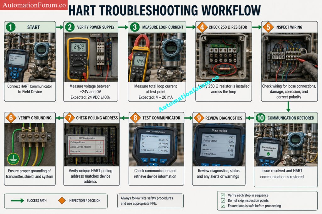
Step by Step HART Communication Troubleshooting Procedure

A organized troubleshooting approach is useful to find the true source of a HART device communication issue quickly and securely.
Step 1 Verify the Transmitter Power Supply
Measure the transmitter supply voltage with a digital multimeter.
Compare the observed value with the minimum operational voltage stated by the manufacturer.
Communication failure is often caused by low supply voltage.
Step 2 Inspect the Complete Loop Wiring
Check inside junction boxes for broken insulation, loose conductors, and dampness.
Step 3 Measure the 4–20 mA Loop Current
Use a calibrated milliamp meter to measure the loop current.
If the current reading is normal, the analog loop is working appropriately. Abnormal current readings can suggest a wiring or transmitter problem.
Step 4 Verify the 250 Ohm Loop Resistance
Measure the total resistance in the loop.
Make sure you have at least two hundred fifty ohms for reliable HART communications.
Install the recommended resistor if needed.
Step 5 Connect the HART Communicator Correctly
Connect the communicator directly across the loop resistor or across the transmitter terminals as indicated by the manufacturer.
Wrong connecting points can block communication.
Step 6 Inspect Intrinsic Safety Barriers and Isolators
Verify the HART communication compatibility of the intrinsic safety barriers, galvanic isolators and surge protection devices.
Replace any incompatible equipment.
Step 7 Verify the HART Polling Address
Verify that the transmitter is set up for point to point or multidrop operation.
If the transmitter address is not zero, modify the communicator’s polling mechanism.
Step 8 Test with Another HART Device
If connection still does not occur, connect the communicator to another known functional transmitter.
Also try the suspect transmitter with another communicator.
Comparing these you may immediately determine if the error is with the communicator or with the field equipment.
Step 9 Review Device Diagnostic Information
Step 10 Confirm Successful HART Communication
Reconnect the loop after corrective operations. Check for stable communication. Check for an accurate process measurement. Document the test results for future maintenance records.
Master Every Critical Variable Behind Accurate Smart Instrument Measurements: Explained: The Four Main Process Variables (PV, SV, TV, QV) in HART Transmitters
Real Field Example of HART Communicator Unable to Detect Instrument
HART Communication Failure During Refinery Commissioning
During the commissioning of a crude oil unit in a refinery, a smart pressure transmitter installed on a pump discharge line could be seen on the DCS with the correct pressure value, but the maintenance engineer received a HART Communicator Unable to Detect Instrument message when attempting configuration.
How a Missing 250 Ohm Resistor Prevented Communication
The transmitter had a twenty four volt DC supply and the loop current measured 11.8 mA, confirming that the analog signal was healthy. Terminal connections inside the junction box were clean and cable continuity was satisfactory. The communicator was also tested on another transmitter and worked normally.
The engineer then measured the voltage across the loop resistor and found that no two hundred fifty ohm resistor had been installed in the marshalling cabinet. During panel assembly, the resistor had been omitted because the analog input card did not require an external resistor for process measurement.
Engineering Solution That Restored HART Communication
After installing the specified resistor, the communicator immediately detected the transmitter. Device configuration, tag verification and loop testing were successfully conducted.
This example shows that a working analog signal does not ensure successful HART communication. Verifying the complete communication path is often more effective than replacing field instruments.
Engineering Calculations for HART Communication Troubleshooting
Practical measurements help engineers identify communication problems quickly.
Loop Current Verification Example
Measured loop current = 12 mA
The transmitter is powered correctly because the current is within the normal operating range.
Voltage Calculation Across the 250 Ohm Resistor
Loop current = 12 mA
Loop resistance = 250 Ω
Voltage = Current × Resistance
Voltage = 0.012 × 250
Voltage = 3 V
A voltage of approximately 3 V across the resistor confirms that the HART communication signal has a suitable path.
Learn the Technology Behind Modern Smart Process Instrumentation Today: What is HART Protocol?
Transmitter Power Supply Margin Calculation
Supply voltage = 24 V
Transmitter minimum operating voltage = 12 V
Available voltage margin = 24 − 12 = 12 V
This margin is generally sufficient to compensate for cable and resistor voltage drops while maintaining reliable communication.
Configure Smart Devices Correctly for Maximum Control System Reliability: Best Practices for Configuring HART Parameters in DCS Software
HART Communication Signal Path Explained
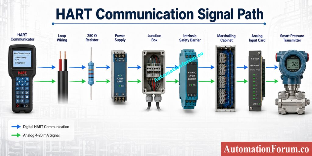
Successful communication depends on every component in the loop operating correctly.
Communication path:
HART Communicator → Loop Wiring → Power Supply → Loop Resistor → Junction Box → Intrinsic Safety Barrier or Isolator → Marshalling Cabinet → Analog Input Card → Smart Transmitter
A failure at any point can interrupt digital communication. During troubleshooting, engineers should verify each section individually instead of assuming the transmitter is faulty.
Prevent Startup Problems with Proven Installation and Commissioning Techniques: Step-by-Step Guide for Installing and Commissioning HART and WirelessHART Devices for Engineers and Technicians
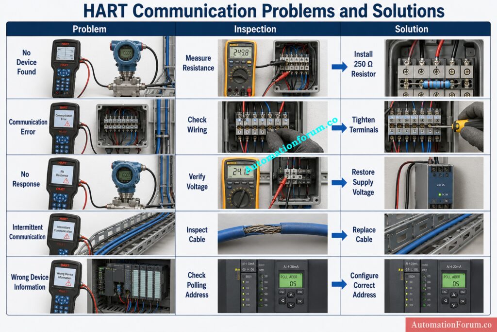
HART Communicator Troubleshooting Table for Common Communication Problems
| Observed Symptom | Possible Cause | Inspection Method | Corrective Action | Expected Result |
| No device found | Missing resistor | Measure loop resistance | Install 250 Ω resistor | Device detected |
| Communication error | Loose terminals | Inspect wiring | Tighten connections | Stable communication |
| No response | Low supply voltage | Measure voltage | Restore power supply | Normal communication |
| Intermittent communication | Moisture or cable damage | Check junction box | Replace damaged cable | Reliable communication |
| Wrong device information | Incorrect polling address | Verify address | Configure correct address | Correct device identified |
Test Your Diagnostic Skills Against Real Industrial Control Challenges: Closed-Loop Control Valve Troubleshooting: HART, Fieldbus and Diagnostics Skills Quiz
Common Mistakes That Cause HART Communication Failure
Several communication problems are created during installation or maintenance rather than by equipment failure.
A common mistake is connecting the communicator across the wrong terminals. You need a two hundred fifty ohm resistor . A common mistake is to neglect to check that it is there before you start troubleshooting .
Some engineers will change transmitters immediately after a communication failure without checking supply voltage, loop current or cable continuity. Others neglect grounding difficulties, electrical noise, or inaccurate device addresses in multidrop systems.
This rigorous, measurement-based approach almost always leads to speedier and more accurate results.
The Small Component That Makes Reliable Digital Communication Possible: Why is a 250-Ohm Resistor Important for HART Communication?
Best Practices to Prevent HART Communication Problems
Reliable maintenance of HART devices begins at commissioning and extends across the plant life cycle.
- Check loop resistance before attaching a communicator. During preventative maintenance, check the field wiring and tighten any loose terminals. Inspect cable insulation, junction boxes and grounding connections periodically for degradation.
- Keep communicator software and device description files current to accommodate newer transmitter revisions. Keep a log of configuration modifications, calibration and communication test results for future reference.
- Shutdowns are the ideal time to perform regular communication checks to uncover problems in the making before they impede production.
Challenge Your Knowledge Before the Next Critical Field Assignment: Advanced HART Protocol Quiz: 25 MCQs with Detailed Explanations
HART Loop Design Recommendations for Reliable Communication
Good engineering design minimizes future communication problems.
- Choose high grade insulated twisted pair cables for industrial applications. Use a common concept for grounding to reduce electrical noise. Size power supply with appropriate voltage margin to compensate for cable losses and devices connected.
- Select HART compliant intrinsic safety barriers and isolators for hazardous area installations. Clearly identify test terminals in marshalling cabinets to ease commissioning and maintenance.
- Maintain a tidy panel wiring, mark all terminals and provide ample space for future growth. Good documentation and easy wiring will reduce maintenance time across the life cycle of the project.
Wire Your Calibration Setup Right the Very First Time: Wiring Diagram for Pressure Transmitter Calibration in Workbench using HART
International Standards for HART Communication Installation
Reliable HART installations are supported by many international standards.
- IEC 61158 and IEC 61784 specify the interoperability requirements and the industrial communication technologies.
- IEC 60079 gives recommendations on electrical equipment used in hazardous situations, including intrinsic safety measures.
- IEC 61511 focuses on the proper management of safety instrumented systems, where reliable field communication supports maintenance tasks.
- IEC 61010 relates to the safe use of electrical test equipment for measurement and troubleshooting.
By following the manufacturer’s installation instructions and accepted industry procedures, you will have safe and dependable communication throughout the instrument’s life cycle.
Prepare for Tough Interviews with Confidence and Technical Accuracy: Understanding WirelessHART: A Comprehensive interview Questions & Answers
Frequently Asked Questions About HART Communicator Communication Problems
Why is my HART communicator unable to detect the instrument?
The most common causes are missing loop resistance, insufficient supply voltage, incorrect wiring, poor terminal connections, or an incorrect polling address.
Can HART communication fail while the analog signal still works?
Yes. The analog four to twenty milliamp signal may be working even when the digital HART signal is not detected.
Why is a 250 ohm resistor required?
The resistor supplies the necessary resistance for reliable Frequency Shift Keying communication between the communicator and the smart instrument.
Can electrical noise affect HART communication?
Yes. Digital communication can be corrupted by bad grounding, bad cable shielding, and neighboring electrical devices.
How to connect a 250 ohm resistor for a HART Communicator?
Connect the 250 ohm resistor in series with the 4 to 20 mA loop, usually across the analog input terminals or in the marshalling cabinet. Connect the HART communicator across the resistor or directly across the transmitter terminals where the HART signal is available.
What are the disadvantages of HART?
With HART the communication speed is limited and thus is less suitable for application where high speed data exchange is required. Proper loop resistance and excellent wiring procedures are also required and may be subject to electrical noise or incompatible interface devices.
Why does a HART Communicator need a 250 ohm resistor to connect with a transmitter?
The 250 ohm resistor provides the minimal loop impedance for the HART Frequency Shift Keying signal to create a detectable voltage. This is called resistance. If there is not enough resistance, the communicator cannot reliably transmit or receive digital communication.
What is the HART instrument connection?
A HART instrument is connected in a standard 4 to 20 mA current loop with a DC power supply, field wiring, and a minimum 250 ohm loop resistance. The HART communicator is connected in parallel across the transmitter or the loop resistor for configuration and diagnostics.
What are the disadvantages of HART?
HART offers limited communication speed and is less suitable for applications requiring high speed data exchange. It also depends on correct loop design and cannot match the performance of modern digital fieldbus or Industrial Ethernet networks.
How do I connect a HART communicator?
Connect the HART communicator across the transmitter terminals or across the 250 ohm loop resistor while the transmitter remains powered. Ensure that the loop has the correct supply voltage and loop resistance before trying communication.
Is HART the same as 4 to 20 mA?
No. The analog process variable is carried on a 4 to 20 mA signal and HART overlays a digital communication signal on the same wires without interfering with the analog measurement. This enables simultaneous process control and device diagnostics.
Why do we use a 250 ohm resistance for HART communication?
A 250 ohm resistor is used to provide the necessary resistance to propagate the HART digital signal across the current loop. This allows the HART communicator to reliably communicate with the smart field instrument and yet keep the conventional analog signal.
Does every HART transmitter use polling address zero?
No. Point to point installations normally use address zero, while multidrop systems assign different addresses to each device.
How do I know whether the communicator or transmitter is faulty?
Test the communicator on another transmitter or connect another communicator to the suspected transmitter. This comparison quickly identifies the faulty component.
Can intrinsic safety barriers block HART communication?
Yes. Some barriers reduce or block digital communication if they are not designed for HART compatible operation.
Why should I measure loop voltage during troubleshooting?
Voltage readings show that the transmitter has enough power to work and transmit properly.
Achieve Accurate Calibration Without Missing Any Essential Field Step: HART transmitter calibration procedure – For pressure transmitter
Conclusion: How to Fix HART Communicator Unable to Detect Instrument Errors Quickly
A HART Communicator Unable to Detect Instrument message is not an automatic sign of a bad transmitter. Communication failures are most commonly caused by wiring faults, inadequate loop resistance, power supply difficulties, bad connections, wrong addressing or incompatible communication components.
The best way to troubleshoot is to check the complete communication loop in a logical order. Before replacing any instrument examine power supply voltage, loop current, resistor presence, field wiring, earth grounding, device address and test with a known functional instrument.
Good commissioning methods, proper documentation, and routine verification of communications and internationally accepted installation standards greatly increase system reliability. A structured engineering approach produces faster restoration of HART communications, reduces maintenance costs, prevents unnecessary equipment replacement, lowers process down time and guarantees that smart field instruments provide reliable diagnostics and precise process measurements throughout their service life.
Refer the below link for the 4-20 mA Loop Troubleshooting with Loop Calibrators : A Practical Guide
