- What is Zener vs Galvanic Isolation in Intrinsic Safety Loops
- What is a Zener Barrier in Intrinsic Safety Systems
- What is a Galvanic Isolator in Intrinsic Safety Applications
- Zener Barrier vs Galvanic Isolator Key Differences Explained
- How to Choose Between Zener Barrier and Galvanic Isolator
- Installation Guidelines for Zener Barriers and Galvanic Isolators
- Commissioning Checklist for Zener Barrier and Galvanic Isolation Systems
- Loop Resistance and Voltage Drop Calculation Example
- Real Industrial Case Studies Zener vs Galvanic Isolation
- Zener vs Galvanic Isolation Quick Comparison Summary
- Best Practices and Engineering Checklist for IS Loop Design
- Frequently Asked Questions Zener vs Galvanic Isolation
What is Zener vs Galvanic Isolation in Intrinsic Safety Loops
Intrinsic safety loops using 4 to 20 mA signals are widely used to keep instrumentation circuits safe in hazardous atmospheres. The choice between a Zener barrier and a galvanic isolator affects grounding practice, available loop voltage, diagnostics, maintenance and long term reliability. This article provides practical selection rules, detailed wiring and installation notes, conservative numerical examples and commissioning checks for instrumentation and control engineers in EPC and operations teams.
Stop IS Loop Failures Now: Top Causes of Intrinsically Safe (IS) Loop Failure and How to Avoid Them
What is a Zener Barrier in Intrinsic Safety Systems
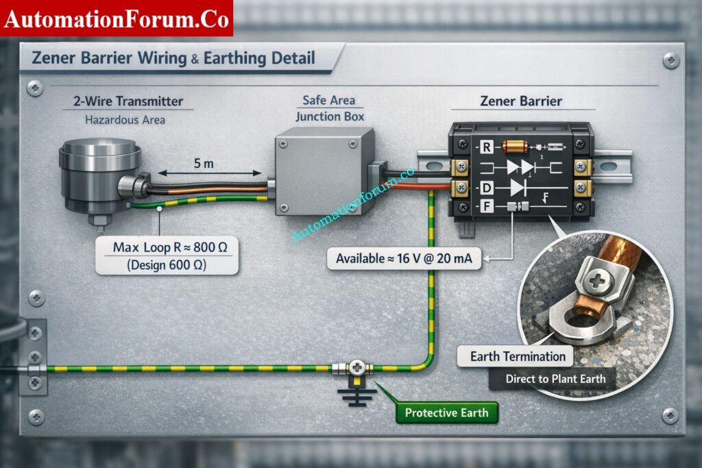
A Zener barrier is an energy limiting device installed in the safe area to prevent energy levels that could ignite a flammable atmosphere from reaching field devices in the hazardous area. The barrier limits both voltage and current using a combination of passive components and a sacrificial fuse.
Read Your Diagnostics Better: HART Transmitter Diagnostics: What Your Field Device is Telling You
How a Zener Barrier Works in 4 to 20 mA IS Loops
A standard Zener barrier consists of:
- a series resistor sized to limit current under fault conditions,
- one or more Zener diodes that clamp voltage to a defined maximum,
- a fuse that opens the feed if a sustained overcurrent occurs,
- a dedicated protective earth connection used to divert clamped energy to ground.
Under normal operation the series resistor and diode network allow the loop to operate and the transmitter to receive sufficient voltage and current. Under a fault such as a short or a power supply failure, the Zener diode clamps voltage and the resistor limits the current to safe levels. If the current remains high long enough, the fuse clears and isolates the circuit.
Zener Barrier Components Resistor Zener Diode Fuse and Earth
There are two practical barrier categories encountered in the field. The first is the low cost passive Zener barrier commonly used on single loop installations. The second is an active barrier where additional electronics reduce voltage drop and provide better defined available voltage to the field device while retaining the Zener clamp and fuse protection. Selection depends on required loop headroom, whether diagnostics and HART communication are required, and the plant earthing policy.
Zener Barrier Grounding Requirements and IS Loop Earthing Rules
The protective earth connection is mandatory for the barrier to perform correctly. If the earth connection is missing, loose, or takes a long path back to plant earth, the barrier may not divert dangerous energy properly. For that reason plant design must specify earth conductor sizing and routing and inspection during commissioning.
Advantages and Limitations of Zener Barriers in Process Plants
- Simple and cost-effective solution for intrinsic safety in basic 4 to 20 mA loops with easy installation and maintenance.
- Requires a reliable low-impedance earth and reduces available loop voltage, which can limit cable length and loop performance.
- Best suited for simple, short-distance applications but less flexible for complex systems, HART communication, and multi-loop setups.
Don’t Confuse Them Again: Difference Between Intrinsically Safe and Explosion-Proof
What is a Galvanic Isolator in Intrinsic Safety Applications
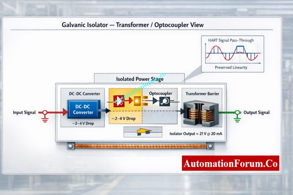
A galvanic isolator provides full electrical separation between the safe area circuit and the hazardous area circuit. Isolation is achieved by means of an isolating transformer, optocoupler or active electronic isolation stage. Isolators are available as loop powered two wire devices and as three port devices that separate input, output and supply.
Refer the below link for the What is SIS, SIF and SIL? An In-Depth Guide to Functional Safety in Process Industries
How Galvanic Isolation Works Using Transformer Optocoupler and Electronics
Common implementations are:
- transformer based isolator where magnetic coupling transfers the signal while blocking dc continuity,
- optocoupler based isolator where light transmits the signal across an insulating barrier,
- active electronic isolator where dedicated circuitry and dc to dc conversion provide isolation and regulated outputs.
Types of Galvanic Isolators Loop Powered and Three Port Isolators
A three port isolator separates the hazardous area loop, the safe area loop and the supply. That architecture allows a safe area earth free installation of the hazardous area side and removes the need to create a dedicated protective earth for safety reasons.
Why 4-20 mA Still Wins: Why Engineers Still Trust the 4-20 mA Signal in Automation Systems
Benefits of Galvanic Isolators for Industrial Instrumentation Systems
Galvanic isolation offers these practical benefits:
- does not require a safety earth on the hazardous area side to perform the energy separation function,
- provides higher available loop volts so long cable runs or higher loop resistance are supported,
- reduces the risk of ground potential differences causing noise or damaging signals,
- often includes built in repeat, conversion or HART passthrough capability which aids diagnostics and integration.
Limitations and Design Considerations of Galvanic Isolators
Isolators are active devices and can be more expensive per channel than a simple Zener barrier. They may require local power or specified loop powering arrangements. For safety certification they must be certified for the intrinsic safety concept in use and installed per manufacturer instructions.
Must Know Before You Design: What is a Safety Barrier? & how does Safety Barrier work?
Zener Barrier vs Galvanic Isolator Key Differences Explained
| Attribute | Zener barrier | Galvanic isolator |
| Principle | Shunt diode clamp with series resistor and fuse | Transformer optocoupler or active isolation stage |
| Components | Resistor Zener diode or diodes fuse earth terminal | Isolation transformer optocoupler or dc to dc converter active electronics |
| Grounding required | Yes a dedicated low impedance protective earth is required | No a safety earth on the hazardous side is not required for isolation function |
| Loop loading | Lower available loop voltage after barrier clamp and resistor | Higher available loop voltage typical lower device voltage drop |
| Typical voltage drop | Variable depending on model may be significant at high currents | Typical device drop 2 to 4 volts dependent on model |
| Frequency and linearity | Adequate for analogue and HART but some units introduce non linear behaviour at extremes | Better linearity and bandwidth often preferred for HART and digital diagnostics |
| Fuse behaviour | Visible fuse opens on sustained fault causing a clear failure mode | No field fuse in isolator electronics faults typically show as open or fail safe on output |
| Reuse and relocation | Cheap per channel but tied to earth wiring and less flexible | More flexible relocatable reusable in different installations |
| Signal conversion | Passive limited to current and voltage limiting | Can provide repeat conversion HART passthrough and signal scaling |
| Typical cost | Lower initial channel cost | Higher initial cost but lower life cycle wiring cost in complex installations |
| When preferred | Simple point to point loops with short runs and reliable plant earth | Long runs multiplexed racks no reliable earth or high accuracy and HART needs |
Learn the Core Concept Fast: What is Intrinsic Safety? Definition, Working Principle, Standards and Applications
How to Choose Between Zener Barrier and Galvanic Isolator
Use the following practical flow to guide selection in intrinsic safety loop design for process plants.
Selection Based on Grounding Availability and Plant Conditions
- Verify plant earth quality and availability before selecting the protection method.
- If a reliable low impedance protective earth is available, a Zener barrier can be used effectively.
- If the earthing is bad or not guaranteed, galvanic isolation is the safer and better option.
Selection Based on Loop Resistance Cable Length and Accuracy
- Check the overall loop resistance and the length of the loop in the 4 to 20 mA circuit.
- Galvanic isolators provide you more voltage headroom and stability for lengthy wire lengths or loops with high resistance.
- Zener barriers can work well for short loops with little resistance.
Verify Your Loop the Right Way: Live Signal Verification 4 to 20 mA Loop Standard Operating Procedure (SOP)
Selection Based on Communication and Diagnostics Requirements
- Figure out if you need HART communication or digital diagnostics in the loop.
- When signal integrity is really important, use galvanic isolators or HART-compatible barriers.
- If you need dependable HART connectivity, don’t use passive Zener barriers.
Selection Based on Maintenance and Future Expansion
- Think about how often the system will need to be changed or added to in the future.
- Galvanic isolators are better for flexible systems since they make it easier to rewire and upgrade them.
- Zener barriers work well for setups that don’t expect many modifications to happen.
Selection Based on Cost Budget and Channel Count
- Check the project’s budget and how many loops need to be installed.
- Zener barriers are a good choice for tiny systems with few channels because they don’t cost much.
- Galvanic isolators may offer better long term value in large or complex installations.
Practical Engineering Decision Approach
- Balance capital cost, operational reliability, and maintenance effort during selection.
- For simple grounded systems, use Zener barriers. For more complicated or important systems, use galvanic isolators.
- This method is in line with standard EPC design practices and the goal of making the plant more reliable over time.
Master Ex ia, Ex ib, Ex ic: Intrinsic Safety Protection Systems: Understanding Ex ia, Ex ib, and Ex ic
Installation Guidelines for Zener Barriers and Galvanic Isolators
To make sure that hazardous area instrumentation systems are safe, reliable, and work well for a long time, it is very important to follow the right installation and wiring rules.
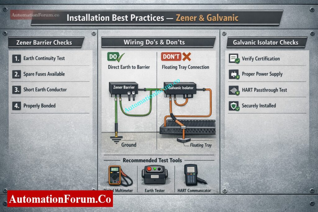
Proper Earthing and Grounding Practices for Zener Barriers
- Connect a separate protected earth conductor from the Zener barrier earth terminal to the plant’s protective earth system. Copper should be used for the earth conductor, and it should be the right size and installed according to plant electrical regulations.
- Make the road to the ground as short and direct as you can. Don’t run the earth wire through panels, structures, or conduits that can create extra impedance and make it less effective.
- Check the earth continuity and make sure the resistance matches the plant’s needs, which is usually less than 1 ohm, during installation and commissioning. Write down the numbers for earth impedance and put them in the commissioning paperwork so you can look them up later.
- To avoid differences and dangerous situations, make sure that all barriers have the same reference ground point.
Cable Routing Shielding and Noise Reduction Techniques
- To stop electromagnetic interference and signal distortion, keep inherent safety cables away from power cables, high voltage lines, and switching circuits.
- Hazardous area wiring guidelines say that cable trays and conduits should have enough space between them. Don’t run high-current wires in parallel across extended distances.
- For sending analog signals over lengthy cable runs, use insulated twisted pair cables. This makes the signal more accurate and less likely to pick up noise.
- Only connect cable shielding at the safe area end, unless the plant’s grounding philosophy says otherwise. Bad shielding can cause ground loops and noise problems.
- Make sure that the documentation for cable identification and routing is correct so that troubleshooting and maintenance can be done.
Installation Best Practices for IS Loops in Hazardous Areas
- Put Zener barriers and galvanic isolators in safe area enclosures like control room cabinets or marshalling panels so they are easy to get to and safe.
- Make sure that the wiring for intrinsic safety and non-intrinsic safety is kept separate inside the panels. Use partitions or separate wiring ducts to keep things separate.
- Make sure to clearly mark all of the loop numbers, barrier terminals, earth connections, and fuse ratings. This makes maintenance easier and troubleshooting faster.
- Follow the manufacturer’s installation instructions exactly, including the polarity of the wire, the torque on the terminals, and the circumstances in the environment.
- Keep your loop diagrams and wiring drawings up to date so that they show how things are actually set up for operational clarity.
Install by the Standard: IEC 60079-14 Explained: Complete Guide to Hazardous Area Installation for Instrumentation and Control Systems
Common Installation Mistakes and How to Avoid Them
- Do not connect Zener barrier earth terminals to local pipework, cable trays, or floating metal structures unless you are sure they are part of the plant’s protective earth system.
- Don’t make more than one earth path for the same barrier system. This can cause currents to flow in a circle, noise problems, and lower intrinsic safety performance.
- Make sure that barrier fuses are not bypassed or replaced with ones that have the wrong ratings. To keep your safety certification, always use the fuse kinds that the manufacturer says to.
- You shouldn’t mix intrinsic safety and non-intrinsic safety wiring without sufficient separation, as this could break hazardous area requirements.
- Check installations often for loose connections, broken wires, or wrong routing to avoid problems with reliability in the long run.
FISCO Explained the Right Way: Fieldbus Intrinsically Safe Concept (FISCO) Model for Foundation Fieldbus H1 and Profibus PA
Commissioning Checklist for Zener Barrier and Galvanic Isolation Systems
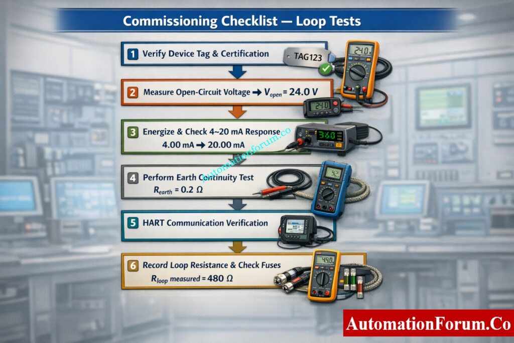
Use this list to make sure that 4 to 20 mA IS loops work safely, follow the rules for intrinsic safety, and send accurate signals.
Step by Step Loop Testing for 4 to 20 mA IS Loops
- Before turning on the device, make sure that the model, certification, and wiring match the loop diagrams.
- Check the open circuit voltage at the transmitter terminals and see how it compares to the values given by the manufacturer.
- Power on the loop, check the 4 to 20 mA signal response, and make sure the control system is working properly.
Don’t Miss These Hazards: What is HAZOP Study in Instrumentation Engineering for EPC Engineers in Process Industries
Earth Continuity Fuse Check and Loop Resistance Testing
- Use a low-ohm meter to check for continuity between the barrier and the plant earth.
- Check the condition of the fuse and make sure it is still connected with the right rating.
- Check the loop resistance at 20 mA and make sure it is within the limitations set by the design.
HART Communication Verification and Signal Validation
- To make sure that a device is who it says it is and that communication is stable, use a HART communicator.
- Make sure that the signal is sent correctly over the entire 4 to 20 mA range.
- Make sure that the barrier or isolator doesn’t change the signal or cause communication to break down
Troubleshooting Common IS Loop Issues
- If the loop isn’t working, look for blown fuses, loose wires, or bad grounding.
- Find problems with high loop resistance or low voltage that are affecting how well the transmitter works.
- Verify cable routing and shielding to eliminate noise and signal instability.
Tools Required for Commissioning
- Digital multimeter and loop calibrator for signal testing.
- Insulation tester and earth tester for wiring and grounding checks.
- HART communicator for diagnostics and calibration.
Avoid Costly Cable Mistakes: Intrinsically Safe Cables for ATEX Zones – Complete Checklist for EPC Engineers
Loop Resistance and Voltage Drop Calculation Example
This example shows how Zener barriers and galvanic isolators affect loop resistance and available voltage in 4 to 20 mA intrinsic safety loops.
Zener Barrier Loop Loading Calculation with Example
- Assume a 24 volt supply and a two wire transmitter operating at 20 mA.
- Available voltage from the Zener barrier is approximately 16.0 volts at full load.
- Maximum loop resistance Rmax = 16.0 divided by 0.02 = 800 ohms, but use a practical design limit of 600 ohms to allow margin.
Galvanic Isolator Loop Loading Calculation with Example
- With a typical isolator voltage drop of 3 volts, about 21 volts is available to the transmitter.
- Maximum loop resistance Rmax = 21 divided by 0.02 = 1050 ohms.
- Use a conservative design limit of around 900 ohms for reliable operation and HART communication.
Practical Design Limits for Long Cable Runs
- Use Zener barriers for short loops with low resistance and stable grounding conditions.
Select galvanic isolators when loop resistance exceeds 600 ohms or cable runs are long. - Always verify calculations using manufacturer data to ensure sufficient voltage margin and loop stability.
Test Your IS Knowledge: Advanced Quiz on Intrinsic Safety Instrumentation Circuits in Oil & Gas Process Industries
Real Industrial Case Studies Zener vs Galvanic Isolation
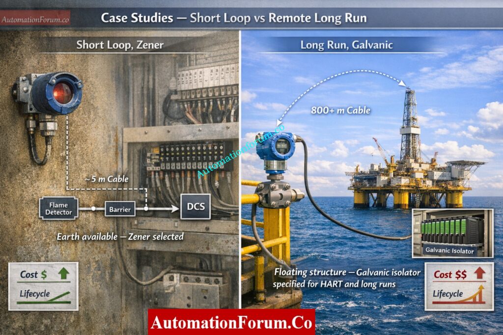
Case Study Zener Barrier for Short Distance Flame Detector Loop
A flame detector in a dusty zone is located five meters from the junction box. The instrument is two wire and requires basic HART diagnostics only occasionally. Plant earth at the control room is robust and short earth conductors can be run to the barrier location. A passive Zener barrier is selected due to low capital cost and ease of local maintenance. The installation includes labeled spare fuses in the local instrument cabinet and a simple commissioning test sheet that includes earth continuity fuse checks and loop resistance measurement. The design limits loop resistance to 500 ohms to preserve HART margin.
Case Study Galvanic Isolator for Remote Transmitter System
A remote transmitter rack sits on a floating platform with no reliable protective earth and cable runs to the control room exceed 800 meters. Multiple 4 to 20 mA loops require HART diagnostics and occasional rerouting. A three port galvanic isolator rack is specified to provide isolation between the hazardous area loops and the safe area I O shelf while allowing HART to pass. The isolator reduces risk from earth loops and gives sufficient loop headroom for long cable resistance. The solution requires higher initial cost but lower maintenance overhead and reduced risk of nuisance tripping or incorrect earthing.
IS vs Non-IS Cables: Difference Between Intrinsically Safe (IS) and Non-IS Cables
Zener vs Galvanic Isolation Quick Comparison Summary
- Zener barrier is simple low cost and relies on a dedicated earth conductor.
- Galvanic isolator provides full electrical separation higher loop headroom and better noise immunity.
- Select Zener when loops are short earth is reliable and budget per channel is constrained.
- Select galvanic isolator when earth is poor runs are long or HART and multiplexing are required.
Do the Calculation Correctly: Intrinsic Safe Calculation for Instrumentation Design Engineers
Best Practices and Engineering Checklist for IS Loop Design
Follow these best practices to ensure reliable, safe, and standards-compliant intrinsic safety loop design in process plants.
Design Checklist for Selecting Safety Barriers
- Evaluate available voltage at 20 mA from vendor data and calculate maximum allowable loop resistance.
- Verify proper earthing requirements and define acceptable earth resistance limits for Zener barrier systems.
- Ensure compatibility with HART communication and other diagnostics if required in the loop design.
Procurement Checklist for Instrumentation Engineers
- Request manufacturer certification to ensure compliance with intrinsic safety standards and IEC 60079 requirements.
- Specify requirements for isolator backplanes in multi-channel systems to simplify wiring and maintenance.
- Include detailed commissioning requirements such as loop voltage verification and earth continuity checks in purchase specifications.
Maintenance Checklist for Long Term Reliability
- Define spare fuse policy and ensure correct rating and accessibility for Zener barrier installations.
- Maintain proper documentation of loop parameters, earth resistance values, and device specifications.
- Ensure periodic inspection of wiring, grounding, and device performance to maintain long-term system reliability.
Install It Without Errors: Installation Checklist for Intrinsically Safe Instrument (Apparatus)
Frequently Asked Questions Zener vs Galvanic Isolation
What is the difference between Zener barrier and galvanic isolators?
A Zener barrier limits voltage and current using diodes and requires a dedicated earth.
A galvanic isolator provides complete electrical isolation without needing an IS ground.
What is the purpose of a galvanic isolator?
It isolates hazardous and safe area circuits to prevent fault energy transfer.
It also improves signal integrity and eliminates ground loop issues.
What is the difference between galvanic isolation and optical isolation?
Galvanic isolation blocks electrical continuity using transformers or capacitive methods.
Optical isolation is a type of galvanic isolation that uses light via optocouplers.
Are galvanic isolators intrinsically safe?
Yes, when certified, they are used as associated apparatus in IS systems.
They limit energy transfer while maintaining isolation between circuits.
How to check galvanic isolation?
Use an insulation tester to verify high resistance between input and output circuits.
Confirm no direct electrical continuity and check isolation voltage ratings.
What is the purpose of a Zener barrier?
It limits voltage and current entering hazardous areas to prevent ignition.
It safely diverts excess energy to earth using Zener diodes and resistors.
Can I mix Zener barriers and galvanic isolators in one installation?
Yes mixing is common. Keep wiring diagrams explicit and ensure each loop follows the installation practices required by the device used.
What is the most common cause of Zener barrier failure in service?
A blown fuse or a poor earth connection are the most common issues. Both are visible faults if regularly inspected.
Redundancy That Saves Plants: Redundant Transmitters Explained: Reliability, Voting Logic and SIL for Instrumentation Engineers
Will a galvanic isolator always allow HART communication?
Not always verify HART passthrough explicitly in the product data and perform a HART test during commissioning.
Does a galvanic isolator remove the need for careful cable routing?
It reduces sensitivity to earth loops but standard cable segregation shielding and routing practice still applies.
How often should barrier fuses be inspected?
Inspect visually during routine maintenance and test as part of periodic loop verification. Replace only with manufacturer specified fuse types.
Why is galvanic isolation preferred in modern plants?
It eliminates dependence on dedicated IS grounding and avoids ground loop noise issues.
It also supports longer cable runs with improved signal stability and accuracy.
Does a Zener barrier affect loop resistance?
Yes, it reduces available loop voltage, limiting maximum allowable resistance.
This can restrict cable length and impact transmitter performance.
Do galvanic isolators support HART communication?
Most modern isolators allow HART signal passthrough without distortion.
Always confirm HART compatibility in the manufacturer datasheet.
Is grounding required for galvanic isolators?
No dedicated IS earth is required for intrinsic safety operation.
However, proper system grounding practices must still be maintained.
What happens if a Zener barrier fuse blows?
The loop becomes open circuit and the field device stops operating.
The fuse must be replaced with the exact specified rating before restoring service.
Refer the below link for the Why Choose Intrinsic Safety (IS) for Hazardous Area Instrumentation?