- Why Safety Instrumented System Design Mistakes Matter in Process Industries
- What Is a Safety Instrumented System (SIS) and Why ISA-84 Matters
- Top Critical Mistakes in Safety Instrumented System Design
- Common SIS Failures and Their Real Industrial Consequences
- Best Practices to Avoid SIS Design Mistakes
- SIS Design Checklist for Engineers
- Expert Tips for EPC Instrumentation and Maintenance Engineers
- Why Lifecycle Thinking Is Essential in SIS Design
- Frequently Asked Questions About Safety Instrumented System Design
Why Safety Instrumented System Design Mistakes Matter in Process Industries
- Safety Instrumented Systems (SIS) are a critical layer of protection in process industries such as oil & gas, petrochemicals, chemicals, refining, and power generation.
- Their main purpose is to detect hazardous process conditions and drive the plant to a safe state before a serious incident occurs.
- Even a well-funded project can fail if the SIS is designed poorly, tested inadequately, or maintained without discipline.
- Safety Instrumented System design mistakes often happen during early engineering, especially when the team treats functional safety as a documentation task instead of a lifecycle activity.
- Standards such as ISA 84 standard guidelines and IEC 61511 SIS design provide a structured framework to reduce risk, improve traceability, and support safe operation.
- Most of the time, the main problem isn’t that there aren’t any standards. It’s that they aren’t being followed well, that different fields aren’t working together well, and that designers and builders are taking shortcuts.
- A single SIS failure can cause damage to equipment, discharge of chemicals into the environment, loss of production, and even death in the worst circumstances.
- That is why engineers must understand both the technical and practical side of SIS design, including SIL verification, proof testing, independence, and lifecycle management.
Safety Instrumented System design flaws are mistakes made when designing, building, or maintaining SIS that make it less effective in stopping dangerous events.
Redundant Transmitters Explained : Redundant Transmitters Explained: Reliability, Voting Logic and SIL for Instrumentation Engineers
What Is a Safety Instrumented System (SIS) and Why ISA-84 Matters
SIS Definition and Basic Function in Process Safety
- A Safety Instrumented System is an independent protective system designed to prevent or mitigate hazardous events.
- It is separate from the basic process control system and is intended to act only when the process moves into an unsafe condition.
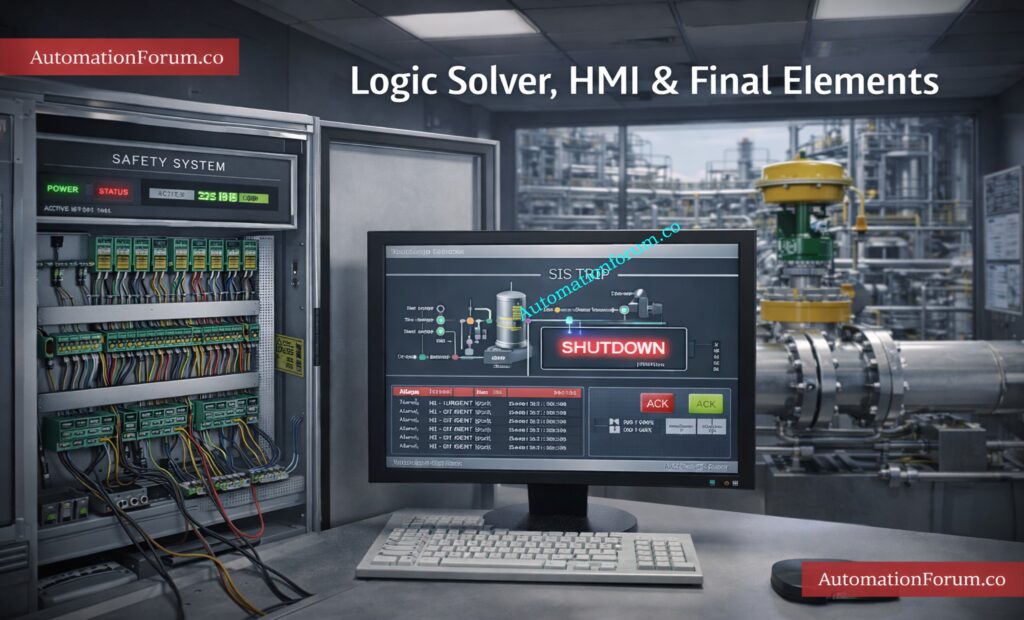
Key Components of SIS:
A typical SIS includes:
- Sensors that detect abnormal process variables
- A logic solver that evaluates the signal and makes the trip decision
- Final elements that bring the plant to a safe condition
The concept of the SIS lifecycle is central to IEC 61511.
Refer the below link for the Emerging and Future Concepts in Functional Safety: AI, Digital Twins and Industry 4.0
SIS Lifecycle as Per IEC 61511
Lifecycle thinking means safety is not handled only during design; it continues through:
- Hazard analysis
- SRS development
- Engineering
- Installation
- Validation
- Operation
- Proof testing
- Modification
- Decommissioning
SIL, or Safety Integrity Level, is one of the most important outputs of the risk assessment process.
Why SIL Is Critical in SIS Design
It defines the level of risk reduction required from the SIS.
Incorrect SIL assignment can lead to:
- Underprotection of the process
- Unnecessary complexity
- High cost without real safety benefit
How ISA-84 Supports Functional Safety Compliance
ISA-84 standard guidelines enforce:
ISA 84 is important because it turns functional safety into a disciplined engineering process rather than an informal design practice.
For instrumentation and control engineers, this means every design choice must be traceable back to risk, operating conditions, and lifecycle requirements.
ESD vs SIS Difference :ESD vs SIS Difference When to Use Each and Practical Engineering Guide
Top Critical Mistakes in Safety Instrumented System Design
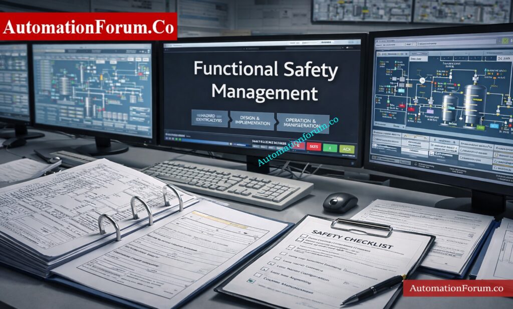
Poor Functional Safety Management (FSM)
Common Issues:
Common symptoms include:
- No formal functional safety plan
- Unclear responsibility between operations, maintenance, engineering, and EPC teams
- Incomplete competency records
- Weak review and approval process
Without FSM, the SIS becomes vulnerable to design gaps, uncontrolled changes, and inconsistent implementation.
In many projects, the design intent is understood by one team, but the installation and maintenance teams never receive the full context.
Real Example:
In a lot of EPC projects, SIS design is outsourced without clear FSM ownership, which leads to SRS that aren’t always the same and designs that don’t match.
How to Avoid:
To avoid this:
- Give each person defined jobs and duties
- Make sure that staff members are schooled in the ideas of functional safety.
- Keep lifecycle records under formal control.
- Do regular safety checks and internal audits
Top 25 SIL MCQs :Top 25 MCQs on Safety Integrity Level (SIL) for Instrumentation and Control Engineers
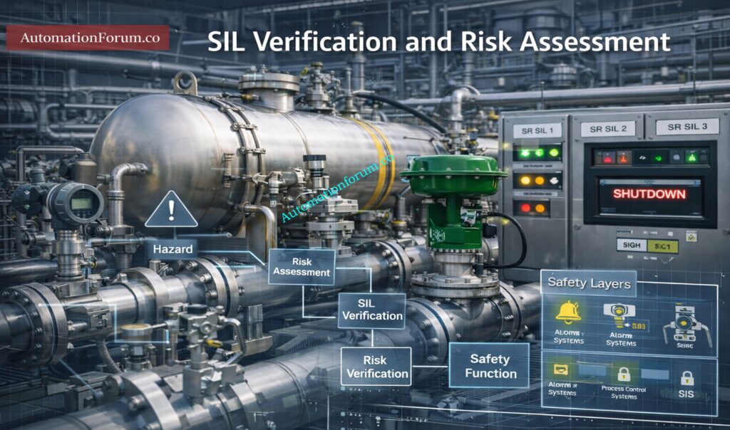
Incorrect SIL Assignment and SIL Verification Errors
When teams rush through the risk assessment stage or depend on assumptions instead of formal analysis, they often make mistakes when calculating SIL.
Common Errors:
Some common mistakes are:
- Studies of HAZOP or LOPA that are not strong
- Taking SIL values from other plants without a good reason
- Not checking that the chosen SIL really does lower the risk as planned
- Doing verification too late, after the equipment choice has already been made
Risks:
Choosing the wrong SIL causes two big problems:
- Underdesign, which means the system doesn’t lower risk enough
- Overdesign, which makes the system hard to maintain and costly
A badly checked SIL can also give people false confidence, which is especially dangerous because it looks like the plant is safe on paper but isn’t in real life.
How to Avoid:
To avoid this:
- Follow a strict methodology for assessing hazards and risks
- Check SIL early on in the design process
- Check the assumptions that were used to figure out the chances of failure
- Check verification again every time the system architecture changes.
Ignoring the SIS Lifecycle Approach
One big reason for SIS lifecycle problems is thinking of SIS as a separate design package.
This happens a lot when safety design, process design, and control design are all done separately.
Common Mistakes:
Some common problems are:
- Not being able to trace from hazard analysis to SRS
- Not having a proof test approach during design
- No thought given to how easy it is to maintain
- Poor preparation for bypasses, overrides, and changes that will happen in the future
Impact:
Without lifecycle thinking, the SIS can work OK at first but stop working over time.
This causes long-term damage, bad audit findings, and trouble proving compliance.
Solution:
To avoid this:
- Connect each safety criterion to a certain risk situation.
- Make sure that design, commissioning, operation, and maintenance are all in sync.
- Don’t only think of the SIS as a project deliverable; think of it as a lifecycle asset.
ESDV Valve Working :What is ESDV (Emergency shutdown Valve)? How ESD valve works?
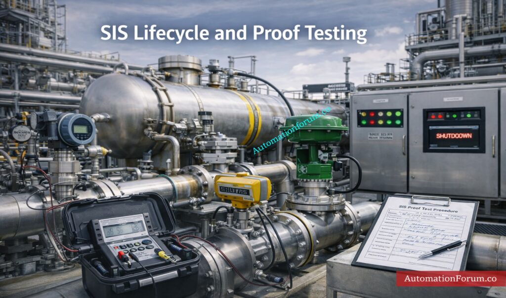
Inadequate SIS Proof Testing and Maintenance
Problems with SIS proof testing are one of the most typical reasons why safety functions don’t work when they should.
Many plants assume that if the system is online and no fault is visible, it is still healthy.
Typical Problems:
Typical mistakes include:
- Proof test intervals that are too long
- Incomplete test procedures
- Testing only a portion of the loop
- Missing bypass control during maintenance
- Not recording found failures correctly
Field Insight:
Poor proof testing reduces confidence in the actual integrity of the loop.
It also weakens the assumptions used in SIL verification.
How to Avoid:
To avoid this:
- Make proof test processes that are based on real risk
- Include the sensors, logic solver, and final pieces in the test scope.
- Teach technicians the specific methods for the exam
- Look for patterns of failure in the test results that happen over and over again.
What is SIS, SIF and SIL? :What is SIS, SIF and SIL? An In-Depth Guide to Functional Safety in Process Industries
Common Cause Failures in SIS Not Addressed Properly
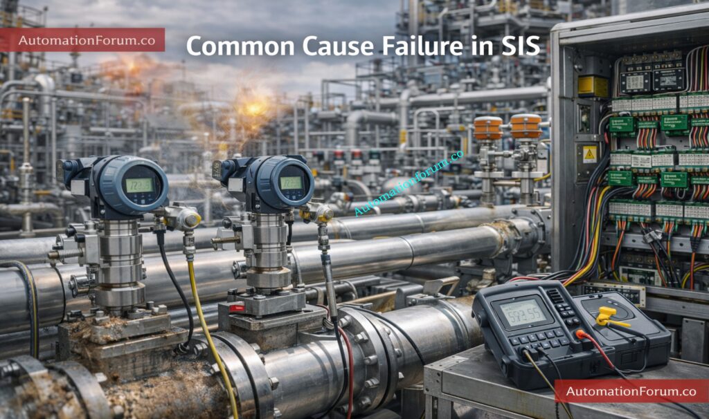
Common cause failure in SIS can make a system that is designed to be safe less safe by breaking redundancy.
This is a frequent oversight in 1oo2, 2oo3, and other redundant architectures.
Examples:
Common sources include:
- Same transmitter technology in all channels
- Same firmware or software defect in redundant logic paths
- Harsh environmental conditions affecting every channel
Calibration Example:
A practical example is calibration error: if all redundant sensors are calibrated using the same incorrect reference or procedure, redundancy does not help.
Another example is using the same devices in the same process environment without taking into account things like vibration, corrosion, or heat that can cause stress.
Prevention:
To avoid this:
- Separate superfluous parts from one another physically
- Think about different technologies when it’s appropriate
- Early on, look at common cause concerns that have to do with the environment and upkeep.
SIF PFDavg / SIL Verification Guide :SIF PFDavg / SIL Verification – Complete Guide + Online Calculator (IEC 61508 / 61511)
Software and SIS Logic Solver Mistakes
It can be hard to find SIS logic solver problems because the system may look right when you do basic testing.
Common Issues:
Things that go wrong a lot are:
- Voting logic
- Trip reset logic
- Bypass handling
- Alarm and permissive conditions
- Sequence dependencies
Real Case:
The wrong logic setup led a high-pressure reactor to trip late, which damaged the equipment.
Common weaknesses include:
- Logic diagrams that weren’t well rated
- Testing of anomalous scenarios that isn’t comprehensive
- Simulation of stopped inputs, broken sensors, or partial trips is not present.
- Unclear handling of manual overrides
The risk is even higher when programmers know how to use regular PLC logic but not how to use safety logic.
Best Practices:
To avoid this:
- Check the logic with your peers
- Check all trip situations during FAT and SAT
- Test not only normal situations, but also abnormal and deteriorating ones.
- Make sure the logic is easy to comprehend, understand, and follow back to the SRS.
Testing and Repair Deferral :Testing and Repair Deferral – IEC Guidelines, Procedure, and Best Practices
Poor Selection of SIS Sensors and Final Elements
A lot of the time, SIS sensor and final element issues start with choosing the wrong device.
Sensors may fail because they are not suitable for the process medium, temperature, pressure, vibration, or corrosion conditions.
Final elements may fail because they are selected like control valves rather than safety shutdown devices.
Common Mistakes:
Common mistakes include:
- Using incompatible wetted materials
- Selecting devices with poor diagnostic coverage
- Ignoring response time requirements
- Installing valves that cannot achieve full shutoff under real plant conditions
Example:
Using standard control valve instead of safety shutdown valve → failure during emergency.
The final element is often the weakest part of the SIS because mechanical devices degrade with wear, contamination, and cycling.
Solution:
To avoid this:
- Verify process compatibility before selection
- Choose devices with proven safety performance
- Consider fail-safe behavior under loss of power or air
- Check maintenance access and replacement practicality
Functional Safety Terminology Excel :Functional Safety Terminology – Excel Download for Industrial Automation
Lack of Independence Between SIS and BPCS
A serious process safety system design mistake is allowing the SIS and BPCS to depend too heavily on each other.
This weakens the protective layer and may violate ISA-84 separation principles.
Issues:
Typical problems include:
Risks:
When independence is lost, one problem can impair both the safety and control functions.
That means that if the fundamental control system fails, the safety shutdown path could also be affected.
Recommendation:
To avoid this:
- Keep safety and control systems separate in terms of both their physical and functional aspects.
- Check dependencies while designing
- Don’t make extra data linkages between SIS and BPCS.
- Make sure the SIS can still work even if the BPCS breaks down.
Signals for Emergency Valve Shutdown :Signals for Emergency Valve Shutdown in Critical Processes
Poor HMI and Alarm Design in Safety Systems
Mistakes in SIS HMI design often make operators confused during important occurrences.
If alerts are not set up correctly, operators may not see the real problem or take action right away.
Common Problems:
Common issues include:
- Flooding alarms during process upset
- Bad alarm prioritization
- Messages that aren’t clear
- Not enough help for responding to emergencies
Consequences:
- Operator confusion
- Late response
The operator should know right away in an emergency:
- What made the trip happen
- What equipment was affected
- What should happen next?
Best Practices:
To avoid this:
- Make safety signs easy to read and understand.
- Use alarm text that means something
- Don’t set off too many annoying alerts.
- Make sure that HMI design fits with what operators need to do.
Signals for Emergency Valve Shutdown :SIF PFDavg / SIL Verification – Complete Guide + Online Calculator (IEC 61508 / 61511)
Weak Documentation and Management of Change (MOC)
One of the most overlooked problems on the SIS audit checklist is poor documentation.
A system could pass commissioning but then fail later because no one can say what was altered.
Common Issues:
Common documentation problems include:
- Outdated loop diagrams
- Missing logic revisions
- No record of bypass history
- Uncontrolled field modifications
Risk:
Changes made during maintenance are not reflected in design documents → unsafe operation.
Without adequate MOC, modifications made while troubleshooting can make things worse.
Solution:
To avoid this:
- Make sure that formal change control is followed
- Keep records up to date throughout their life cycle.
- Check that the as-built documents match the system that was put in place.
- Check all modifications to see how they affect SIL and the integrity of safety functions.
SIS Knowledge Quiz :Test Your Expertise in Safety Instrumented Systems (SIS): Knowledge Quiz
Common SIS Failures and Their Real Industrial Consequences
Safety Incidents and Loss of Containment
Bad SIS design can cause major safety problems, like losing containment, starting a fire, an explosion, or releasing dangerous substances.
SIS Functional Safety Requirements :SIS functional safety requirements
Production Losses and Unplanned Shutdowns
It can also result in:
- Longer plant shutdowns
- Damage to costly spinning or processing equipment
- High expense of maintenance because to recurring failures
Regulatory Non-Compliance and Audit Failures
Findings of non-compliance and regulatory penalties.
Repeated false trips and annoying shutdowns might make operators less confident in the safety mechanism, even when no accident happens.
Risk goes up much more when operators start to ignore or bypass alarms.
2oo2 SOV Working :Understanding 2 out of 2 SOV: Working & Configuration
Case Insight:
Many past events can be traced back to SIS lifecycle errors, like bad maintenance, wrong SIL design, or using the bypass wrong.
That is why common SIS failures should not be seen as separate technical problems, but as problems that happen throughout the entire lifecycle.
Best Practices to Avoid SIS Design Mistakes
- Perform proper hazard and risk analysis before design starts.
- Complete SIL verification early, not after hardware selection.
- Keep the SIS independent from the BPCS.
- Use tools that have been tested and are appropriate for the current process circumstances.
- Make sure you have clear ways to test proof and record failures.
- Teach the engineering, operations, and maintenance teams about their roles in functional safety.
- Check the logic, HMI, and final element behavior when things go wrong.
- Keep detailed lifecycle records and strictly enforce MOC.
Emergency Block Valve :What is an Emergency Block valve and How does it work
SIS Design Checklist for Engineers
| Design Area | Common Mistake | Recommended Practice |
| Functional Safety Management | Unclear roles and weak training | Define responsibilities and competency requirements early |
| Risk Assessment | Weak HAZOP/LOPA or copied SIL values | Base SIL on documented process-specific risk analysis |
| SIL Verification | Late or incomplete verification | Verify SIL during design and revisit after changes |
| Sensors | Wrong material or process compatibility | Select devices suitable for environment and duty |
| Logic Solver | Complex or poorly tested logic | Keep logic simple and validate abnormal scenarios |
| Final Elements | Control valve used as shutdown valve | Use valves and actuators appropriate for safety duty |
| Proof Testing | Incomplete procedures or long intervals | Define full-loop proof tests with clear coverage |
| Independence | Shared systems with BPCS | Maintain separation in hardware, power, and logic |
| HMI / Alarms | Confusing or flooded operator screens | Use clear, prioritized, action-oriented displays |
| Documentation / MOC | Missing revision control | Keep all changes traceable and approved |
Automated Block Valve :What is an Automated Block Valve and how does it work
Expert Tips for EPC Instrumentation and Maintenance Engineers
EPC Design Tips for SIS Engineering
- Check that the SRS is complete before locking down the architecture during EPC design.
- Don’t only trust the values in the catalog; check the vendor’s safety data, diagnostic assumptions, and proof test coverage.
Commissioning Tips for SIS Validation
- When you start up the system, test each trip scenario one at a time. Don’t only trust the factory test findings.
Maintenance Tips for Long-Term SIS Reliability
- Always examine the status of the bypass, the calibration records, and the valve stroke performance during maintenance.
Audit Preparation Tips for SIS Compliance
- During audits, check to see if the system that was actually implemented still meets the design documents that were approved.
- Unless you can show that it won’t, treat any change, even a tiny one, as a possible safety risk.
HIPPS System Working :How does the HIPPS system work in the Oil and gas Industry?
Why Lifecycle Thinking Is Essential in SIS Design
- It’s not enough to only choose safety-rated hardware when designing a reliable SIS.
- It takes focused thinking about the whole life cycle, good management of functional safety, and close attention to how things really are at the facility.
- Most Safety Instrumented System design mistakes come from weak verification, poor proof testing, common cause failures, and missing documentation.
- Engineers who understand ISA 84 standard guidelines and apply them consistently can greatly reduce risk and improve plant reliability.
- A strong SIS is one that works not only during commissioning, but also after years of operation, maintenance, and modification.
- The best way to prevent repeated industry failures is to treat functional safety as an ongoing engineering responsibility, not a one-time project deliverable.
Solenoid Operated Valve (ESD) :Implementing a Solenoid Operated Valve for Emergency Shutdown
Frequently Asked Questions About Safety Instrumented System Design
What are the most common SIS design errors?
Common SIS design errors include incorrect SIL assignment, weak functional safety management, lack of independence from BPCS, and poor proof testing practices.
These issues reduce system reliability and can lead to unsafe conditions during real process upsets.
Why is ISA-84 important for SIS design?
ISA-84 (aligned with IEC 61511) provides a lifecycle-based framework for designing, implementing, and maintaining Safety Instrumented Systems.
It ensures consistent risk reduction, proper documentation, and long-term functional safety compliance.
Voting Logic in SIS :Voting Logic in Safety Instrumented System
What is a common cause failure in SIS?
How often should SIS proof testing be done?
SIS proof testing frequency is defined based on SIL requirements and probability of failure (PFD) calculations.
Intervals must follow the Safety Requirements Specification (SRS) to ensure the system maintains its required integrity.
Emergency Shutdown System (ESD) :What is an Emergency shutdown system and what is its importance?
What is the role of SIL in SIS design?
Safety Integrity Level (SIL) defines the required risk reduction level for each Safety Instrumented Function (SIF).
It ensures the SIS performs reliably enough to meet process safety targets.
What are the final elements in safety instrumented systems?
Final elements are devices that take action to bring the process to a safe state, such as shutdown valves, relays, or motor trips.
They receive signals from the logic solver and physically execute the safety action.
What is the standard for safety instrumented function?
Safety Instrumented Functions (SIFs) are governed by IEC 61511 (process industry) and IEC 61508 (generic functional safety standard).
These standards define requirements for design, SIL assignment, and lifecycle management.
What must a safety instrumented system do?
A Safety Instrumented System must detect hazardous conditions and automatically bring the process to a safe state.
It performs this by sensing, decision-making, and acting through sensors, logic solvers, and final elements.
Refer the below link for Understanding Zener vs Galvanic Isolation in IS Loops for 4 to 20 mA Systems