- Why Fail-Safe Logic Matters in Instrumentation
- Key Terms used in this Explanation:
- Example 1: Non-Fail-Safe Tank Level Monitoring System Using NO Switches (Parallel Logic)
- Example 2: Fail-Safe Level Shutdown Circuit Using NC Switches in Series
- Example 3: Fail-Safe Door Interlock System for Hazardous Process Area
- Summary of Design Differences
- Frequently Asked Questions (FAQ) on Fail-Safe Circuit
- What is a fail-safe circuit?
- What is the concept of fail-safe?
- What is the fail-safe technique?
- What are fail-safe design standards?
- Are fail-safe components normally open or normally closed?
- Test Your Expertise in Safety Instrumented Systems (SIS): Knowledge Quiz
Particularly in safety-critical applications including level control, emergency shutdown, and hazardous process interlocking, fail-safe circuit design is a basic concept in industrial automation and instrumentation systems. Usually to stop or isolate the process, a fail-safe system guarantees that, should a component fail e.g., power loss, wire disconnection, or switch failure the system defaults to a safe situation.
Using real-world examples and circuit diagrams, the article clarifies the ideas of fail-safe against non-fail-safe systems.
Why Fail-Safe Logic Matters in Instrumentation
In industrial uses, a logic circuit must react consistently and safely to abnormal events such as:
- open circuits brought on by wire damage,
- Loss of electricity to sensors or PLCs,
- Mechanical failure of switches or relays.
Generally using normally closed (NC) switches in series, fail-safe logic exploits a loss of signal or power to de-energize the actuator, therefore stopping a pump or a valve.
Key Terms used in this Explanation:
- NO (Normally Open): NO contacts just when the device is turned on.
- NC (Normally Closed): Only contacts open upon activation.
- Contactor/Relay: An electromechanical switch starts and stops motors or pumps among other equipment.
- Fail-safe: A design concept known as “fail-safe” ensures that, should any component fail, the system enters a safe condition.
- Control Relay (CR) and Motor Stop Relay (MSR): Based on logic, Control Relay (CR) and Motor Stop Relay (MSR) help to control the electrical circuit of the motor.
Master the difference between Normally Open and Normally Closed contacts in PLC programming: Understanding NO vs NC Contacts is key for Logic Writing in PLC Programming
Example 1: Non-Fail-Safe Tank Level Monitoring System Using NO Switches (Parallel Logic)
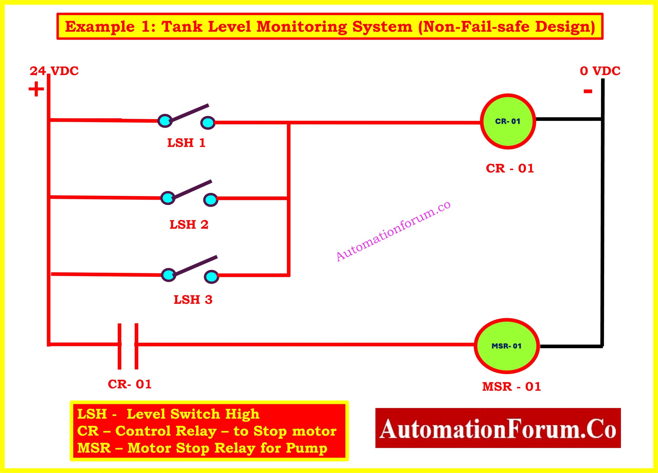
Application: Level switch based overflow protection in a storage tank.
Description:
Three level switches (LSH1, LSH2, LSH3) in this example are connected in parallel and all have normally open (NO) type of creation. Directly connected to a control relay (CR-01), the switches power a motor stop relay (MSR-01), therefore stopping the pump supplying the tank.
How it Works:
- Normal conditions see all switches open and the pump running continuously.
- Should any level switch detect a high level that is, floats up it closes and completes the path from the 24VDC supply to the relay coil (CR-01).
- MSR-01 is triggered and energised by CR-01, therefore stopping the motor.
Weakness in Design (Non-Fail-Safe):
This is a non-fail-safe circuit because:
- This is not a fail-safe circuit as, should any wire connection break shown image below), the relay will never be energized even in case of tank overfills.
- The system assuming the switch or wiring will always be functioning. Should a breakdown occur, the pump runs nonstop, running at the risk of an overflow.
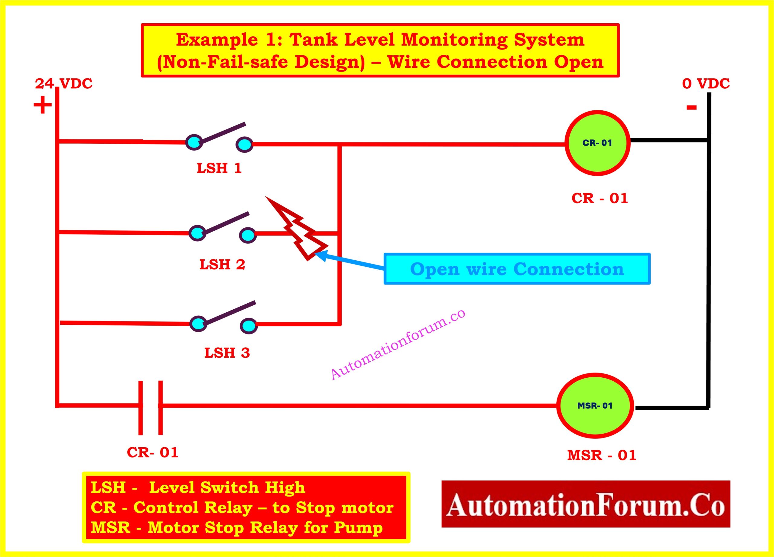
Open Wire Issue:
An open wire ((highlighted in blue) in LSH2 keeps the relay from energizing even if LSH1 or LSH3 finds a high level. Silent failing makes the process potentially hazardous.
Understand the critical signals used to activate ESD valves in safety systems: Signals for Emergency Valve Shutdown in Critical Processes
Example 2: Fail-Safe Level Shutdown Circuit Using NC Switches in Series
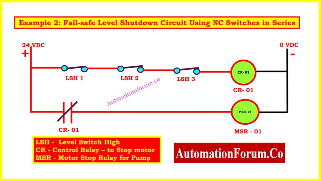
Application: Designed with a fail-safe philosophy, the application is pump cutoff on high-level detection in a sump or tank.
Description:
Three usually closed (NC) level switches (LSH1, LSH2, LSH3) wired in sequence make up this example. The control relay (CR-01) powered by the series circuit energizes MSR-01 to maintain the pump running.
How it Works:
- Under normal level conditions, all NC switches remain closed, and the relay is energized. The motor continues to run.
- If any one of the switches opens due to:High level being reached (actuation), Switch failure, Open wire fault, then the CR-01 gets de-energized, which in turn de-energizes MSR-01 and immediately stopping the motor.
Why this is Fail-Safe:
- The pump will be turned off even from a power outage or a wire failure at any switch.
- It does not rely on a working signal to stop the motor instead, the absence of signal causes a shutdown.
- This approach detects faults by default and acts safely.
Example 3: Fail-Safe Door Interlock System for Hazardous Process Area
Reference Circuit Diagram:
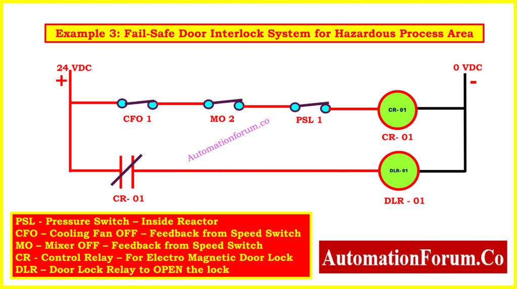
Component Legend:
| Symbol | Label | Description |
| PSL | PSL-1 | Pressure Switch (inside reactor) NC contact used |
| CFO | CFO-1 | Cooling Fan OFF feedback – NC contact from fan’s speed switch |
| MO | MO-2 | Mixer OFF feedback – NC contact from mixer’s speed switch |
| CR | CR-01 | When all conditions are safe, CR-01 Control Relay activates DLR relay. |
| DLR | DLR-01 | Door Lock Relay – opens the electromagnetic lock when energized |
| 24VDC | Power Supply Typical industrial 24VDC control voltage |
Explore why 24VDC is the preferred voltage in industrial automation environments: Why is 24 Volts Mostly used in Industrial PLC Systems?
Working Principle:
Using normally closed (NC) contacts, this series fail-safe circuit addresses all three safety criteria:
- Power Source: When all is safe, the 24VDC supply powers the circuit.
- Safety Chain:
- CFO-1 (Cooling Fan OFF): This switch is closed when the fan is stopped.
- MO-2 (Mixer OFF): This switch is closed when the mixer has fully stopped.
- PSL-1 (Low Pressure): This switch is closed when the pressure is within the safe range.
- All three switches must be closed for CR-01 to be energized.
- Control Relay (CR-01):
- When CR-01 is energized, its auxiliary contact closes and allows current to flow to DLR-01, the Door Lock Relay.
- DLR-01 Function:
- Energizing DLR-01 opens the electromagnetic door lock (fails in the locked position by default).
- This means the door can only be opened when all process parameters are safe.
Learn the foundational elements of Ladder Logic used in PLC programming: Understanding Basic Parts of Ladder Diagram (LD) in PLC Programming
What Happens on Fault or Unsafe Condition?
This is where the fail-safe design comes into play.
| Condition | Result |
| Any one switch (CFO, MO, PSL) opens | CR-01 de-energizes |
| CR-01 de-energized | DLR-01 de-energizes then Electromagnetic lock stays locked |
| Open wire or power failure to any switch | Same as unsafe condition then door stays locked |
| Relay coil failure (CR-01 or DLR-01) | Door remains locked due to loss of energization |
So, even if a wire breaks or a relay fails, the door does NOT unlock, which is the essence of fail-safe behavior.
Key Safety Features of This Design
- Series NC configuration ensures that any one abnormal or failed condition breaks the chain and locks the door.
- All switches are of the fail-to-open type meaning any fault is interpreted as unsafe.
- No single point of failure leads to unsafe access.
- In power outage situations, electromagnetic lock fails to locked position guarantees the area stays safe.
Application Use Cases
- High-pressure vessel in the domains of reactors and furnaces
- Rooms featuring revolving machinery include dryers, mixers, or centrifuges.
- Pharmaceutical Drug or chemical zones needing hazard isolation prior to access.
Summary Table:
| Feature | Description |
| Switch Configuration | NC, wired in series |
| Actuation Logic | All conditions safe then unlock door |
| Fault or Unsafe Condition | Any fault then lock remains engaged |
| Relay Behavior | CR-01 & DLR-01 must both energize to open door |
| Fail-Safe Property | Lock is closed if any component fails |
Summary of Design Differences
| Aspect | Non-Fail-Safe (Example 1) | Fail-Safe (Examples 2 & 3) |
| Switch Type | Normally Open (NO) | Normally Closed (NC) |
| Wiring Arrangement | Parallel | Series |
| Action on Fault | No action unsafe condition | Automatic trip to safe condition |
| Detects Wire Breaks | No | Yes |
| Preferred for Safety Systems | No | Yes |
Designing with a fail-safe approach is not optional for safety-critical operations in industrial automation; it is rather necessary. Systems must be designed assuming that:
- Components can fail,
- Wires may open,
- Power can be lost.
Applying series connections and normally closed logic ensures that any failure sets off a safe action. Fail-safe design provides reliable safety whether you are controlling a motor, valve, door, or other device.
Compare safety, control, and process systems used in modern industrial automation: Understanding Differences of SIS, PLC, and BPCS in Industrial Automation
Frequently Asked Questions (FAQ) on Fail-Safe Circuit
What is a fail-safe circuit?
Designed to create a known and safe output state upon loss, interruption, or invalidation of the input signal, a fail-safe circuit This commonly involves de-energizing outputs like solenoids or relays in industrial systems to bring equipment into a safe condition following failures such power loss, open circuit, or signal dropout.
What is the concept of fail-safe?
The fail-safe idea guarantees that, should a system or device fail, it does so in a way that does not endanger safety, human life, or vital infrastructure. In particular:
- A fail-safe valve closes when power or air supply is lost to prevent chemical leakage.
- A fail-safe interlock keeps hazardous areas locked if process conditions are not safe.
This idea compares with fail-secure systems, in which the focus is on safeguarding data or physical assets usually keeping access limited even during failure.
What is the fail-safe technique?
By means of redundant routes and safety design logic, the fail-safe technique ensures that failure in one component does not cause whole system collapse or hazardous behavior.
For instance, an open circuit (caused by damage) may be simulated by a normally closed (NC) electrical contact, therefore reflecting a fault condition.
Interlock or permissive control systems may default to “deny operation” until all conditions are verified safe.
What are fail-safe design standards?
Standards for fail-safe design demand that systems be built to fail under controlled, non-hazardous conditions. Common in safety-sensitive sectors such chemical plants, nuclear reactors, and aerospace, these criteria apply to
Typical values consist of:
- Use of normally closed circuits or valves
- Inclusion of redundant control paths
- Monitoring of circuit integrity (e.g., open-loop detection)
- Use of de-energize-to-trip logic
Standards include ISO 13849 and IEC 61508 help to facilitate fail-safe design in machine controls and programmable safety systems.
Are fail-safe components normally open or normally closed?
Generally in safety loops especially, fail-safe components are built as normally closed (NC) in their unpowered or unactuated state.
Usually closed, fail-safe valves shut down when either pressure or power is lost.
Usually breaking the circuit (open), fail-safe relays or contacts ensure that, should the system fail, no harmful function proceeds.
Test Your Expertise in Safety Instrumented Systems (SIS): Knowledge Quiz
Refer the below link to test your knowledge on Safety Instrumented Systems (SIS)