In this article, we will see different comparator blocks used in the Siemens TIA Portal. The comparator blocks
The Siemens TIA Portal Comparator blocks are:
- CMP (==) – Compare Equal
- CMP (<>) – Compare Not Equal
- CMP (>=) – Compare Greater than or Equal
- CMP (<=) – Compare Lesser than or Equal
- CMP (>) – Compare Greater than
- CMP (<) – Compare Lesser than
- IN RANGE – Value within Range
- OUT RANGE – Value outside Range
Different Comparator Block of PLC Ladder Logic using in Siemens TIA Portal V16
1.CMP (==) – Compare Equal
2.CMP (<>) – Compare Not Equal
3.CMP (<>) – Compare Not Equal
4.CMP (<=) – Compare Lesser than or Equal
5.CMP (>) – Compare Greater than
6.CMP (<) – Compare Lesser than
7.IN RANGE – Value within Range
8.OUT RANGE – Value outside Range
Declaration of Input and Output of different Comparator PLC block
| COMPARE EQUAL | |||
| S. No | Operation | Input/Output/Others | Address of Each Block |
| 1 | Input Switch_01 | Input | %M0.0 |
| 2 | Count UP Block | UP Counter | %DB1 |
| 3 | Output Load for Input Switch | Output | %Q0.0 |
| 4 | Comparator Equal Block | Compare | %MW0 |
| COMPARE NOT QUAL | |||
| S. No | Operation | Input/Output/Others | Address of Each Block |
| 1 | Input Switch_02 | Input | %M0.1 |
| 2 | Count UP Block | UP Counter | %DB2 |
| 3 | Output Load for Input Switch | Output | %Q0.1 |
| 4 | Comparator Not Equal Block | Compare | %MW1 |
| COMPARE GREATER THAN OR EQUAL | |||
| S. No | Operation | Input/Output/Others | Address of Each Block |
| 1 | Input Switch_03 | Input | %M0.2 |
| 2 | Count UP Block | UP Counter | %DB3 |
| 3 | Output Load for Input Switch | Output | %Q0.2 |
| 4 | Comparator Equal Block | Compare | %MW2 |
| COMPARE LESSER THAN OR EQUAL | |||
| S. No | Operation | Input/Output/Others | Address of Each Block |
| 1 | Input Switch_04 | Input | %M0.3 |
| 2 | Count UP Block | UP Counter | %DB4 |
| 3 | Output Load for Input Switch | Output | %Q0.3 |
| 4 | Comparator Equal Block | Compare | %MW3 |
| COMPARE GREATER THAN | |||
| S. No | Operation | Input/Output/Others | Address of Each Block |
| 1 | Input Switch_05 | Input | %M0.4 |
| 2 | Count UP Block | UP Counter | %DB5 |
| 3 | Output Load for Input Switch | Output | %Q0.4 |
| 4 | Comparator Equal Block | Compare | %MW4 |
| COMPARE LESSER THAN | |||
| S. No | Operation | Input/Output/Others | Address of Each Block |
| 1 | Input Switch_06 | Input | %M0.5 |
| 2 | Count UP Block | UP Counter | %DB6 |
| 3 | Output Load for Input Switch | Output | %Q0.5 |
| 4 | Comparator Equal Block | Compare | %MW5 |
| COMPARE IN RANGE | |||
| S. No | Operation | Input/Output/Others | Address of Each Block |
| 1 | Input Switch_07 | Input | %M0.6 |
| 2 | Count UP Block | UP Counter | %DB1 |
| 3 | Output Load for Input Switch | Output | %Q0.7 |
| 4 | Comparator Equal Block | Compare | %MW6 |
| COMPARE OUT RANGE | |||
| S. No | Operation | Input/Output/Others | Address of Each Block |
| 1 | Input Switch_08 | Input | %M0.7 |
| 2 | Count UP Block | UP Counter | %DB1 |
| 3 | Output Load for Input Switch | Output | %Q1.0 |
| 4 | Comparator Equal Block | Compare | %MW8 |
Different PLC Ladder Logic of Comparator Block Operations
Siemens TIA Portal V16 software is used to develop the PLC program. As stated above, the following Sections explain the various PLC comparator blocks.
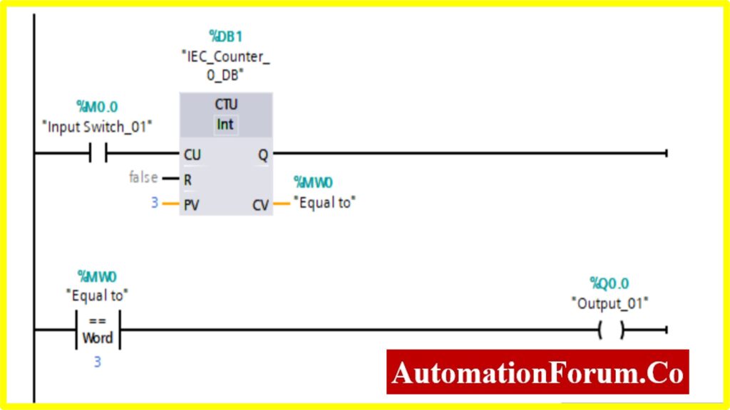
COMPARATOR EQUAL
- The output %Q0.0 will be “Turned ON” if the comparator block connected to the output will be “Turned ON”.
- The Comparator Equal; will be “Turned ON” only if the Register(Memory register) Value %MW0 is equal to the Counter value.
- The Counter will start counting the value with the application of input switch %M0.0.
- Once the Counter value reaches the preset Value. The counter will be “Turned ON”. The comparator will be “Turned ON” once it reaches the specified value. This will“Turn ON” the output.
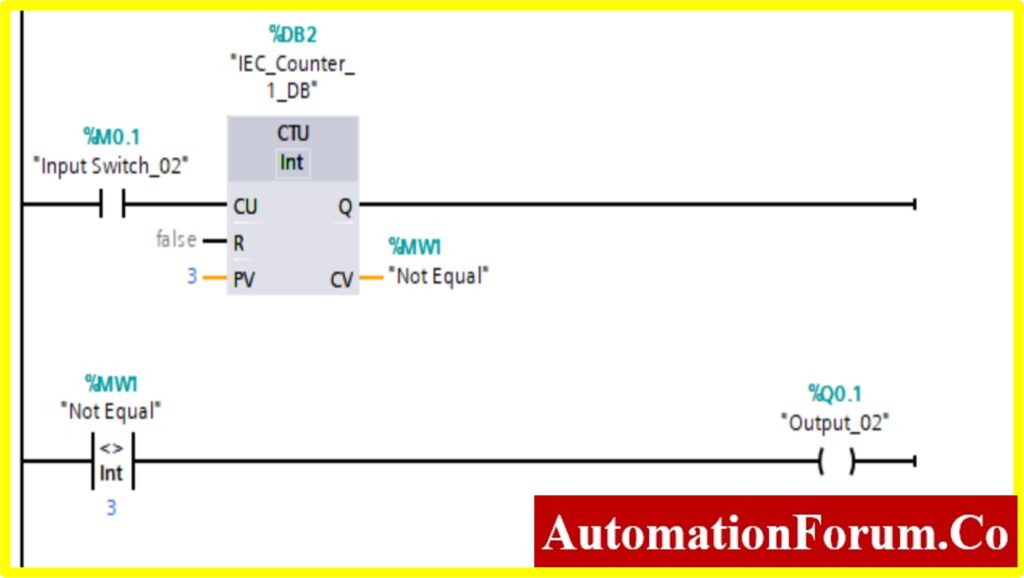
COMPARATOR NOT EQUAL
- The output %Q0.1 will be “Turned ON” if the comparator block connected to the output will be “Turned ON”.
- Until Comparator Not Equal; the output will be “Turned ON” only if the Register (Memory register) Value %MW1 is Not equal to the Counter value.
- The Counter will start counting the value with the application of input switch %M0.1.
- Once the Counter value reaches the preset Value. The counter will be “Turned ON”. The comparator will be “Turned ON” once it reaches the specified value. This will“Turn OFF” the output.
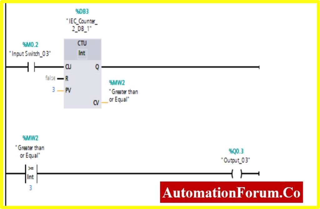
COMPARATOR GREATER THAN OR EQUAL
- The output %Q0.2 will be “Turned ON” if the comparator block connected to the output will be “Turned ON”.
- The Comparator Greater than or Equal; will be “Turned ON” only if the Register (Memory register) Value %MW2 is equal or greater than the Counter value.
- The Counter will start counting the value with the application of input switch %M0.2.
- Once the Counter value reaches the preset Value. The counter will be “Turned ON”. The comparator will be “Turned ON” once it reaches the specified value. This will“Turn ON” the output.
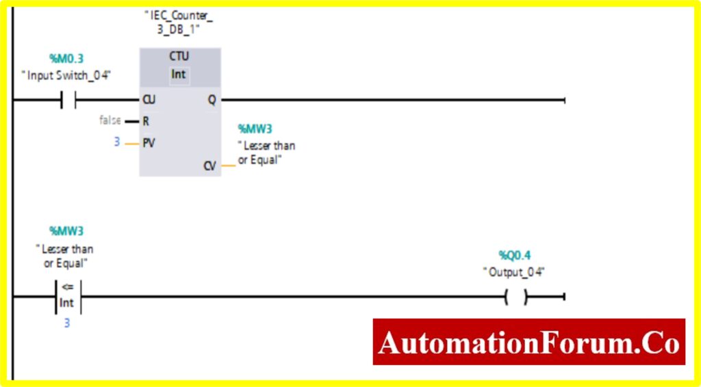
COMPARATOR LESSER THAN OR EQUAL
- The output %Q0.3 will be “Turned ON” if the comparator block connected to the output will be “Turned ON”.
- The Comparator Lesser than or Equal; will be “Turned ON” only if the Register (Memory register) Value %MW3 is equal or lesser than the Counter value.
- The Counter will start counting the value with the application of input switch %M0.3.
- Once the Counter value reaches the preset Value. The counter will be “Turned ON”. The comparator will be “Turned ON” once it reaches the specified value i.e., greater than. This will“Turn OFF” the output.
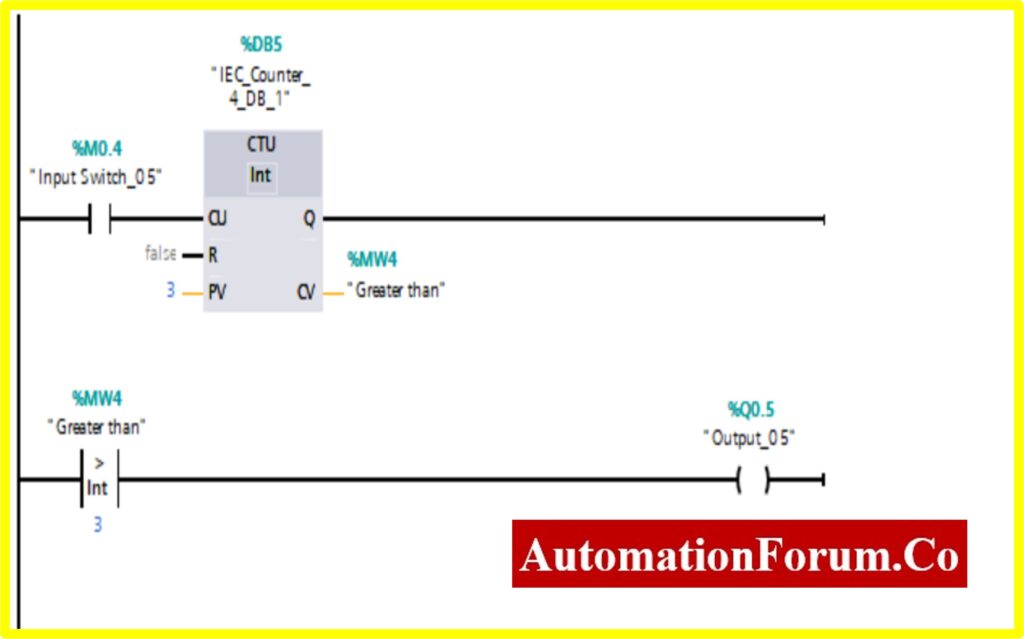
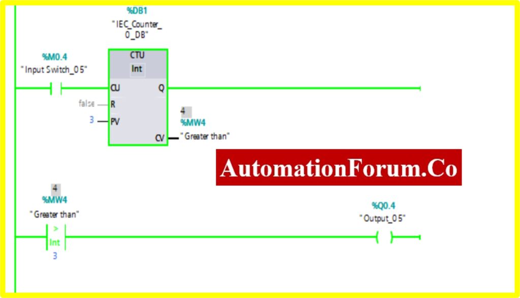
COMPARATOR GREATER THAN
- The output %Q0.4 will be “Turned ON” if the comparator block connected to the output will be “Turned ON”.
- The Comparator Greater than; will be “Turned ON” only if the Register (Memory register) Value %MW4 is greater than the Counter value.
- The Counter will start counting the value with the application of input switch %M0.4.
- Once the Counter value reaches the preset Value. The counter will be “Turned ON”. The comparator will be “Turned ON” once it reaches the specified value. This will“Turn ON” the output.
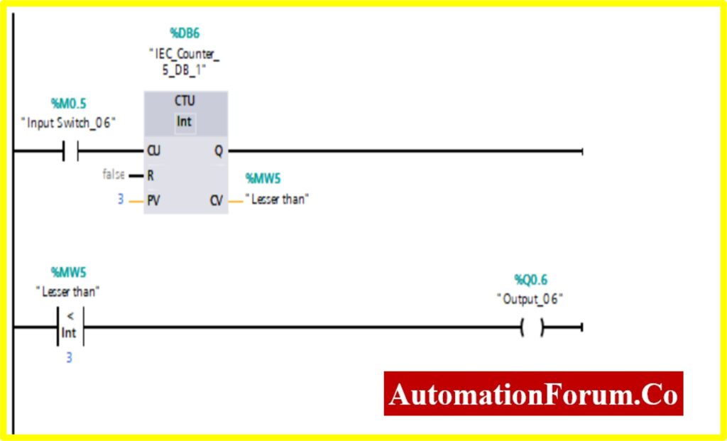
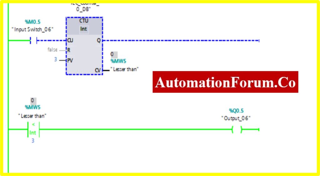
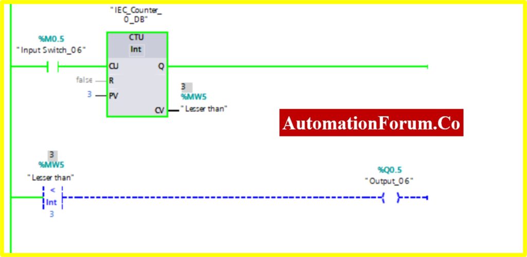
COMPARATOR LESSER THAN
- The output %Q0.5 will be “Turned ON” if the comparator block connected to the output will be “Turned ON”.
- The Comparator Lesser than or Equal; will be “Turned ON” only if the Register (Memory register) Value %MW5 is lesser than the Counter value.
- The Counter will start counting the value with the application of input switch %M0.5.
- Once the Counter value reaches the preset Value. The counter will be “Turned ON”. The comparator will be “Turned ON” once it reaches the specified value i.e., greater than. This will“Turn OFF” the output.
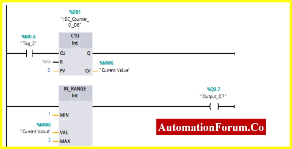
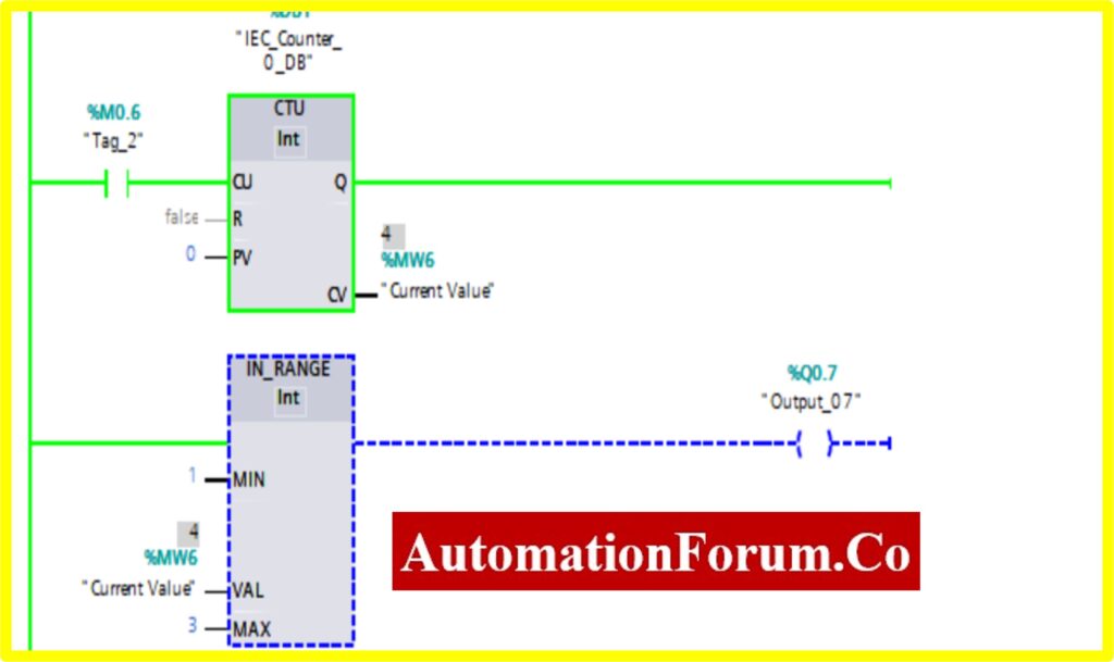
COMPARATOR IN RANGE
- The output %Q0.7 will be “Turned ON” if the comparator block connected to the output will be “Turned ON”.
- The Comparator In Range; will be “Turned ON” only if the Register (Memory register) Value %MW6 within the range of i.e. Min to Max value specified by the Counter value.
- The Counter will start counting the value with the application of input switch %M0.6.
- Once the Counter value reaches the preset range, the counter will be “Turned ON”. The comparator will be “Turned OFF” once the counter value i.e., greater than the specified range.
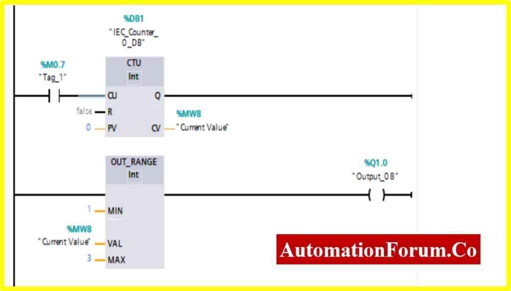
COMPARATOR OUT RANGE
- The output %Q1.0 will be “Turned ON” if the comparator block connected to the output will be “Turned ON”.
- The Comparator Out Range; will be “Turned ON” only if the Register (Memory register) Value is %MW8 Out of the range of i.e., Min to Max value specified by the Counter value.
- The Counter will start counting the value with the application of input switch %M0.7.
- Once the Counter value reaches above the preset range, the counter will be “Turned ON”. The comparator will be “Turned ON” once the counter value reaches the range that is out of specified range.
The steps for programming ladder logic on the SIEMENS TIA website are listed below. (Simulation).
Note: For a detailed explanation of how to use the Siemens TIA Portal to program ladder logic, please refer to the page mentioned above.
Simulation screenshots of different comparator blocks
Below screenshots has been captured for various comparators block when we ran the program in simulation mode in our test laptop
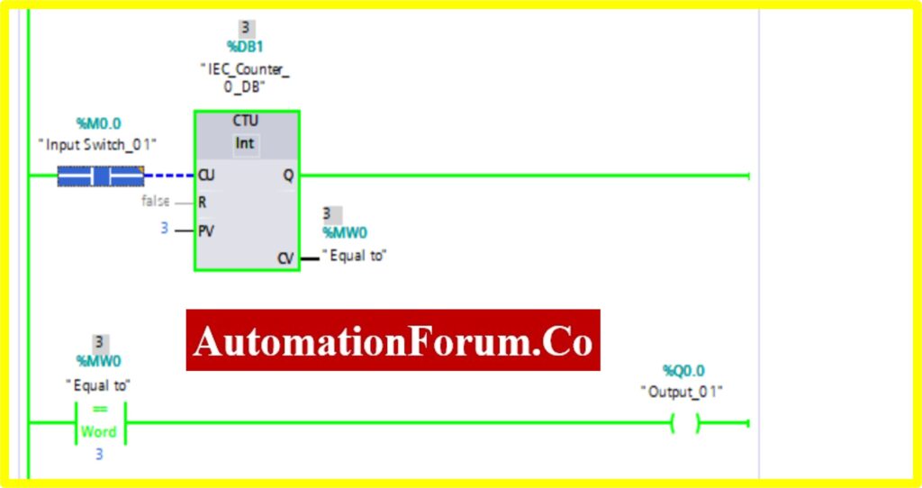
COMPARATOR EQUAL
- The Simulation results show the working of the Comparator Equal Block.
- To understand the Comparator Equal operation Counter block is used.
- The Comparator has two preset values. One is variable another one is registry here %MW0. Once the register value is equal to the variable it “Turns ON” the output.
- The below diagram consists of Input switch_01 %M0.0, which is connected to Up Counter. The Up counter is set with some preset value (Based on our requirement). Current Value(CV) is enabled with register %MW0. The current value continuously increases from every pulse input of the Up counter.
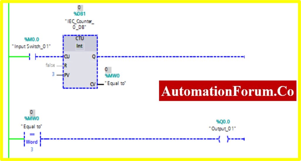
- Once the registry value equals the preset value in the comparator equal block, the Output “Turns ON”.
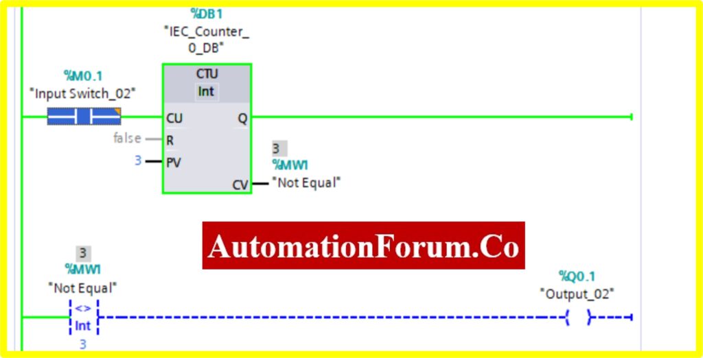
COMPARATOR NOT EQUAL
- The Simulation results show the working of the Comparator is Not Equal Block.
- To understand the Comparator Not Equal Operation Counter block is used.
- The Comparator has two preset values. One is variable another one is registry here %MW1. Once the register value is equal to the variable it “Turns OFF” the output. Until the output is “Turned ON”.
- The below diagram consists of Input switch_02 %M0.1, which is connected to Up Counter. The Up counter is set with some preset value (Based on our requirement). Current Value (CV) is enabled with register %MW1. The current value continuously increases from every pulse input of the Up counter.
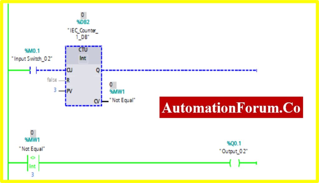
- Once the registry value equals the preset value in the comparator not equal block, the Output “Turns OFF”.
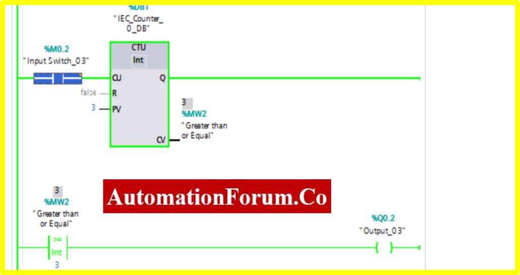
COMPARATOR GREATER THAN OR EQUAL
- The Simulation results show the working of the Comparator Greater than or Equal Block.
- To understand the Comparator Greater than or Equal Operation Counter block is used.
- The Comparator has two preset values. One is variable another one is registry here %MW2. Once the register value is equal or greater to the variable it “Turns ON” the output. Until the output is “Turned OFF”.
- The below diagram consists of Input switch_03 %M0.3, which is connected to Up Counter. The Up counter is set with some preset value (Based on our requirement). Current Value (CV) is enabled with register %MW2. The current value continuously increases from every pulse input of the Up counter.
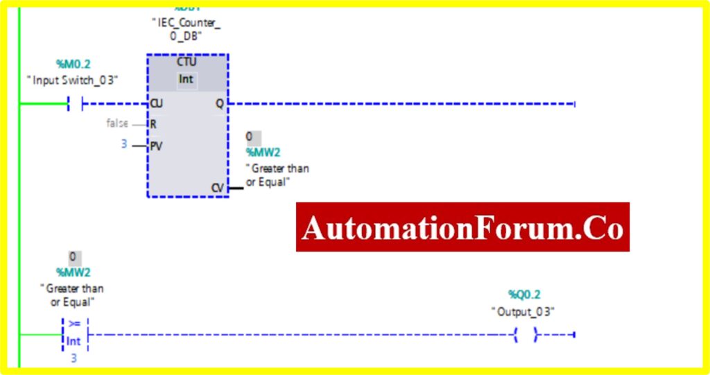
- Once the registry value is equal to the preset value in the comparator equal block, the Output “Turns ON”.
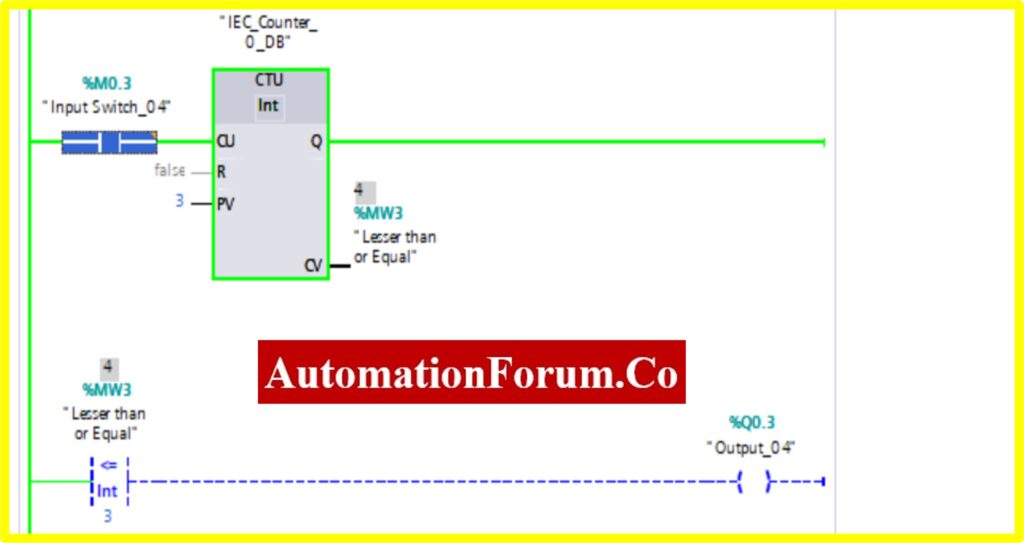
COMPARATOR LESSER THAN OR EQUAL
- The Simulation results show the working of the Comparator Lesser than or Equal Block.
- To understand the Comparator Lesser than or Equal Operation Counter block is used.
- The Comparator has two preset values. One is variable another one is registry here %MW3. Once the register value is equal or lesser to the variable it “Turns OFF” the output. The “Turned ON” output.
- The below diagram consists of Input switch_04 %M0.4, which is connected to Up Counter. The Up counter is set with some preset value (Based on our requirement). Current Value (CV) is enabled with register %MW3. The current value continuously increases from every pulse input of the upcounter.
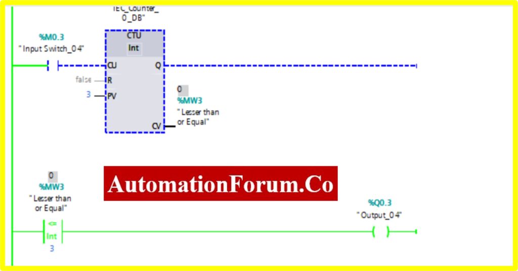
- Once the registry value equals or is greater than the preset value the comparator less than equal block, “Turns OFF” the Output
COMPARATOR GREATER THAN
- The Simulation results show the working of the Comparator Greater than block.
- To understand the Comparator Greater than Operation Counter block is used.
- The Comparator has two preset values. One is variable another one is registry here %MW4. Once the register value is greater than the variable it “Turns ON” the output. The “Turned OFF” output.
- The below diagram consists of Input switch_05 %M0.4, which is connected to Up Counter. The Up counter is set with some preset value (Based on our requirement). Current Value (CV) is enabled with register %MW4. The current value continuously increases from every pulse input of the Up counter
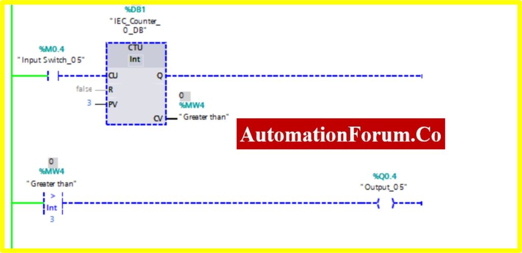
- Once the registry value is greater than the preset value the comparator greater block, “Turns ON” the Output.
COMPARATOR LESSER THAN
- The Simulation results show the working of the Comparator Lesser than Block.
- To understand the Comparator Lesser than the Operation Counter block is used.
- The Comparator has two preset values. One is variable another one is registry here %MW5. Once the register value is greater than the variable it “Turns OFF” the output. The “Turned ON” output.
- The below diagram consists of Input switch_05 %M0.5, which is connected to Up Counter. The Up counter is set with some preset value (Based on our requirement). Current Value (CV) is enabled with register %MW5. The current value continuously increases from every pulse input of the upcounter.
- Once the registry value is greater than the preset value the comparator lesser block, “Turns OFF” the Output.
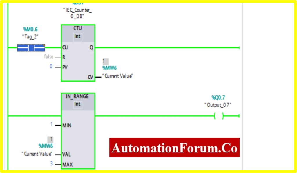
COMPARATOR IN-RANGE
- The Simulation results show the working of the Comparator IN RANGE Block.
- To understand the Comparator IN-RANGE Operation Counter block is used.
- The IN-RANGE Block has three Variable Min, Max, and Val. When the block receives the value between the minimum to maximum set by the current value of Counter. The output is connected to the IN-RANGE block “TURNS ON” the output.
- The below diagram shows the output is “TURNS ON” when the IN-RANGE block receives the current value %MW6 between set by the Counter.
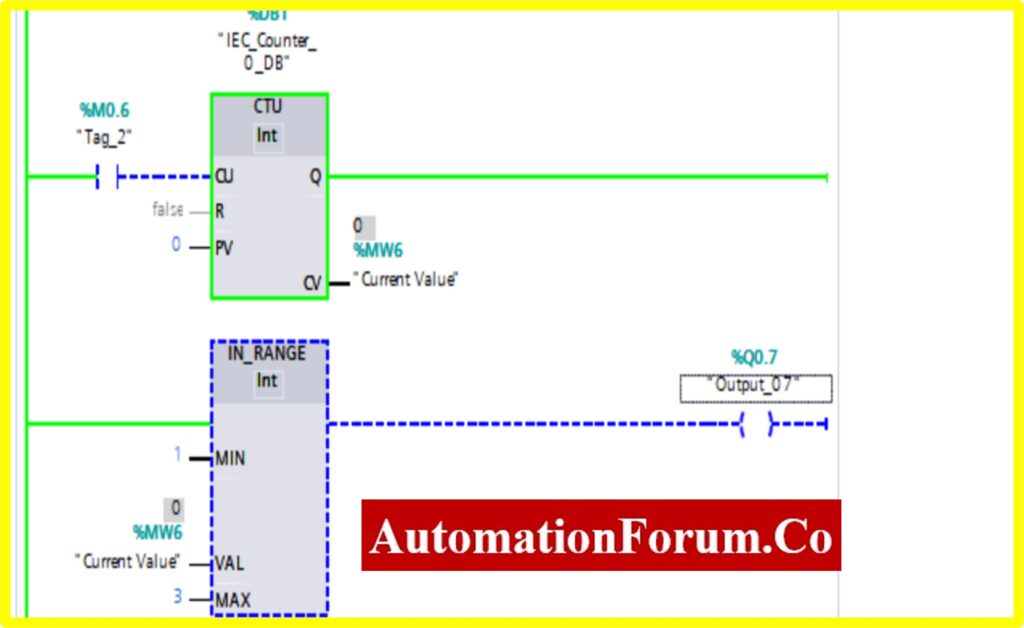
- The Upcounter is enabled by the “Tag_2” of the counter. Once the Upcounter reaches the Current Value (CV) %MW6. The IN-RANGE block “TURNED ON”.
- If the Current Value (CV) %MW6 goes above or out of range. The IN-RANGE block “TURNED OFF”.
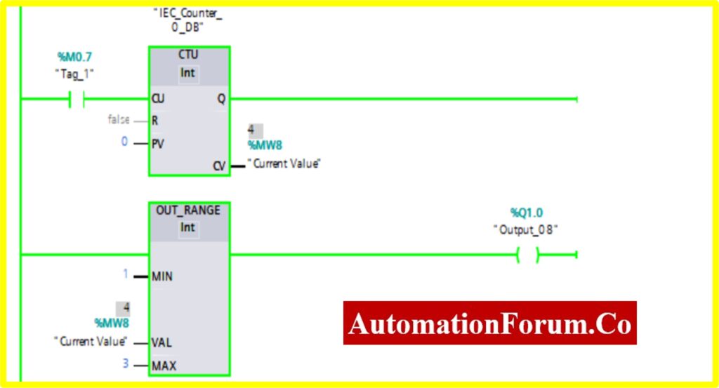
COMPARATOR OUT-RANGE
- The Simulation results show the working of the Comparator OUT RANGE Block.
- To understand the Comparator OUT-RANGE Operation Counter block is used.
- The OUT-RANGE Block has three Variable Min, Max, and Val. When the block receives the value between the minimum to maximum set by the current value of Counter. The output is connected to the OUT-RANGE block “TURNS OFF” the output
- The below diagram shows the output is “TURNS OFF” when the OUT-RANGE block receives the current value %MW7 between set by the Counter.
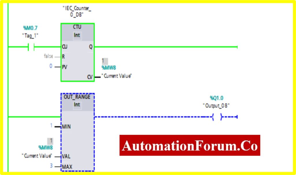
- The Upcounter is enabled by the “Tag_1” of the counter. Once the Upcounter reaches the Current Value (CV) %MW7. The OUT-RANGE block “TURNED ON”.
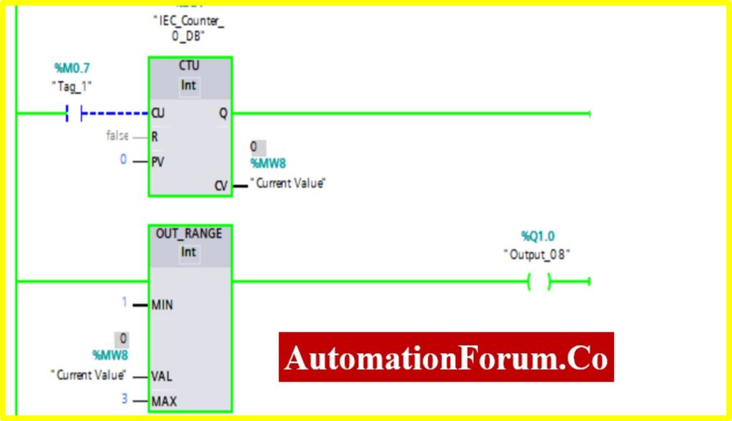
- If the Current Value (CV) %MW7 goes above or below range. The OUT-RANGE block “TURNED ON”
It is possible for the reader to understand the Comparator-logic employed in a PLC by completing the tasks described above.
By following this detailed procedure and explanation, you can gain a comprehensive understanding of how to implement various comparator blocks in PLC ladder logic using Siemens TIA Portal V16. Our engineers tested and verified these logic operations through simulation in the TIA Portal software, ensuring the accuracy and functionality of each comparator block. This step-by-step guide provides valuable insights into the programming and simulation of PLC ladder logic for comparator operations, making it easier for you to apply these concepts in real-world industrial automation scenarios.