- Instrument Earthing and Industrial Grounding Systems
- What is Instrument Earthing in Process Industries
- Overview of the Instrument Earthing Resistance Calculator
- Key Parameters Used in the Instrument Earthing Resistance Calculator
- Who Should Use the Instrument Earthing Resistance Calculator
- How to Use the Instrument Earthing Resistance Calculator Step by Step
- When to Use an Instrument Earthing Resistance Calculator in Process Plants
- Where Instrument Earthing Calculators are Used in Industrial Facilities
- Practical Engineering Tips to Achieve Low Ground Resistance in Industrial Plants
- Importance of Proper Instrument Grounding in Process Industries
- FAQs for Instrument Earthing Resistance Calculator
Power Tools & Solutions
R_total = R / √n
Grounding Targets
- < 1 Ω — Excellent
- 1–2 Ω — Acceptable
- 2–5 Ω — Needs improvement
- > 5 Ω — Poor / remediate
Standards Applied
- IEEE 80 — Substation grounding
- IEEE 142 — Green Book
- IEC 60364 — LV installations
- ISA RP12.6 — Instrument ground
PLC / Instrument
- PLC chassis — < 1 Ω
- DCS cabinets — < 1 Ω
- Signal ground — < 5 Ω
- HART / 4-20 mA — < 2 Ω
Instrument Earthing and Industrial Grounding Systems
Proper instrument earthing is one of the most important foundations of a reliable industrial automation system. In process industries such as oil and gas, petrochemical plants, refineries, power plants, and water treatment facilities, thousands of instruments and control systems depend on stable electrical grounding to function accurately and safely.
When the earthing system is poorly designed or has high resistance, several operational problems can occur. Engineers frequently encounter PLC communication failures, unstable 4 to 20 mA signals, instrument drift, erratic alarms in control systems, and potential damage to delicate equipment during lightning strikes or electrical surges. Not only are these problems hard to fix, but they can also cause expensive production delays.
Correct industrial grounding makes sure that electrical noise is securely sent to the ground and gives instrumentation signals a solid reference point. This is particularly critical for PLC grounding systems, distributed control systems, analyzers, and field instruments.
An Instrument Earthing Resistance Calculator is a practical engineering tool that helps engineers estimate the resistance of grounding electrodes before installation. By performing a quick earthing resistance calculation using soil properties and ground rod parameters, engineers can design an effective industrial earthing system that meets process plant grounding requirements and improves overall automation reliability.
Fix SCADA Communication Problems Fast: SCADA Communication Problems and How to Fix Them – A Complete Troubleshooting Guide
What is Instrument Earthing in Process Industries
Importance of Instrument Grounding in Industrial Automation Systems
Instrument earthing refers to the practice of connecting instrumentation equipment and control systems to a stable earth reference to ensure safety, signal stability, and protection against electrical disturbances.
In process plants, instrumentation systems include pressure transmitters, temperature transmitters, flow meters, PLC systems, distributed control systems, analyzers, and field junction boxes. These devices rely on accurate electrical signals to measure and control industrial processes. Any disturbance in the grounding system can affect signal accuracy and system reliability.
Why Engineers Still Trust the 4–20 mA Signal: Why Engineers Still Trust the 4-20 mA Signal in Automation Systems
Types of Instrument Grounding Used in Process Plants
Instrumentation grounding is typically categorized into three types.
Protective Earthing for Electrical Safety
Protective earthing is designed to protect personnel and equipment from electrical faults. If an electrical fault occurs, the fault current flows through the earthing conductor to the ground, allowing protective devices such as circuit breakers to operate safely.
Signal Grounding
Signal grounding provides a stable reference for measurement signals. Analog signals such as 4 to 20 mA loops require a clean electrical reference to avoid noise interference and measurement errors.
Signal Grounding for 4 to 20 mA and Communication Signals
This type of grounding provides a common reference point for sensitive instrumentation equipment such as PLC cabinets, analyzer systems, and control system electronics.
In many industrial facilities, instrumentation grounding is kept separate from heavy power grounding systems. Power equipment such as motors and transformers generate electrical noise and fault currents that can disturb sensitive instrumentation signals.
Typical Grounding Resistance Targets for PLC and Instrumentation Systems
Typical industrial targets (practical guidance, not absolute rules):
- PLC / CPU chassis: < 1 Ω where possible for best communication stability.
- DCS cabinets / control rooms: < 1 Ω preferred.
- 4-20 mA signal reference: < 2 Ω recommended for critical loops.
- General signal ground: < 5 Ω acceptable in many plants; remediation recommended if higher.
These targets are used by engineers during design and commissioning to determine whether a simple driven rod is enough or a grid/chemical treatment is required.
Master Industrial Earthing Systems Now: Instrument Earthing Systems
Overview of the Instrument Earthing Resistance Calculator
What is an Instrument Earthing Resistance Calculator
The Instrument Earthing Resistance Calculator is an engineering tool used to estimate the resistance of grounding electrodes installed in soil. It helps engineers evaluate whether a grounding system design will achieve acceptable resistance levels before the installation of ground rods.
Purpose of Earthing Resistance Calculation in Industrial Grounding Design
The calculator is based on the same engineering ideas that go into figuring out the resistance of a ground rod. It uses the resistivity of the soil and the size of the electrodes to figure out how easily electricity may flow into the ground.
The resistance of a vertical ground rod is mostly affected by three things:
soil resistivity
length of the rod
diameter of the rod
Refer the below link for Understanding the Dead Zero Problem in Industrial Analog Signals
Ground Rod Resistance Calculation Formula Used in the Calculator
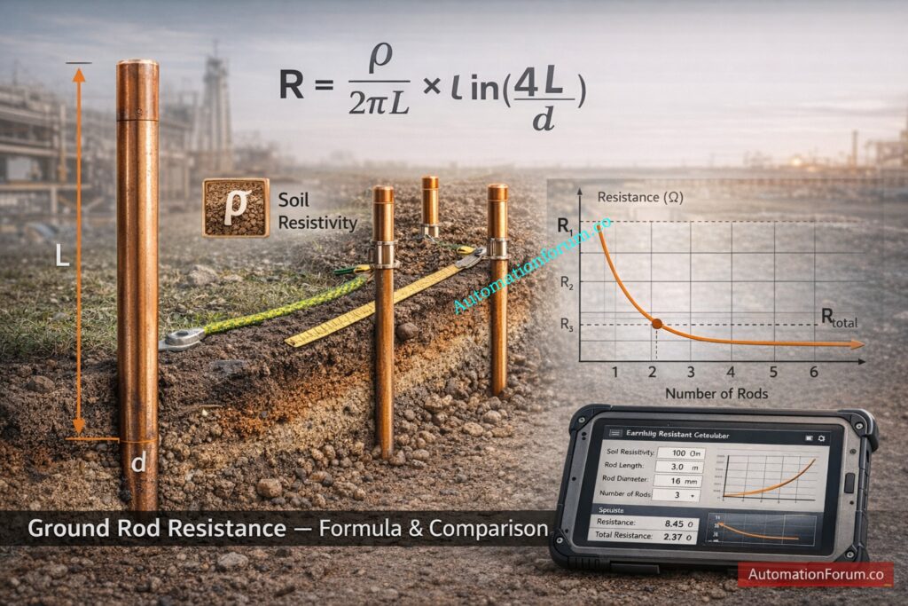
The calculator employs the standard engineering equation for figuring the earthing resistance:
R = (ρ / (2πL)) × ln (4L / d)
Where:
R = resistance of ground rod
ρ = soil resistivity
L = rod length
d = rod diameter
4–20 mA Loop Signal Verification SOP: Live Signal Verification 4 to 20 mA Loop Standard Operating Procedure (SOP)
How Multiple Ground Rods Reduce Total Grounding Resistance
To lower total resistance, many industrial setups include several rods. When rods are joined, they work together and lower the total grounding resistance.
The calculator figures out this total resistance by looking at how many rods are in the grounding system. With this earthing resistance calculator, engineers can easily test out several grounding setups and choose the best one for industrial earthing systems.
Critical Panel Door Earth Bonding Procedure Every Engineer Must Know: Panel Door Earth Bonding Procedure: Ensuring Safety and Reliability
Key Parameters Used in the Instrument Earthing Resistance Calculator
For reliable earthing design, it’s important to know what each parameter means and how it affects the field. The calculator takes a few input data, like soil resistivity (ρ), ground rod length (L), rod diameter (d), number of rods (n), and rod spacing, and turns them into an estimate of resistance. Below are the parameters explained with engineering context and industrial examples.
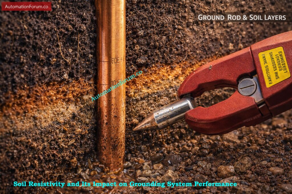
Soil Resistivity and Its Impact on Grounding System Performance
- Units: Ω·m. Soil resistivity is the single most influential variable. Clayey, moisture-rich soils have low resistivity (e.g., 20 – 200 Ω·m), whereas dry sand, gravel or rock can exceed 1,000 – 2,000 Ω·m.
- Field practice: measure using a Wenner or fall-of-potential test across representative locations (near control rooms, tank farms, and proposed electrode locations). Don’t assume textbook values for site-specific design. Soil resistivity varies with depth, season and proximity to drainage.
- Example: a coastal refinery marsh layer may show 30–80 Ω·m, whereas rocky plateau sites may show 1,000 – 2,000 Ω·m – design choices differ radically between them.
Ground Rod Length and Its Effect on Earthing Resistance
- Units: meters. Longer rods reduce resistance roughly inversely with length in the formula. Typical driven rods in process plants are 2.4 m (8 ft) or 3.0 m. Where space allows, deeper rods (or driven pipe electrodes) are preferred.
- Field note: rock or high groundwater tables may limit achievable depth. When you can get deeper than 3 m, resistance falls significantly.
Ground Rod Diameter and Mechanical Strength Considerations
- Units: meters (often entered as mm in UI). Standard driven rods are 16 mm to 25 mm in diameter (solid copper or copper clad steel). Diameter has a relatively minor effect versus length and resistivity, but thinner rods have slightly higher resistance and lower mechanical strength. Use thicker rods where mechanical durability and corrosion resistance matter.
Linear to Square Root Signal Conversion Explained: Linear to Square Root Extraction Signal Converter: 4-20mA, 3-15 Psi, 1-5 Volt Signals
Number of Ground Rods and Parallel Grounding Design Principles
- Installing multiple rods in parallel reduces total resistance, but returns diminish as spacing and soil overlap become limiting. The calculator uses the √n approximation to estimate the benefit of parallel rods as a first-order guide.
- Practical example: four rods in good soil may reduce resistance to roughly half a single rod – sufficient for many signal grounding applications; in high-resistivity sites you must either add many rods, increase depth, or install a ground grid.
Ground Rod Spacing and Avoiding Overlapping Resistance Zones
- Proper spacing avoids overlapping ‘resistance zones’ around each rod. A common field rule-of-thumb is rod spacing ≥ 3·L (three times the rod length) to reduce interaction. If rods are too close, the √n approximation becomes optimistic.
- Industrial practice: for three-meter rods, 9 m spacing is conservative; for 2.4 m rods, 7 – 8 m spacing. Where space is constrained, a ground ring or chemical treatment may be better than closely clustered rods.
Test Your PLC Analog Output Troubleshooting Skills: Troubleshooting Analog Output Signals in PLC Loops – Advanced Scenario-Based Quiz for Process Industries
Typical Grounding Parameter Values Used in Industrial Earthing Design
- Soil resistivity: 30 – 2,000 Ω·m depending on site.
- Rod length: 2.4 m (standard), 3 m (preferred).
- Diameter: 16 mm copperclad (standard), 25 mm for mechanical robustness.
- Number of rods: single for small cabinets; 2 – 6 for control rooms; many tens for substation-grade grids.
- Spacing: 3 – 5 m minimum; 3·L is a conservative design approach.
Engineers must always pair calculator outputs with field measurements and local construction constraints. The calculator gives a first-order estimate to plan materials, layout and potential remediation.
Earth Pit Explained – What Every Engineer Should Know: What is an Earth Pit?
Who Should Use the Instrument Earthing Resistance Calculator
This instrument earthing calculator is directly useful to a range of professionals in process industries:
- Instrumentation engineers designing chassis and signal reference points for PLC and DCS cabinets.
- Electrical engineers performing earthing studies for new substations, control rooms and instrument shelters.
- Maintenance teams troubleshooting intermittent 4-20 mA noise or component failures where earthing is suspect.
- Commissioning engineers validating grounding performance during plant startup and HART/Digital I/O acceptance tests.
- EPC instrumentation designers sizing foundations, rods and guardrails for control-room layouts.
- Automation specialists diagnosing network comms problems where low-impedance chassis earths reduce electromagnetic noise.
It is effective in both the design stage (to choose rod size/quantity and preliminary layout) and the maintenance/commissioning stage (to interpret soil tests and decide remediation steps). Use it as a quick engineering estimator – not a substitute for a full substation grounding analysis when high fault currents are involved.
Essential Earthing Drawings Every Engineer Must Understand: Earthing Drawing
How to Use the Instrument Earthing Resistance Calculator Step by Step
Below is a practical field procedure to use the calculator and interpret the results. The steps assume the calculator UI accepts direct numerical inputs and returns single-rod resistance, combined resistance and a guidance status.
Step 1 Identify Soil Type and Measure Soil Resistivity
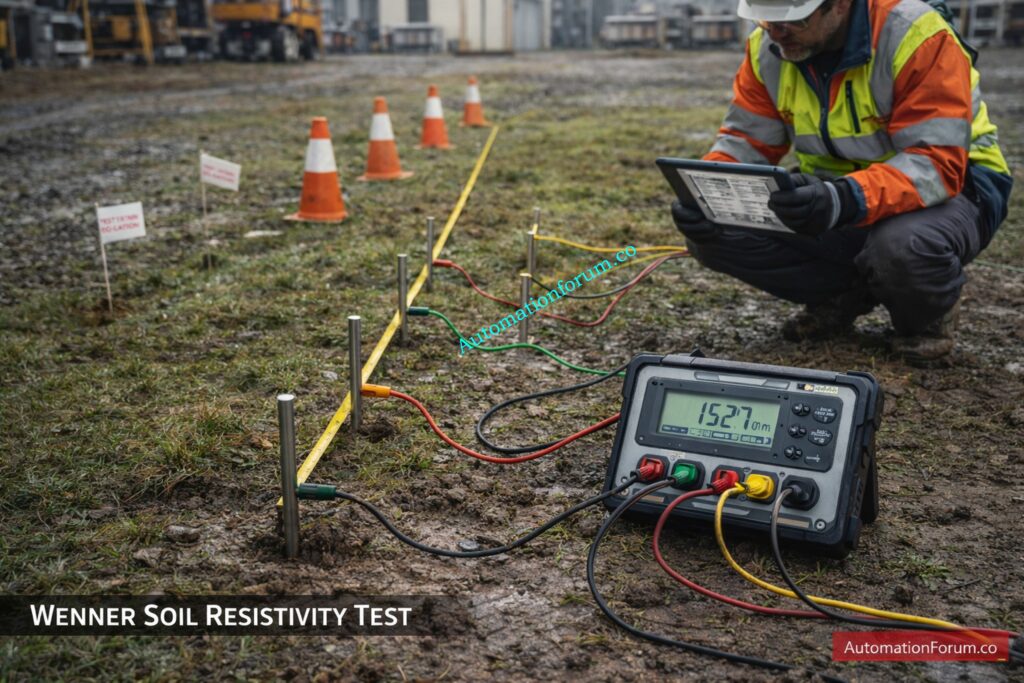
- Perform a Wenner four-pin test in-situ at the proposed electrode location and record ρ (Ω·m). If you don’t have a measurement, use conservative estimates (clay 20-100 Ω·m, moist soil 100-300 Ω·m, sandy 300-1,000 Ω·m, rocky >1,000 Ω·m). Enter the measured or chosen ρ in the calculator.
Step 2 Enter Ground Rod Length in the Calculator
- Input the driven rod length in metres. Choose the deepest practical driven depth (2.4 m is common; 3.0 m is preferred if achievable).
Step 3 Input Ground Rod Diameter
- Enter diameter in mm (the calculator will convert to metres). Standard selection: 16 mm copperclad (0.016 m).
Step 4 Specify the Number of Ground Rods Installed
- For a single cabinet choose n = 1; for a control room or field marshalling kiosk, start n = 2-4; for large substations you will design a grid.
Step 5 Enter Ground Rod Spacing Distance
- Provide spacing (m). If spacing is ≥ 3·L, the √n approximation is more valid. If spacing is closer, treat the calculator result as optimistic.
Step 6 Run the Earthing Resistance Calculation
- Click Calculate. The calculator returns:
- R (single rod) using R = (ρ / (2πL))·ln(4L/d)
- R_total using R_total ≈ R / √n
- % reduction relative to single rod.
Step 7 Interpret the Calculated Ground Resistance Result
- Compare R_total to project targets: PLC chassis < 1 Ω preferred, 4-20 mA loops < 2 Ω, general signal ground < 5 Ω. If R_total > target, decide remediation.
Earth Fault vs Ground Fault – Don’t Confuse These: Difference between Earth Fault and Ground Fault
Example Ground Rod Resistance Calculation for Industrial Earthing Design
Use typical field inputs: ρ = 150 Ω·m, L = 2.4 m, d = 16 mm = 0.016 m, n = 3.
- Compute denominator: 2πL = 2×3.141592653589793×2.4 = 15.079644737 (approx).
- Compute argument of ln: 4·L/d = 4 × 2.4 / 0.016 = 9.6/0.016 = 600.
- Compute natural log: ln(600)=6.396929655216146 (approx).
- Compute ρ/(2πL): 150/15.079644737=9.9498743719 (approx).
- Single-rod resistance R: 9.9498743719×6.3969296552=63.63143595Ω (single rod).
- For n = 3, total R_total = R/√3 = 63.63143595/1.732050808 = 36.73762668 Ω.
- Percent reduction: (1-R_total/R) × 100 = (1-36.73762668/63.63143595)× 100 ≈ 42.3%.
Interpretation: 36.7 Ω is far above instrumentation targets remedial actions (deeper rods, many more rods, chemical treatment or a ground grid) are required. This step-by-step example shows that in moderate-to-high resistivity soils, driven rods alone rarely achieve <1 to 2 Ω without additional measures.
Take a look at this example:
Soil resistivity = 150 ohm meter
Rod length = 2.4 meters
Rod diameter = 16 mm
Number of rods = 3
If you use the ground rod resistance calculation formula, you may figure out that one rod’s resistance is about 63 ohms.
The total resistance may go down to about 36 ohms when three rods are inserted.
If the goal grounding resistance is less than 5 ohms, you will need more rods or better grounding methods.
Neutral vs Earth vs Ground – Explained Clearly: Difference between Neutral, Earth and Ground
When to Use an Instrument Earthing Resistance Calculator in Process Plants
Use the earthing resistance calculator in real life, like when you need to:
- When designing a grounding system, you need to figure out how many rods and how long they should be to reach the signal-ground aim before you finish the civil work.
- During plant commissioning, we compare the expected resistances to the observed resistances. If the measured resistance is worse than the predicted resistance, it means that there are problems with the construction or the soil conditions.
- When fixing instrumentation noise, if you think that PLC communication faults or 4–20 mA jitter are caused by the earth, utilize the calculator to see if the local chassis earth needs to be reinforced.
- During earthing audits or safety inspections: to document expected resistance under different soil conditions and propose remediations.
- During expansion of control systems: when adding remote I/O racks or analyzer shelters, quickly verify whether the existing earth will support additional loads.
The tool is best used in tandem with field measurements (Wenner tests or fall-of-potential data) and engineering judgment around fault current expectations and bonding practices.
Earth Fault Explained – Causes Engineers Must Know: What is an Earth Fault?
Where Instrument Earthing Calculators are Used in Industrial Facilities
Typical plant locations where this calculator and the design it informs are important:
- Control rooms – central DCS/PLC rooms where chassis earths must be low-impedance for stable communications.
- PLC cabinets & marshalling panels – local earth stakes reduce loop noise for analog cards.
- DCS racks and remote I/O stations – distributed earthing strategy for large plants.
- Instrument field panels and junction boxes – local grounding electrodes can cut common-mode noise on long cable runs.
- Analyzer shelters and lab enclosures sensitive equipment works better with specialized low-resistance earths.
- Substations and transformer yards grid design for fault dissipation (the calculator is just a basic approximation; large substations need a thorough IEEE/IEC analysis).
- Tank farms and loading gantries earthing and equipotential bonding keep static and lightning from damaging them.
- Offshore platforms have specific problems (such shallow water and corrosion) that need better cathodic protection and bonding.
In these situations, solid instrument grounding makes the system more stable, cuts down on false trips, and keeps people and equipment safe.
How to Check Proper Earthing in Your Home: How to check if the earthing is properly done in our home?
Practical Engineering Tips to Achieve Low Ground Resistance in Industrial Plants

Field-tested methods for meeting the earthing goals utilized in industrial earthing design:
- Increase the depth of the rods. Go deeper where the ground conditions allow it. Deeper rods reach areas with less moisture.
- Use several rods with the right amount of space between them. Keep the space between them at least 3·L to reduce interaction and get the √n advantage.
- Use ground enhancement compounds (GECs) like bentonite, conductive cement, or designed backfill to make the area around the rods much less resistant. Use things that are rated for long-term stability and are safe to use in your environment.
- Set up ground grids or mats. To get sub-ohm resistances, put rods and a copper-bonded grid together in the control room area.
- Use electrodes that are bonded with copper or made of solid copper. This will make them less likely to corrode and have less contact resistance.
- Bonding conductors and a single-point connection: use low-impedance copper conductors to link cabinets to the electrode. Don’t use numerous floating grounds to avoid loops.
- Check and measure regularly. Retest earth resistance every season and after any major changes. Moisture and corrosion modify resistance over time.
- Keep track of construction specifics, such as soil resistivity tests, rod kinds, and spacing as-built, so that future engineers can understand how well the work was done.
When field data show higher-than-expected resistance, these practical steps are common sense for maintenance crews and designers.
Earth Resistivity Explained for Engineers: What is earth resistivity?
Earthing and Its Types — Complete Engineer Guide: What is earthing? and its types
Importance of Proper Instrument Grounding in Process Industries
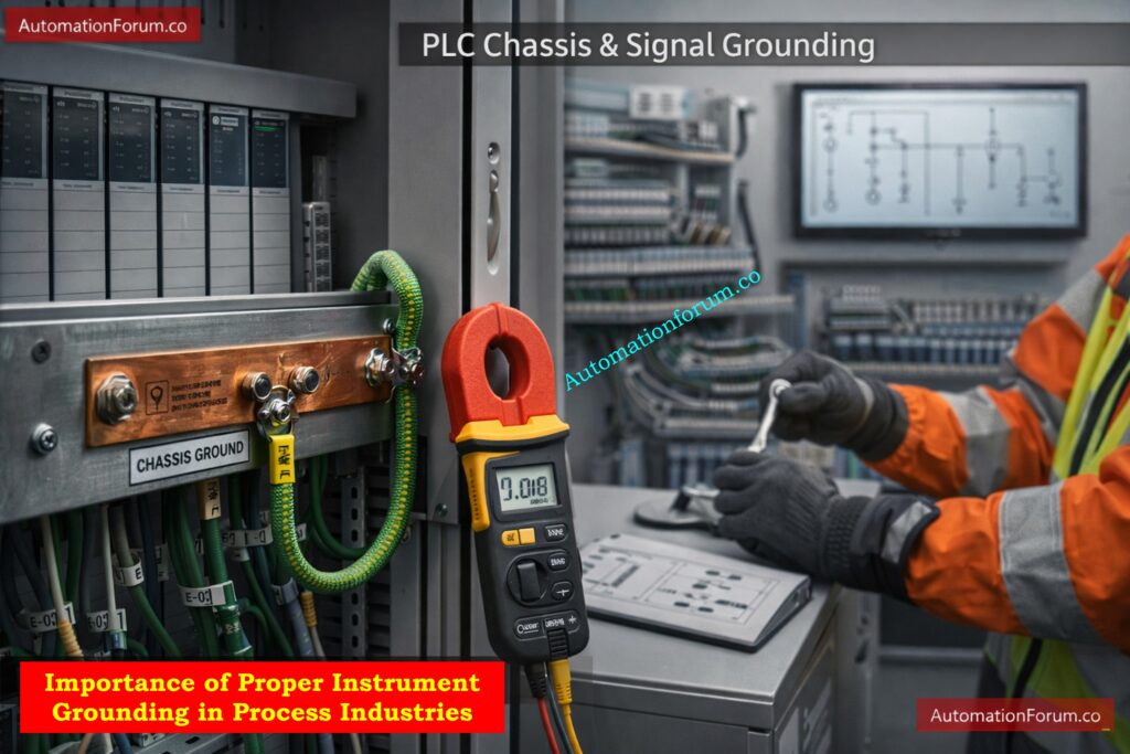
- Proper instrument grounding is essential for reliable operation of modern industrial automation systems. A well designed grounding system minimizes electrical noise, stabilizes instrumentation signals, and protects equipment from surges and lightning.
- The instrument earthing calculator provides engineers with a practical method to estimate grounding resistance during system design and troubleshooting. By performing quick earthing resistance calculations based on soil properties and electrode parameters, engineers can evaluate grounding performance before installation.
- Engineers can use this tool to assist them construct reliable PLC grounding systems and keep their instruments working correctly.
- In the end, correct grounding makes plants more reliable, increases signal accuracy, and helps process industries run more safely.
Detect Signal Noise Before It Causes Failures: Noise and Signal Stability Observation for Running Inspection in Instrumentation and Control Systems
FAQs for Instrument Earthing Resistance Calculator
How do you calculate earthing resistance?
To find the earthing resistance, use the formula R = (ρ / 2πL) × ln(4L / d), where ρ is soil resistivity, L is rod length, and d is rod diameter.
Engineers also use the fall of potential test and other methods to measure it in the field.
What is the resistance of instrument earthing?
For instrumentation systems, the recommended earthing resistance is less than 1 ohm for PLC and control systems.
General instrument grounding in industrial plants should typically be below 5 ohms.
Is 20 ohms of resistance in a ground bad?
Yes, 20 ohms is considered high for industrial instrumentation grounding.
Most process plants aim for 1 to 5 ohms to ensure stable signals and proper surge protection.
Which instrument is used to measure earthing resistance?
Earthing resistance is measured using an Earth Resistance Tester (Earth Tester).
It measures ground resistance using techniques such as the three point or fall of potential method.
Proper Instrument Grounding to Eliminate Noise: How to properly ground an Instrumentation System to reduce noise?
How to check instrument earthing?
Instrument earthing is checked by measuring the ground resistance using an earth tester or clamp on ground tester.
The measured value is then compared with the acceptable grounding resistance limits.
Stop EMI Noise in Industrial Systems: How to reduce electromagnetic interference noise?
Which instrument is used for measuring resistance?
A digital multimeter or an ohmmeter is the most popular way to measure electrical resistance.
You can also utilize equipment like the Wheatstone bridge or micro ohmmeters to get very accurate measurements.
What is the typical spacing between ground rods?
To keep resistance zones from overlapping, ground rods should be spaced at least three times the length of the rod.
For instance, there should be roughly 9 meters between rods for a 3-meter rod.
What is the typical spacing between ground rods?
To keep resistance zones from overlapping, ground rods should be spaced at least three times the length of the rod.
For instance, there should be roughly 9 meters between rods for a 3-meter rod.
Eliminate Measurement Noise in Instrumentation: How to reduce measurement noise?
What is the ideal earthing resistance for instrumentation systems?
The 3L rule says that grounding rods should be spaced around three times the length of the rod.
Correct spacing makes sure that each rod works well to minimize the total grounding resistance.
Refer the below link for the Test Your PLC Digital Output Troubleshooting Skills: